KADIR HAS UNIVERSITY
GRADUATE SCHOOL OF SCIENCE AND ENGINEERING
ANALYSIS OF VISIBLE LIGHT COMMUNICATION SYSTEMS AND ADAPTIVE EQUALIZATION EFFECTS
MASTERTHESIS
ATİLLA MAMUŞ
Atil la Ma muş M.S . The sis 2015 S tudent’ s F ull Na me P h.D. (or M.S . or M.A .) The sis 20 11
ANALYSIS OF VISIBLE LIGHT COMMUNICATION SYSTEMS AND ADAPTIVE EQUALIZATION EFFECTS
ATİLLA MAMUŞ
Submitted to the Graduate School of Science and Engineering in partial fulfillment of the requirements for the degree of
Masterof Science in
ELECTRONICS ENGINEERING
KADIR HAS UNIVERSITY November, 2015
i
“I, Atilla Mamuş, confirm that the work presented in this thesis is my own. Where information has been derived from other sources, I confirm that this has been indicated in the thesis.”
_______________________ ATİLLA MAMUŞ
ii
ABSTRACT
ANALYSIS OF VISIBLE LIGHT COMMUNICATION SYSTEMS AND ADAPTIVE EQUALIZATION EFFECTS
Atilla Mamuş
Master of Science in Electronics Engineering Advisor: Prof. Dr. Erdal Panayırcı
November,2015
Communication by means of visible light is a newly developing technology that has been brought up as an alternative to the current electromagnetic based communication systems. The recently conducted studies led to the use of LED Technology for illumination purposes and for this technology to have an edge over devices that consume excessive energy as presently being used by us. LED technology is predicted to become an important part of illumination systems especially in consideration of the low energy consumption, low voltage use, product longevity and small size the technology can provide. Furthermore, the use of semi-conductor materials in the LED technology lends this illumination tool the capability to be turned on and off very fast in comparison to the other similar purpose devices. This capability makes it possible for LED technology to be used as a means of data transmission in addition to being a means of illumination. Studies are being conducted to use LEDs effectively as an optic transmission transmitter antenna and application of modulation techniques used in electromagnetic systems to VLC technology for purposes of achieving resistance against white noise, reflections, refractions and echoes. In literature, the model of receiving data by means of adaptive filters and its processing has been used in very limited number of studies and in these studies, generally LMS algorithms were used. In this dissertation, an empty room in rectangular prism shape in pre-determined dimensions was used with LED panels, in numbers and positions previously determined, which sent data, whereby, the impulse response displayed by the channel until the data sent that reached the photo detector was analyzed according to different FOV angles in AP PE ND IX C APPENDIX B
iii
computer environment and later on, the data was sent to the receiver through these channels that have differing impulse response based on specific FOV degrees. The data that is processed at the receiver was passed through adaptive filters to evaluate byte error rate performances in the computer environment. LMS and RLS algorithms were used in the adaptive filter. The simulation results have been displayed in graphics of bit error rate change based on SNR, and it has been observed that the adaptive filter on which RLS algorithm is used provided better results than the adaptive filter on which LMS algorithm was used.
iv
ÖZET
GÖRÜNÜR IŞIKLA İLETİŞİM SİSTEMİNİN VE ADAPTİF KANAL DENKLEŞTİRİCİ ETKİSİNİN ANALİZİ
Atilla Mamuş
Elektronik Mühendisliği, Yüksek Lisans Danışman: Prof. Dr. Erdal Panayırcı
Kasım, 2015
Görünür ışıkla iletişim yeni gelişmekte olan bir teknoloji olup bugünkü elektromanyetik kökenli iletişim sistemlerine karşı alternatif bir sistem olarak gösterilmektedir. Yakın zamana kadar yapılan çalışmalar LED teknolojisinin aydınlatma aracı olarak kullanılmasına ve günümüzde kullanılan aşırı enerji tüketen cihazlara karşı üstünlük sağlamasına sebep olmuştur. Düşük güç tüketimi, düşük voltaj kullanımı, uzun ömürlü olması, ve küçük boyutlu olmaları sebebiyle LED’ler geleceğin aydınlatma sistemlerinin en önemli parçalarından biri olacağı öngörülmektedir. Ayrıca LED teknolojisinin temelinde yarı iletken materyallerin kullanılması bu aydınlatma aracına, diğer aydınlatma araçlarına uygulanamayacak derecede çok hızlı açılıp kapanma özelliğini de vermektedir. İşte bu özellik LED teknolojisini bir aydınlatma aracı olarak kullanılmasının dışında bir veri iletim aracı olarak kullanılmasına da imkan sağlamaktadır. LED’lerin bir optik iletim verici anteni olarak etkin biçimde kullanılması, beyaz gürültüye, yansımalara, kırılmalara ve ekolara karşı dayanıklılık sağlaması amacıyla, elektromanyetik sistemlerde kullanılan modülasyon teknikleri VLC teknolojisine uygulanmasıyla ilgili çalışmalar mevcuttur. Literatürde uyumlu süzgeçlerle verinin alınıp işlenmesi modeli çok sınırlı sayıda çalışmalarda kullanılmış olup, bu çalışmalarda da genellikle LMS algoritmaları kullanılmıştır. Bu tezde, boyutları belirtilmiş dikdörtgen prizma şeklindeki içi boş bir odanın yine sayıları ve konumları belirli, LED’lerden oluşan aydınlatma panellerinden gönderilen verinin foto detektöre ulaştığı ana kadar, kanalın sinyale karşı gösterdiği dürtü tepkisi bilgisayar ortamında farklı FOV açılarına göre analizleri yapılmış, daha AP PE ND IX C APPENDIX B
v
sonra bu belirli FOV derecelerine göre değişen dürtü tepkisine sahip kanallardan veriler alıcıya gönderilmiş, alıcıda işlenen veri, uyumlu süzgeçlerden geçirilerek, bit hata oranı başarımları bilgisayar ortamında değerlendirilmiştir. Uyumlu süzgeçte LMS ve RLS algoritmaları kullanılmıştır. Simülasyon sonuçları SNR’a bağlı bit hata oranı değişiminin grafikleri şeklinde oluşturulmuş olup, RLS algoritması kullanılan uyumlu süzgecin LMS algoritması kullanılan uyumlu süzgeçten daha iyi sonuçlar verdiği gösterilmiştir.
Anahtar Kelimeler: Görünür Işıkla İletişim, Denkleştirici, LMS, RLS APPENDIX B
vi
Acknowledgements
I would like to thank my thesis advisor Prof. Dr. Erdal Panayırcı for his kind support, assistance, and patience during my thesis. Without his guidance, it would be impossible for me to finish this thesis.
This master thesis is supported by COST-TÜBİTAK under the project number 113E307. AP PE ND IX C AP PE ND IX C
vii
Table of Contents
Abstract Özet Acknowledgements List of Tables ix List of Figures xList of Abbreviations xiv
1 Introduction 1
1.1 Visible Light Communication ………...….. 4
1.2 Requirement for VLC Systems …...……….... 8
1.3 Visible Light Communication Application Examples .………... 9
1.4 The History of Visible Light Communication ………... 12
1.5 Literature Review ……….... 13
1.6 Contribution and Organization of Thesis ……….... 18
2 Background Theory 20
2.1 Light Emitting Diode ……..……….... 20
2.1.1 Phosphor based White LEDs ..………... 22
2.1.2 Ultraviolet based White LEDs ………... 23
2.1.3 RGB LEDs ………..….……….. 23
2.2 White LEDs as a Powering and Lightening Element ………... 23
2.3 Photodiode ...………….………...………...………...………... 26
2.4 Propagation of Light ...………...………...………...………... 28
2.5 Channel Model …...…...………...………...………...………... 33
2.5.1 Mean Delay and RMS Delay Spread……….. 34
2.5.2 Channel Noise ……….... 35
2.6 Filters Used in VLC Systems ………..……...………... 36 AP
PE ND IX C
viii
2.6.1 Raised Cosine Filter ……….……….. 37
2.6.2 Adaptive Channel Equalization ….……….... 41
3 Implementation Of Simulation Medium 46
3.1 Simulation Medium…...……….. 46
3.2 Calculation of Illumination ………...……….. 48
3.3 Calculation of Received Power ……….……….. 51
3.4 Calculation of Impulse Response …..……….. 53
3.5 Mean Delay and RMS Delay Spread of Simulated Room …….. 55
3.6 Theorical SNR and Theorical Bit Error Rate ……….. 57
3.7 Implementation of Raised Cosine Filter ………...…….. 59
4 Tests and Results 61
4.1 Steps of Tests ……….. 61
4.2 Effect of FOV ………...……….. 64
4.3 Effect of Symbol Duration …...……….……….. 65
4.4 Effect of Noise ………..……….. 67
4.5 Effect of LMS and RLS parameters ………..…….. 67
4.6 Effect of Train Sequence Length …………..……….. 68
4.7 Results of BER versus SNR, under Different Symbol Periods and FOV ………. 69
4.8 Comparison of Time Complexity of LMS and RLS ……….…………..……….. 71
4.9 Conclusion ...………..………...……….. 72
4.10 Future Work .………..………...……….. 73
References 74
ix
List of Tables
Table 3.1 Simulation Parameters ... 48 Table 4.1 The time consumption of RLS and LMS under different signal
lengths (seceond) ... 71 AP PE ND IX C APPENDIX B
x
List of Figures
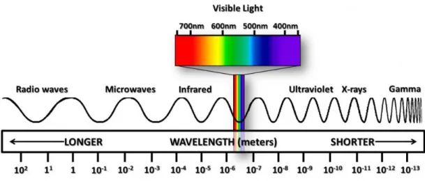
Figure 1.1 Place of the visible light in the electromagnetic spectrum ... ..4
Figure 1.2 Block Diagram of Intensity Modulated Direct Detection Channel ... 6
Figure 1.3 VLC Example in Office Environment ... 6
Figure 1.4 Global Mobile Traffic Prediction ... 8
Figure 1.5 Development Coefficient in Spectral Efficiency ... 8
Figure 2.1 LEDs and working principle ... 21
Figure 2.2 Normalized optical spectrum of a white LED... 22
Figure 2.3 Basic biasing arrangement and construction and Circuit symbol representation of photodiode ... 26
Figure 2.4 Received Power on Photodiode ... 28
Figure 2.5 Spectral Reflectance values of different materials according to the light wavelength ... 29
xi
Figure 2.6 Light rays emitted from a single source, falling on one point on
each one of the two surfaces at a right angle to each other ... 30
Figure 2.7 1st order reflection ... 31
Figure 2.8 Demonstration of the optical power produced by 1st order reflection ... 32
Figure 2.9 Visible Light Communication Channel Model ... 33
Figure 2.10 a) Signal sent in time domain by means of OOK Modulation; b) frequency components of the signal sent; c)signal received in time domain; d) frequency components of the signal received ... 37
Figure 2.11 Requency response and impulse response of raised cosine filter ... 40
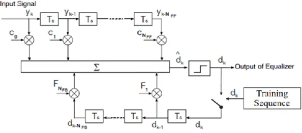
Figure 2.12 Block diagram of Decision Feedback Equalizer ... 42
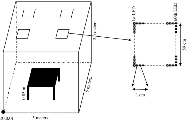
Figure 3.1 Simulation Medium ... 47
Figure 3.2 Rays that originate from multiple sources and directly reach the surface ... 49
Figure 3.3 Direct Illumination on desk ... 50
Figure 3.4 Direct and 1st order reflection’s iIllumination on desk ... 51
xii
Figure 3.6 Received Power with direct and 1st order illumination ... 52
Figure 3.7 Impulse response at (0.1 0.1 0.85) for 60 deg FOV a) with 1st reflection b)only direct illumination c) with 1st reflection in time range [6 22] c) only direct illumination in time range [6 22]... 54
Figure 3.8 a) Transmitted Signal Level X(t) b)Received signal Level Y(t) at N(t)=0 ... 55
Figure 3.9 Mean Delay time at any location at desk ... 56
Figure 3.10 RMS Delay Spread at any location at desk ... 56
Figure 3.11 Theorical SNR under direct illumination ... 58
Figure 3.12 Theorical SNR under direct and 1st order reflection illumination ... 58
Figure 3.13 Theorical BER ... 59
Figure 3.14 Frequency response of Raised Cosine Filter ... 60
Figure 3.15 a) Received Signal before Raised Cosine Filter b) Received Signal after Raised Cosine Filter... 60
Figure 4.1 System Block Diagram ... 62
Figure 4.2 Obtained symbol by wıthout equalization ... 63
xiii
Figure 4.4 Effect of FOV ... 64
Figure 4.5 Effect of Symbol Duration ... 65
Figure 4.6 Effect of SNR ... 66
Figure 4.7 Eefect of control parameter on LMS algorithm ... 68
Figure 4.8 Effect of control parameter on RLS algorithm ... 68
Figure 4.9 Effect of Train Sequence Length ... 69
Figure 4.10 Results of BER versus SNR, under Different Symbol Periods and FOV ... 70
xiv
List of Abbreviations
AC Alternating Current
ANN Artificial Neural Network
BER Bit Error Rate
CIR Channel Impulse Response DFE Decision Feedback Equalizer
FBF Feed-Back Filter
FEC Forward Error Correction FFF Feed-Forward Filter
FOV Field of View
IM/DD Intensity Modulated Direct Detection ISI Inter Symbol Interference
LED Light Emitting Diode
LMS Least Mean Square
LOS Line Of Sight
LTE Linear Transversal Equalizer
OOK On Off Keying
OWC Optical Wireless Communications PWM Pulse Width Modulation
RF Radio Frequency
RGB Red, Green, Blue
RMS Root Mean Square
RLS Recursive Least Square SNR Signal Noise Ratio
VLC Visible Light Communication AP PE ND IX C APPENDIX B
1
CHAPTER 1 INTRODUCTION
Before the discussion moves to the communication by visible light, it is important that we understand currently used communication technologies. Before all else, a definition of communication can be made as the transmission of information from one place to another. The communication method could be via cable or wireless. Communication technologies could employ typical copper cables, CAT5, CAT6 category cables and most popularly fiber-optic cables as the medium. On the other hand wireless communication technologies use air instead of cables as the
information transmission medium. Your mobile phone, laptop computer, wireless keyboard/mouse set, wireless earphones and similar devices all transmit information by identification of changes in the electrical field (or in connection with this the electromagnetic field) on the other side (receiver).
Optical Wireless Communications (OWC) is a newly developing technology that provides the media for wireless communication by using infrared, visible or ultraviolet frequencies. Visible Light Communication (VLC) systems on the other hand is a technology that provides wireless communication by using Light Emitting Diode (LED) in visible light frequency with great economic potential. In other words, VLC is the name for a new communication technology that would support the communication currently taking place at radio frequency (RF) band. Visible Light Communication technology is based on transmitting information between two or
2
more points by using light in the light band visible to the eye. That is to say, it is possible to carry out activities such as going on the internet, holding voice or video calls, watching videos by means of visible light communication technology. VLC, which operates on optic bands and does not require a license for use and has high bandwidth but low costs, has shown itself to be a complementary element in some applications while being a strong alternative in others existing wireless
communication technologies.
In traditional radio communication, due to the excessive increases experienced in the fill factor of the frequency spectrum, recently significant difficulties have been encountered in electrical wireless communication technologies. An alternative solution to this is the visible light communication. The subject of communication in visible light band that has a wide and unregulated frequency spectrum has been intensely researched and become the focus of development studies in recent years. Some studies regarding infrared light and laser systems that are the premises of visible light communication and wireless optic communication are currently still in progress. However, generally due to restrictions such as the procurement and cost or the necessary materials, the eligibility of the environment and similar, widespread use has not been possible by the final users. The wireless optic communication handled by using the wavelengths on the visible band of electromagnetic spectrum is a solution to these problems. The ease of procuring the receiver and transmitter resources that are used in Visible Light Communication, which is a type of optic communication whereby the wavelengths in visible band are used, and their lower costs as well as their use for illumination and reaching high data speeds with the communication techniques used make widespread use of VLC systems for wireless optic communication.
3
The specifications of the LEDs used for VLC technology renders the systems using this technology popular. The longevity and low energy consumption of LEDs provides advantages in comparison to the other light sources. The simultaneous realization of illumination and communication functions results in VLC Systems to have a wide field of use. The LEDs that are used in the illumination of the interiors of offices can also be used in intra-office wireless communication. It is known that the Visible Light Communication besides being used among the vehicles in traffic can also be used for communication inside trains and airplanes [1].
Within the scope of this dissertation, the VLC systems have been discussed, which provide the means for wireless communication by using LED in visible light
frequency, which has great economic potential where OWC is concerned. Thanks to its superior properties and wide field of use VLC has the potential to achieve a breakthrough in the area of wireless communication and the developments in this field have been predicted to lead to great changes in the wireless market that is presently dominated by RF technologies. The long-term vision of our country to become the center of production in Eurasia in medium and high technology products could prove to be very profitable for the economy as the R&D activities that would set the stage for commercialization in the field of VLC are performed, VLC
technologies oriented to differing wireless applications are developed, and VLC system products by using these are realized [2]. Although there are presently systems working on VLC in the world, these are not able reach the speed of RF systems. With VLC, fast communication can only be possible in enclosed environments. To achieve this improvement some signal processing techniques that increase the data speed are being implemented. One of these methods is to use Adaptive Equalization.
4
These are methods that are well known in Least Mean Square (LMS) and Recursive Least Square (RLS) literature to ensure filter adaptation [3]. By using these methods the communication speed of VLC could be brought up to GBit/s levels. In our country research studies on the subject are being carried out by limited number of universities and companies. By means of this dissertation it has been aimed to accumulate knowledge in the field of communication with visible light, modeling of channels for VLC Systems that can be used in different environments and increasing the speed of the channel that has been modeled, by using different adaptive
equalizers.
1.1 Visible Light Communication
Light radio signals exist in electromagnetic spectrum that contains signals such as the x-rays. The light is the only type of luminescence that is visible among
electromagnetic rays.
5
The wavelength of visible light is in a range of 375 nm – 780 nm. Visible Light Communication is conducted by LEDs that are used for illumination at wavelengths between 375 nm and 780 nm. When we look at the system in terms of the wave width, we see that the communication bandwidth is approximately 400 THz wide. The place of Visible Light Wavelengths in electromagnetic spectrum is shown in Figure 1.1.
When we separate visible spectrum in terms of colors, a separation for colors in following ranges could be observed; Purple color 380 - 450 nm, Blue color 450 - 495 nm, Green color 495 - 570 nm, Yellow color 570 - 590 nm, Orange color 590 - 620 nm, and Red color 620 - 750 nm. By using this information it is possible to use a transmission band range in relation to the color of the light the LED radiates. LEDs differ according to the use of the colors in the visible spectrum. There is a
diversification in the form of; RGB (red, green, blue), and phosphor based white LEDs. Besides LEDs, Photo detectors are also important due to the fact that they are used as receiving sources.
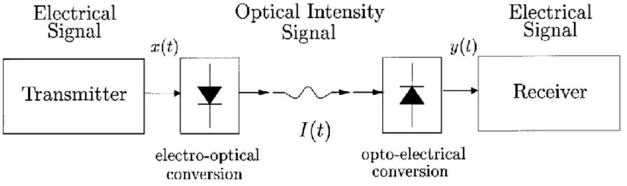
VLC, in a similar manner to the other wireless optic communication technologies, takes Intensity Modulated Direct Detection (IM/DD) channels as the basis. When we mention IM/DD it is about the circuits whereby electrical-optical transformations take place as shown in Figure 1.2. Instantaneous optical density i(t), is modulated in direct proportion to the input signal, x(t). This density modulation is performed by the LED lamps in visible light communication. After the modulation, data is
transmitted via density signal channel. The photo diode that is available as the photo detector in receiver, transforms the received optic intense signal into electrical current y(t) after detecting it.
6
Fig 1.2 Block Diagram of Intensity Modulated Direct Detection Channel
The light that is emitted from the LEDs that are used for both illumination and communication, reaches the photo detectors either directly or by reflection. When we consider how the light is dispersed at a certain angle we can understand that many signals reach the receiver either directly or by being reflected. The signals sent through dissemination of light can be received by means of connecting the photo detectors to the laptops in an office with internet connection.
Fig 1.3 VLC Example in Office Environment [4]
Furthermore output requirement could also be met by a direct command to the printer. In the example showing the use of VLC systems in an office environment in
7
Figure 1.3, the communication provided is one way. For a duplex communication, all sources to be involved in data transmission must be in possession of LED sources. For VLC, the light collected as a result of reflections is also important in addition to the directly transmitted light. The reason for this is the fact that the reflected signals lead to Inter Symbol Interference (ISI). For this reason the delay spread of the channel is required to be known for its characteristics to be determined.
Visible light communication has advantages and disadvantages like RF and IR communications. VLC communication is more advantageous in terms of service and bandwidth in comparison to IR and RF communications. However, in terms of coverage and mobile use, VLC has some disadvantages where RF communication is concerned. It is possible to render the indoor use of VLC, where suitable illumination is available, more attractive by some improvements. Considered from this
perspective, there are many areas of use. The fast paced development of VLC has been in progress and as such it has started to take place of RF technology in indoor environments. The fact that, with this technology, the energy consumption is low and sources could be easily obtained is quite advantageous [5]. Another superior quality of VLC systems reveals itself in health and security field. Due to the use of light as an alternative to radio waves in VLC systems, their effect on the health of humans is negligible. Radio waves have the potential of affecting the operation of, in particular, the medical devices by interference. In communication by visible light such
interference does not exist. Radio waves are emitted out from the walls without special protection/insulation. In environments requiring security, this causes a security gap. However, it is not possible for the light cross through a wall and therefore, VLC provides superior security in comparison to radio waves.
8
1.2 Requirement for VLC Systems
With each passing day the need for data increases exponentially. On the other hand the new technologies try to meet this ever increasing need. To give an example, the latest 4G system implements the repeated use of available frequencies as the mobile demand increases and capacity problems are encountered in the system. In spite of the use of serious algorithms, according to Cisco predictions, global mobile
information traffic will be reaching 24.3 Exabyte level in 2019 as shown in Figure 1.4.
Fig 1.4 Global Mobile Traffic Prediction,[6]
9
When we examine the development graphic of mobile communication technologies shown in Figure 1.5 at this point, we can see that the spectral efficiency development coefficient has been getting smaller since around 2012 and lately it has been
observed to approach the theoretical limits. Right at this point in time, the existence of a communication environment that would not act on the radio communication dealing with the ever-increasing mobile demand and decreasing technological efficiency would solve the problem. The most likely candidate for this solution seems to be the VLC technology.
1.3 Visible Light Communication Application Examples
VLC technology has not been developed to fully take place in the existing wireless communication technologies. Its purpose is to be a complementary technology where the available wireless technologies are not sufficient. VLC technology provides a wide field of research and applications. Some of the important applications are as follows:
Smart Home Network
Smart Home Network consists of systems such as sound, data and information communication systems, security-camera systems, air conditioning systems whereby the temperature could be adjusted and similar, integrated on the same centrally managed platform. VLC system provides indoor wireless communication capability including illumination, control and media stream, and internet accessibility that are necessary for the Smart Home Network. This technology reduces the cabling costs and energy consumption in buildings.
10
Mobile Connectivity
Visible light that is emitted into the environment by LED is redirected to the receiver to achieve secure data transmission. By using this technology it is possible to
transmit data at much higher speeds than is possible with wireless communication technologies such as Bluetooth or Wi-Fi.
Risky Environments
In areas where there is the risk of explosion (mines, petro-chemical facilities, oil wells, nuclear facilities, etc.) the communication can be cut off and there could be a problem arising from communication. VLC technology provides safe illumination and wireless communication in risky environments.
Vehicles and Traffic
Current LED lamps are being used on the headlights and internal illumination of the vehicles and traffic lights and streetlights as well. Under the circumstances, it is possible to use Visible Light Communication Technology in establishing
communication between the vehicles that get close to each other and the traffic lights to obtain information on the status of the roads and traffic safety applications.
Security
The fact that VLC systems can transmit data securely at high speeds is an important factor to be considered for many applications. The use of visible light provides a great advantage where the security is concerned as the light cannot go beyond the walls surrounding it.
11
Use of VLC technology in hospitals and health care premises has great advantages. The use of wireless communication systems such as the mobile phones and Wi-Fi, in hospitals especially close to the magnetic resonance imaging (MRI) devices, in the operating rooms and in some other sensitive areas of the hospital must be avoided. Due to the fact that VLC Technology is light based, it does not have a negative effect on the devices in its peripheral area.
Expansion of Wi-Fi Spectrum
When an established Wi-Fi communication system cannot meet the wireless data requirements, the VLC systems can offer additional bandwidth to be used in the medium concerned. This technology removes RF components and antenna requirement at a low cost.
Aviation
The LED lights providing illumination in planes can at the same time provide media services to the passengers as well as intra-plane communication. As such it could be possible to get rid of the network of cables surrounding the planes. This would reduce of costs of manufacturing planes as well as reducing their weight, which is an important consideration where planes are concerned.
Underwater Communication
Although radio waves cannot be transmitted underwater, visible light could provide high speed data transmission for short distances under the water. By using this property of visible light, the wireless communication between divers and underwater vehicles may be achieved.
12
In VLC technology, led lights can be used to achieve wireless sound transmission. Furthermore, numerically different sounds can be transmitted by using different color LED lights.
1.4 The History of Visible Light Communication
In fact, visible light communication using in the human life dates back in ancient time. In this time of history, people carried information for over long distances through the smoke burn fire. Another example can be given lighthouses in terms of providing guidance to the sailors in the later term of history. Most famous of
lighthouse was built by Ptolemaic Kingdom in egypt BC 280 and also it is also called The Pharos Lighthouse of Alexandria. Another earliest use of light for
communication purposes is attributted to Ancient Greeks and Romans who used their polished shields to send signals by reflecting sunlight during battles [8]. This kind of examples can be given more in the firsth term of visible light communication history. When we come to recent history of the using of light in communication sytems we encounter with the invention of Aleandre Graham Bell’s new communication machine it is called Photophone or the alternate name Radiophone. It is very prominent and outstanding invention. The principle of this machine is like that, actually there is no diffrence principally between normal classical telephone and radiophone, photophone was similar to a contemporary telephone but except that it used modulated light as means of wireless transmission while the telephone relied on modulated electricity carried over a conductive wire circuit [9]. In the system it is used that the simplest form of apparatus for producing the effect of a plane mirror of flexible material the back of which speaker’s voice is directed. Under the physical
13
effect of the voice in the air pressure, the plain mirror becomes alternately convex and concave and so and alternately scatters and condenses the light. This was the transmitter part of the system. At the receiver part is used lampblack material but after selenium cell at he focus of a parabolic mirror which is directed to the receiver and this situation is caled in communication Line Of Sight (LOS) position. The cell’s electrical resistance varied between 100 ohm to 300 ohm inversely with the falling upon it, its resistance was higher when dimly lit, lower when brightly lit. Finally signal is transformed to electrical energy from optical energy and is send to speaker, and so is obtained the sound again. These examples and explanations are given above to give information for indicate how visible light communication technology evolved in the human history.
More recent work for using LEDs to transmit data by visible light began in 2003 at Nakagawa Laboratory, in Japan. Since then, at Oxford University, there have been numerous research activities focussed on VLC, notably by Smart Lighting
Engineering Centre. Today, the VLC standardization named as 802.15 by IEEE Wireless Personal Area Networks working group.
1.5 Literature Review
White LEDs used indoor visible light communication system is proposed in [10]. In this research, the LEDs are used both illuminating and optical wireless
communication receiver. On-off Keying Return-to-Zero (OOK-RZ) coding is used for modulating. Optical lighting and optical transmission have been tested to evaluate the requirements for indoor applications. They presented that the effects of the delay problems faced in the high data rate transmission [10]. LEDs are also being used in
14
traffic for communication. In [11], road-to vehicle communication in the traffic signal lights by using the LEDs was proposed. In this research, they used a camera on the front end of the car. The camera is used for receiving information from traffic signal lights. The advantage of proposed system is multiple data can be transmitted by the LEDs and received by high-speed cameras [11]. Using the existing power-line for optical communication in a household is proposed in [12]. The power-line is used for communication between white LEDs and other networks. The also used power-lines and outlets behave as data networks and ports. The transmitted signals are added to the cyclic waveform of the alternating current (AC) for optical intensity modulation. The transmitter signal from the PC is picked through the power-line, and biased before sending to the optical receivers. So LEDs are converted the electrical signal into an optical signal. After that signals sends it to the photodiode, where it converts the captured optical signal to an electrical signal. The signal is demodulated according to the received level of light and then is sent to the mobile terminal [12]. Optical communications for outdoor communication has been discussed in [13]. Laptops and mobile phones can be used for transmitting and receiving information, using transceivers. Both LEDs and photodiodes are used as transceiver systems. To reach the most viable modulation, intensity modulation was implemented [13]. The example of VLC system in wireless underwater communication was proposed in [14]. They used VLC for robotic inspection of nuclear power plants. They also explained the solution for maintaining the consistent line of sight to maintain a communication link in detail in [14]. In this research, an optical wireless network was used between the remotely operated vehicles and control station using LEDs and photodiodes on both sides. Underwater remotely operated vehicles was used to communicate with the control station over water to transmit control signals. Both the
15
control station and vehicle are able to directing a light beam in the three-dimensional space [14]. In [15], researchers designed a prototype to demonstrate VLC using RGB LEDs and sensors. The RGB LEDs enable parallel signal communication. They also used microcontroller to control them. To switch RGB LEDs at high speeds, they used Pulse Width Modulation (PWM). To realize multiple value signals communication, the characteristics of the variation in color and change in intensity of LEDs was analyzed [15]. In [16], researchers proposed a VLC system to transmit high quality video and audio signal. The video signal was modulated by using a high speed comparator in the transmitter. The analog signal was converted from analog to digital. Signals were transmitted using the illumination LEDs in the transmitter. They also used photodiode as the receiver for sensesing the optical signals and photodiode also converted optical signal into electrical signals. The electrical signal is then amplified and converted back to video/audio out [16]. A different design was proposed in [17] for an ultra-thin secondary lens by using white surface mount device LEDs for VLC. The blue LEDs are used as receiver and they were mounted directly on the surface of the mobile device. The precise modeling of the system was analyzed and verified.
In [18], they proposed an indoor visible light wireless communication system that utilizes multiple white LED lighting equipment. While the number of sources permits site diversity transmission over LOS links, the optical path difference between the multiple sources triggers intersymbol interference, which significantly degrades system performance. They overcomed the ISI problem by proposing an adaptive equalization system. They elucidated the most effective training sequence interval for channel estimation in a mobile environment. And they showed that the adaptive equalization system with the effectual interval alleviates the influence of
16
shadowing [18]. In paper [19], researchers proposed LED panel model that can place LEDs with some angle. Based on the simulation results, the effect of changing LED directions is analyzed and the optimal direction of LED is pointed out. Reduced training sequence in a Decision Feedback Equalizer (DFE) with RLS adaptive algorithm to mitigate the effect of ISI in an indoor Visible Light Communication channel presented in [20]. They analyzed the performance of the RLS algorithm with the DFE for the improvement of bit error rate (BER) in an indoor channel model. According to [20], they have proven that with the proposed RLS equalizer, the training sequence can be reduced to allow more data bits to be transmitted for the identical BER performance. In reference [21], they experimentally demonstrated for the first time an on off keying modulated visible light communications system achieving 170 Mb/s using an artificial neural network (ANN) based equalizer. In that research, Adaptive DFE and linear equalizers were also implemented and the system performances were measured using both real time and offline implementation of the equalizers. The performance of each equalizer was analyzed in [21] using a low bandwidth light emitting diode as the transmitter and a large bandwidth
photodetector as the receiver. The achievable data rates using the white spectrum were 170, 90, 40 and 20 Mb/s for ANN, DFE, linear and unequalized topologies, respectively. Channel modeling for visible light communications using ray tracing approach was investigated [22]. The simulation environment was created in Zemax® and enabled us to specify the geometry of the environment, the objects inside, the reflection characteristics of the surface materials as well as the specifications of the light sources and receivers. The received optical power and the delay of
direct/indirect rays were computed for the specified indoor environment and the corresponding channel impulse response (CIR) is obtained through proper
17
normalizations. They presented CIRs for a number of indoor environments and quantify multipath channel parameters gain for each environment [22]. Simulation program for indoor visible light communication environment based on MATLAB and Simulink was reported in [23]. The program considers the positions of the transmitters and the relections at each wall. For visible light communication environment, the illumination light-emitting diode was used not only as a lighting device, but also as a communication device. Using the simulation program, the distributions of illuminance and root-mean-square delay spread are analyzed at bottom surface [23]. Gigabit-class indoor visible light communication system using commercially available RGB White LED and exploiting an optimized modulation were realized experimentally [24]. They achieved data rate of 1.5 Gbit/s with single channel and 3.4 Gbit/s by implementing transmission at standard illumination levels. In both experiments, the resulting bit error ratios were below the Forward Error Correction (FEC) limit [24]. In [25], they presented experimental results
demonstrating a higher than 100 Mb/s visible light communications system using linear adaptive equalizers. In order to achieve high transmission speeds, generally the research community has adopted spectrally efficient modulation formats such as discrete multi-tone and equalizers were overlooked. The reason for that was unclear as equalizers offer a substantial capacity for removing inter-symbol interference. As a result, they implemented a line-of-sight VLC link with an ~8 MHz bandwidth and a linear feedforward equalizer; the number of taps was varied in order to gain insight into the system performance using varying complexity. The 120 Mb/s transmission speed ultimately achieved offers a bit-rate to bandwidth gain of ~15 times [25]. The lighting levels within the VLC area was simulated for different configurations of LED placement ın [26]. Furthermore, various network topologies like linear-bus,
18
star, and tree were experimented. It was observed that star network uniformly distributes the signal to all the LEDs and offers higher signal to interference ratio. Following the results of [26], star distribution network for the chosen LED placement scenario will be implemented. The aim of research in [27] was the evaluation of spectrally efficient optical wireless transmission techniques in indoor environments. They analysed the potential of the parallel usage of several optical transmitters. It is found that the usage of multiple optical transmitters and receivers could substantially improve the performance of OWC. A novel transmitter concept for OWC was also proposed in [27].
1.6 Contribution and Organization of Thesis
In this thesis, a visible light communications system operating in an empty room with rectangular prism shape and certain dimensions is designed and analyzed both theoretically and by computer simulations. Whole the simulations and analysis algorithms are coded in the scope of this thesis by us. None of the extra program such as Zemax or other simulation programs have not been used in this thesis. The LED panels are placed in numbers and positions on the previously determined locations, which send data (light signal) through the optical channel to the receiver having photo detector to implement optical to electrical conversion. The impulse response displayed by the channel through which the data is sent is analyzed and graphed according to different Field of View (FOV) angles by computer simulations. Later on, the data (light signals by means of LEDs) is transmitted to the receiver through these channels that have differing impulse responses based on specific FOV degrees. The data, processed at the receiver, is passed through an adaptive equalizer
19
to evaluate the bit error rate (BER) performances by computer simulations. Least- mean-square (LMS) and recursive least square (RLS) algorithms are used for the adaptive equalization. The simulation results are presented in graphics of bit error rate (BER) as a function of signal-to-noise ratio (SNR). It is concluded that the adaptive equalizer filter on which RLS algorithm is employed provides better
performance results than the adaptive equalizer filter realized by the LMS algorithm.
In the “Introduction” Chapter of the thesis, the basic definitions related to VLC are provided, the advantages and disadvantages of the technology are introduced and the summary of the literature covering the recent years is provided. The second chapter is reserved for background theories on visible light communications (VLC). In this chapter explanations pertaining to the following are provided in the order they appear;
• Structure of LEDs,
• Structure of photo detectors,
• Dissemination of light, channel modeling for VLC and adaptive equalization. The third chapter of the thesis introduces the simulation environment realized and the program implemented to realize the subject matter simulation within the scope of the thesis. In the fourth and the last chapter titled “Test and Results”, the results of the study and their interpretations are provided.
20
CHAPTER 2 BACKGROUND THEORY
In this chapter, some basic subjects are discussed that would aid us in explaining the study conducted within the scope of the thesis. These subjects in the order they appear are; structure of the LEDs that are used as transmitters in VLC systems, structure of the photo detectors used as receivers, dissemination of the light carrying the message sent by the transmitter in the environment, channel modeling for VLC and adaptive equalization implemented to improve the speed of communication.
2.1 Light Emitting Diode
LED (Light Emitting Diode) is a semi-conductor, diode based, light emitting electronic circuit element. LED, whose electrons are mobilized by means of the applied current and start emitting light. This effect is named electro-luminescence and it was discovered in 1907 British researcher H.J. Round. The first commercial purpose LEDs were used as only low density red colored light sources in place of incandescent and neon indicator lamp. Initially they were used in expensive devices such as laboratory and test equipment and later on to provide visual experience in devices such as TVs, radios, calculators, etc. The light output value of LEDs has developed in line with the improvements in material technologies. The researching
21
and development of high power white light LED made the use of LEDs in the field of illumination. Presently, LEDs could be in colors of high shine, extending along the visible section between the ultraviolet and infrared wavelengths. On the other hand the composition of the chemicals used determines the color of the light. LEDs have a series of advantages in comparison to the traditional sources of light such as the low energy consumption, longevity of product, durability, small size and fast switching on and off capability. However, they are slightly more expensive than those technologies.
Fig 2.1 LEDs and working principle[28]
The operating principle of LEDs and their presentation in the electronic circuit are shown in Figure 2.1. When LEDs are polarized in the direction of the transmission the free electrons pass through P-N junction and enter into P section. Some of these merge with the holes here. The energy that is revealed as a result of this merge is in the form of light energy. The value of the current flowing through P-N junction is dependent on the number of the electrons and holes. According to the quantum theory, light energy is created as a result of the merging of electrons with the holes. The amount of the energy revealed here depends on the width of the P-N passage.
22
Although every color can be produced by LEDs within the visible region, white light is the most desirable color for general illumination. White light emission from an LED is by mixture of multi-color LEDs or by the combination of phosphors with blue/UV LED emission [29]. There are different types of white LEDs. Some of the important ones are Phosphor based White LEDs, Ultraviolet (UV) based White LEDs and RGB (Red-Green-Blue) LEDs.
2.1.1 Phosphor based White LEDs
Phosphor based LEDs emit light with less illumination efficiency (<80 lm/watt [30]) than RGB LEDs. But on the other hand it has advantages like being created from a single color, cheaper provision in comparison to RGB LEDs and being less complex in nature. The band width has been increased to 20 MHz level by using “Blue Filtering”, an optical technique [31]. Only one color LED is being used in phosphor based white LEDs. When the illumination density of phosphor based white LEDs is examined against their wave length, it can be observed that the blue light provides higher density illumination as can be seen from Figure 2.2.
23
2.1.2 Ultraviolet based White LEDs
Ultraviolet LEDs were fabricated with pre-coating blue/green/red phosphors onto ultraviolet (UV) LED to emit white light [29], [33].
2.1.3 RGB LEDs
An RGB 3-chip LED is a mixture combination of three colors to produce white light with little variance in the Kelvin color temperature [34]. What we see coming from the sun is white light. We know that the visible spectrum of radiation that the sun emits is actually a broad range of wavelengths, ranging from red to orange, yellow, green, blue, indigo to violet. When this broad range of colors impinges on our retina, our brain interprets it as “white”. A tri-color LED tries to mimic this effect by outputting a board range of wavelengths. Note that the three dominant wavelengths of the tri-color LED are at the ends and the center of the visible spectrum, thus attempting to replicate the coverage of the range and getting close to as possible (with minimal hardware). So, it is less of a mixing and more of an attempt to create a continuous function by using a few sampled points.
2.2 White LEDs as a Powering and Lightening Element
Visible light communication at the same time contains the elements that are used for illumination. When illumination takes place, the switching operations due to
communication, in other words switch on and offs must be realized very fast as the frequency at which the human eye perceives a change is approximately around 200
24
Hz [35]. Therefore, the change that could not be perceived by human eye must take place in less than 5 milliseconds. To be able to achieve correct illumination the properties and positions of the illumination elements must be determined accurately. The properties defining a LED can be listed as follows; optical power 𝑃𝑡, luminous intensity in accordance of normal vector 𝐼(0) and semi-angle at half luminance 𝜙1/2
Energy flux in other words the emission spectrum of the LED used is shown by Φ𝑒. An example for phosphor based white LED energy flux function is provided in Figure 2.2. The integral of Energy flux value in all directions give optical power 𝑃𝑡, value with units measured in watts and it is calculated as shown in Eq.2.1.
𝑃𝑡 = ∫ΛΛ𝑚𝑖𝑛𝑚𝑎𝑥∫ Φ02𝜋 𝑒𝑑𝜃𝑑Λ (2.1) The Λ𝑚𝑖𝑛and Λ𝑚𝑎𝑥values used in this equation shows the energy flux function limits of the subject matter LED. In other words it shows the limits in which the LED could generate energy.
Luminous flux Φ, with units in Lumen (lm) and defined as the illumination flux, is calculated as shown in Eq. 2.2.
Φ = 𝐾𝑚∫𝜆𝑚𝑎𝑥𝑉(𝜆)Φ𝑒(𝜆)𝑑𝜆
𝜆𝑚𝑖𝑛 (2.2)
In this equation 𝑉(𝜆) is the standard eye sensitivity function [36]. This function that is also known as the illumination efficiency curve is in the shape of an inverted bell whereby it reaches its maximum value at 𝜆 = 555 𝑛𝑚 and diminishes in value as we move along the curve in both directions. The 𝐾𝑚 value shows maximum visibility value and as such it has been determined to be approximately 683 lm/W in
experimental studies. It is used as a fixed value. This value is naturally obtained at 555 nm wavelength.
25
Luminous intensity (𝐼) is the amount of visible power per unit solid angle (Ω), measured in candelas (cd) and calculated by Eq. 2.3.
𝐼 = 𝑑Φ/𝑑Ω (2.3) It is considered that a uniform point light source would emit the same amount of luminous intensity in each direction. However, in application this is not the case. To give an example, while any LED emits the highest luminous intensity in line with what is normal for it, this value gets smaller as we move farther away from the normal. The luminous intensity value that a LED gives in the direction that has 𝜙 degrees angle difference with the normal of that LED is shown in equation Eq. 2.4. 𝐼(𝜙) = 𝐼(0)𝑐𝑜𝑠𝑚(𝜙) (2.4) The 𝐼(0)value used in this equation is theluminous intensity value the LED provides in the direction of its norm and it is a quality specific to the LED used. Order of Lambertian emission on the other hand indicated by𝑚value and is calculated as shown in Eq. 2.5.
𝑚 = −𝑙𝑛(2)/𝑙𝑛 (𝑐𝑜𝑠(𝜙1/2)) (2.5) The 𝜙1/2value used in this equation is named as semi-angle at half luminance and is again a quality of the LED used. Order of Lambertian emission theoretically takes on zero value for ideal point light source that emits equal intensity light in each
direction. Under the circumstances 𝐼(𝜙) = 𝐼(0) equality occurs in Eq. 2.5.
Luminous intensity (E) defined in lux (lx) in terms of units, is defined as the amount of light falling onto a point and calculated by means of Eq. 2.6.
𝐸 = 𝑑Φ𝑑𝐴 =𝑟𝑑Φ2𝑑Ω= 𝐼(𝜃)𝑟2 (2.6) The Ω symbol used in the equation indicates the spatial angle while 𝑟 symbol shows the distance between the receiver and transmitter.
26
2.3 Photodiode
For the communication infrastructure to be established, the specifications of
photodiodes as receiving sources are as critical as the LEDs that are the transmitting sources in visible light communication. Photodiodes are solid state elements that convert optic signal into electrical signal and their representative form is provided in Figure 2.3 [37]. The electric current that is generated from the optic signal that reaches the photodiode itself, is used to extract the information transmitted.
Fig 2.3 Basic biasing arrangement and construction and Circuit symbol representation of photodiode [37]
A photodiode is defined by means of the convergence efficiency (𝛾), Field of View (FOV) (𝜓𝑐), detector physical area (𝐴), gain of an optical filter (𝑇𝑠(𝜓)), optical concentrator (𝑔(𝜓)) and reflective index (𝑛) values. The 𝜓 symbol used in these expressions shows the angle the light makes with the normal of the receiver and defined as the angel of incidence of the light.
Convergence efficiency parameter is a fixed value showing the rate at which
photodiode converts the optic power into current or potential difference. None of the photodiodes could catch all the light falling onto it. It can only catch the rays that
27
display a deviation up to a certain angle with the norm of the receiver. The angle of incidence of the light that the Photodiode could catch at the greatest angle difference with the normal shows the FOV value of that photodiode. This is a fixed value in terms of the photodiode used. When the angle of incidence of the light is greater than the FOV value (𝜓 > 𝜓𝑐) it would not lead to any reaction at the receiver. As the physical area, that is the area along which light can be caught, increases the power of the optic signal reaching the receiver it will increase in linear proportion. Physical area value is also a fixed value in terms of the photodiode used. The light entering the optic receiver goes through a transformation depending on the angle it makes with the normal of the receiver. This transformation function is called gain of optical filter. Ideally 𝑇𝑠(𝜓) = 1 is accepted, meaning none of the angles goes through transformation. In visible light communication, a thin edged lens with reflective index value of n is placed in front of the photodiode to increase the area of optical concentrator [38]. This effect leads to an impact in the form of a linear increase in the received optic power value and the subject matter effect is calculated by means of Eq. 2.7 based on the angle of incidence of the light rays.
𝑔(𝜓) = {
𝑛2
𝑠𝑖𝑛𝜓𝑐2 , 0 ≤ 𝜓 ≤ 𝜓𝑐
0, 𝜓 > 𝜓𝑐 (2.7) Instead of using a lens, if the surface area of the photodiodes is enlarged, then the capacity of the photodiode circuit must be increased. This increase would lead to an increase in the noise level in the receiver therefore it is not desired.
When a receiver with 𝑃𝑡 power and an ideal point light source of 𝑑 distance (m = 0) reach the photodiode, which is expressed by means of the symbols above, at angle 𝜓, the perceived power at photodiode (𝑃𝑟) is calculated by means of Eq.2.8.
28
𝑃𝑟 = {𝑃𝑡 𝐴 𝑇𝑠(𝜓) 𝑔(𝜓) cos(𝜓) / (2𝜋𝑑2), 0 ≤ 𝜓 ≤ 𝜓𝑐
0, 𝜓 > 𝜓𝑐 (2.8) However, LEDs, due to the fact that they behave Lambertian and have an m value different than zero, cannot emit light of the same intensity in every direction from the source of light. Under the circumstances, the angle that the light rays exiting the light source make (𝜙) and Order of Lambertian emission (𝑚) value must be taken into account. Consequently the equation takes the form provided under Eq. 2.9. In Fig 2.4 the light rays falling on the LED and photodiode have been shown in representation. 𝑃𝑟 = {𝑃𝑡 𝐴 (𝑚 + 1) 𝑐𝑜𝑠
𝑚(𝜙) 𝑇
𝑠(𝜓) 𝑔(𝜓) cos(𝜓) / (2𝜋𝑑2), 0 ≤ 𝜓 ≤ 𝜓𝑐
0, 𝜓 > 𝜓𝑐 (2.9)
Fig 2.4 Received Power on Photodiode
The optical power received at Photodiode is linearly converted into electrical signal (𝑆𝑟) as shown in Eq. 2.10 based on the convergence efficiency value of the
photodiode.
𝑆𝑟 = 𝛾 𝑃𝑟 (2.10)
2.4 Propagation of Light
When light illuminates an environment, the rays that affect each point in the
illuminated environment are split into two. The first one of these would be the light coming directly from the source that is LOS and the reflections of the light rays that
𝜓 𝜙 LED Photodiode d
29
bounce from another object. Provided that there are no obstacles on the way, only one direct beam (LOS) is received at each point in the environment from each source; however there are also light rays received from infinite number of reflections (bLOS). When light hits a surface and is reflected, it loses some of its energy.
Furthermore, due to the fact that the geometry of the surfaces would not necessarily be straight, the signals could be subject to scattering. In literature it is considered that the surfaces would reflect the light they receive according to a certain coefficient. This value, which is named the Reflectance coefficient (𝜌), changes according to the surface that is reflecting the light and wavelength. In Figure 2.5, the graphic of change in spectral reflectance values according to the light wavelength of different materials is given. In the analysis of VLC systems, the reflectance coefficient of the reflective surface is considered to be fixed.
Fig 2.5 Spectral Reflectance values of different materials according to the light wavelength [39]
At any point on the surface where the receiver is located just one light ray is received from any linear light source. If the light ray is received at a right angle, then the illumination power to be generated is determined as per Eq. 2.6.
30
Fig 2.6 Light rays emitted from a single source, falling on one point on each one of the two surfaces at a right angle to each other
As shown in Fig.2.6 the luminance (𝐸0) of the direct light rays that are emitted from a single light source and fall on a point on two sample surfaces perpendicular to each other at different angles is calculated by means of Eq. 2.11.
𝐸0,𝑖 = 𝐼(0)𝑐𝑜𝑠𝑚(𝜙
𝑖)𝑐𝑜𝑠(𝜓𝑖)/𝑑𝑖2 (2.11) In Fig. 2.6 LED has been shown by means of dashed lines in the normal direction of sample point on the horizontal plane and sample point on the perpendicular plane. With Eq. 2.10 only direct illumination can be calculated. Although the most
important illumination ray that affects a point would be the direct light ray from the light source, there are also light rays that illuminate another point after leaving the light source and reach the point under analysis after being reflected from their initial destination. In reality there are unlimited numbers of reflections that affect a point. However the luminance decreases due to distances involved in each reflection. In practice, in addition to direct illumination the 1st order reflections are also taken into account in majority of the cases. Under some circumstances 1st and 2nd order
reflections are considered. Within the scope of this thesis only 1st order reflections have been accounted for. In Figure 2.7, the representative form of 1st order reflection
𝜓1 𝜙1 LED surface d1 S1=(x,y,z) Si=(x,y,z) 𝜓𝑖 di 𝜙𝑖
31
is depicted. The illumination point is indicated by S while all the points from which a reflection can fall on point S are indicated by Sw.
Fig 2.7 1st order reflection
If the angle at which the light coming from any 1st order reflection falls on the point being analyzed is indicated by 𝜓, the exit angle from the point at which the reflection occurs by 𝜙, the distance between the surfaces the light is reflected from and to by𝑑, the direct luminance at the point of reflection by 𝐸0,𝑤, reflection coefficient of the surface from which the light is reflected by 𝜌, surface area with infinitesimal reflection𝑑𝐴𝑤𝑎𝑙𝑙, then the luminance from 1st order reflections reflected on point S from all points other than point S itself is calculated by means of Eq. 2.12 in the form of (𝐸1,𝑆) 𝑛 = 1.
𝐸𝑛,𝑆 = ∫ 𝐸𝑛−1,𝑤 𝜌 𝑐𝑜𝑠(𝜙) 𝑐𝑜𝑠(𝜓) 𝑑𝐴𝑤𝑎𝑙𝑙/(𝜋𝑑2)
𝑤𝑎𝑙𝑙 (2.12) If it is desired to take into account higher reflections then n value is increased. Under such circumstances, the total luminance falling onto an S point is calculated by using Eq. 2.13 below.
𝐸𝑆 = ∑𝑖=0𝐸𝑖,𝑆 (2.13) The calculation of the optical power received by means of direct illumination at the photodiode at the point of analysis is given in Eq. 2.9. We can state the expression in
𝜓 surface S=(x,y,z) Sw=(x,y,z) 𝜙 d
32
Eq.2.13 by changing the variable 𝑃𝑟,0to be only the optic power from the direct light received so that 𝑃𝑟,0 = 𝑃𝑡𝐻0 equality can be achieved as indicated in Eq. 2.14. 𝐻0 = {𝐴 (𝑚 + 1) 𝑐𝑜𝑠𝑚(𝜙) 𝑇𝑠(𝜓) 𝑔(𝜓) cos(𝜓) / (2𝜋𝑑2), 0 ≤ 𝜓 ≤ 𝜓𝑐
0, 𝜓 > 𝜓𝑐 (2.14) Optical power is also channeled to the photodiode by means of reflections as in the case of the luminance. Eq. 2.15 is used to calculate only the optical power caused by the 1st order reflections.
𝑃𝑟,1 = ∫𝑤𝑎𝑙𝑙𝑃𝑡 𝐻1𝑑𝐴𝑤𝑎𝑙𝑙 (2.15) 𝐻1in this expression is calculated by means of Eq. 2.16.
𝐻1= {𝜌𝐴(𝑚 + 1)𝑐𝑜𝑠
𝑚(𝜙)𝑇
𝑠(𝜓)𝑔(𝜓) cos(𝜓) cos(𝛼) cos(𝛽) / (2𝜋𝑑12𝑑22), 0 ≤ 𝜓 ≤ 𝜓𝑐
0, 𝜓 > 𝜓𝑐
(2.16)
Fig 2.8 Demonstration of the optical power produced by 1st order reflection
In Eq.2.16, surface reflection coefficient has been expressed by 𝜌, the angle of the light bean from the light source to the surface that it will be reflected from by 𝜙, the angle at which the light beam reaches the reflection surface 𝛼 angle at which the beam leaves the reflection surface by𝛽, the angle at which it reaches the photodiode by 𝜓, surface area with infinitesimal reflection by 𝑑𝐴𝑤𝑎𝑙𝑙, distance between the light source and the reflection surface by 𝑑1and the distance between the reflection surface and photodiode by 𝑑2. The symbols used are shown in Figure 2.8. Under the
𝜓 LED surface S1=(x,y,z) dAwall 𝛼 d1 𝜙 d2 𝛽
33
circumstances, the total optical power that is generated in the photodiode by the light caused by directly received beams as well as the 1st order reflections is calculated by means of Eq. 2.17.
𝑃𝑟 = 𝑃𝑟,0+ 𝑃𝑟,1 (2.17)
2.5 Channel Model
The channel structure in visible light communication shows a similarity to the other IM/DD channels. Determination of the channel structure as well as the channel impulse response will help generation of ideas prior to the improvements in both the receiver and transmitter. When the example provided under Figure 2.9 of VLC communication infrastructure is examined it can be observed that the optically dense signal (𝑋(𝑡)) that is emitted from LED lamps, which are transmitter sources, pass through the channel (ℎ(𝑡)) and gathered together with the noise signal (𝑁(𝑡)) at the receiver, electric current forms at the receiver signal (𝑌(𝑡)).
Fig 2.9 Visible Light Communication Channel Model
The VLC channel model is shown below by means of Eq. 2.18, whereas convergence efficiency of photodiode element is shown by 𝛾.
𝑌(𝑡) = 𝛾𝑋(𝑡)⨂ℎ(𝑡) + 𝑁(𝑡) (2.18) Transmitted Signal 𝑋(𝑡) Impulse Response ℎ(𝑡) Received Signal 𝑌(𝑡) Noise 𝑁(𝑡)
34
Knowing the channel model and the impulse response ensures that the analysis of the signal coming to the receiver could be done more accurately. Many studies have been conducted for the modeling of the channel and determination of the impulse response. According to Ray Trace simulation model all light beans reaching the receiver either directly or by means of reflection would reach their targets with some shifts in time depending on the distance they cover. All light beams would not be able to reach the receiver and thus there will be some distortions in impulse response. Especially the light beams that reach the receiver later than symbol period will cause an effect in the next symbol’s time period. This distorting effect is named
intersymbol inference (ISI). The impulse response of VLC system is calculated by using Eq. 2.19 as number of all light beams [22], both direct and reflected, reaching the receiver point is expressed by 𝑁𝑟, the power that the beams generate at the receiver by 𝑃𝑖, time necessary for the light beams to reach the receiver by𝜏𝑖, and Dirac Delta function by 𝛿(𝑡).
ℎ(𝑡) = ∑𝑁𝑟 𝑃𝑖𝛿(𝑡 − 𝜏𝑖)
𝑖=1 (2.19)
2.5.1 Mean Delay and Root Mean Square Delay Spread
The root mean square delay spread term for the channel has widespread use to determine the distribution properties of multiple track channels. Root Mean Square (RMS) delay spread that occurs for the only optic source in VLC communication, is lower in comparison to infrared optic communication [40] due to the low amplitude of the reflected signals in VLC Communication in comparison to infrared optic communication. When we examine the channel models we see that multiple track signals reach the receiver in communication with nLOS channel. This situation
35
requires that the time distribution properties of the channel are known. RMS delay spread provides the time distribution information of multiple track channels. If RMS delay spread is large, coherence bandwidth of the channel decreases and the channel frequency is converted into a selective structure. However, if RMS delay spread is low, phase coherence bandwidth of the channel increases and the channel frequency is converted into a proper structure.
The average delay spread of the channel is calculated by means of Eq. 2.20 before RMS delay spread.
𝜏0 =∫−∞∞ 𝑡 ℎ2(𝑡)𝑑𝑡
∫∞ ℎ2(𝑡)𝑑𝑡
−∞
(2.20) On the other hand RMS delay spread is calculated by means of Eq.2.21.
𝜏𝑅𝑀𝑆 = √∫−∞∞(𝑡−𝜏0)2ℎ2(𝑡)𝑑𝑡
∫∞ ℎ2(𝑡)𝑑𝑡
−∞
(2.21)
2.5.2 Channel Noise
Due to the fact that visible light communication is based on the density of light, the light density occurring in the background also reaches the receiver causing noise. The source of this type of noise that is called background noise, and could be a natural or artificial light source [41]. For indoor spaces, sunrays may not be a direct source of noise however, light sources such as the fluorescent, incandescent
illumination and candles cause background noise signal to reach the receiver in indoor environments. These signals that reach the receiver generate DC current at the photodiode. The noise that the generated current causes is called shot noise [42]. These noise signals reaching the photodiode display Poisson distribution. The subject matter noise signals are independent from each other and when they are collected at
![Fig 1.4 Global Mobile Traffic Prediction,[6]](https://thumb-eu.123doks.com/thumbv2/9libnet/4314858.70434/26.892.175.597.482.706/fig-global-mobile-traffic-prediction.webp)
![Fig 2.1 LEDs and working principle[28]](https://thumb-eu.123doks.com/thumbv2/9libnet/4314858.70434/39.892.171.597.427.750/fig-leds-and-working-principle.webp)
![Fig 2.2 Normalized optical spectrum of a white LED [32].](https://thumb-eu.123doks.com/thumbv2/9libnet/4314858.70434/40.892.181.602.814.1084/fig-normalized-optical-spectrum-white-led.webp)
![Fig 2.3 Basic biasing arrangement and construction and Circuit symbol representation of photodiode [37]](https://thumb-eu.123doks.com/thumbv2/9libnet/4314858.70434/44.892.180.720.447.681/basic-biasing-arrangement-construction-circuit-symbol-representation-photodiode.webp)
![Fig 2.5 Spectral Reflectance values of different materials according to the light wavelength [39]](https://thumb-eu.123doks.com/thumbv2/9libnet/4314858.70434/47.892.174.538.613.895/spectral-reflectance-values-different-materials-according-light-wavelength.webp)
![Figure 2.11 Requency response and impulse response of Raised Cosine Filter [43]](https://thumb-eu.123doks.com/thumbv2/9libnet/4314858.70434/58.892.166.787.729.954/figure-requency-response-impulse-response-raised-cosine-filter.webp)