https://doi.org/10.1007/s10854-018-9453-x
Highly efficient light responsive BiOCl/AgI composites
for photocatalytic degradation of 3-CP under visible and UV light
irradiations
Ali İmran Vaizoğullar1
Received: 3 January 2018 / Accepted: 8 June 2018 / Published online: 12 June 2018 © Springer Science+Business Media, LLC, part of Springer Nature 2018
Abstract
Novel visible light sensitive BiOCl/AgI composites were synthesized by a facile precipitation technique. Samples were characterized by SEM (scanning electron microscope), XRD (X-ray diffraction), UV-DRS (UV-diffuse reflectance spec-troscopy) and XPS (X-ray photoelectron specspec-troscopy). Photocatalytic activity of the samples was evaluated using 3-CP under UV–Visible irradiation. Compared to pure BiOCl, AgI and other BiOCl/AgI, the composites exhibited more catalytic activity under both UV and visible lights within 120 min. Optimal content of the BiOCl in the composite system was found as 40%. The excellent degradation of 3-CP under light was attributed to the efficient separation of photo-induced charge carriers, defect levels, iodide and chlorine (I⋅, Cl⋅) radicals. The radical scavenging activities also illustrate that holes and
superoxide radicals (h+) and (O−⋅
2 ) are dominant agents in the photocatalytic degradation process. These results demonstrated
that BiOCl/AgI systems are very useful to decompose persistent organic pollutants.
1 Introduction
Water pollution, especially having organic contamination and harmful bacteria, is a serious growing problem due to industrialization as well as economic and population growth [1]. Dealing organic pollutants has become an urgent con-cern [2]. Toxic metabolites exhibit harmful effects on human beings and other living organisms [3]. As an example, chlo-rinated phenols that exist in the ecosystem are very toxic to almost all organisms. Aromatic chlorinated phenols cause death or reflects serious side effects; even at very low con-centrations [4].
To treat organic pollutants in water, different methods have been applied such as biodegradation, adsorption, direct UV light [5], flocculation, electrochemical treatment etc [6,
7]. However, these techniques have certain disadvantages such as high energy consumption, low removing yields, production of toxic intermediates etc. Therefore, the fab-rication of efficient and eco-friendly materials has become compulsory.
There has been an increasing interest in advanced oxida-tion process (AOPs) where organic pollutants are miner-alized by generating radicals such as hydroxyl (OH−⋅) or
superoxide (O−⋅
2 ) [8]. The reported photocatalytic systems
are based on TiO2, ZnO, ZnS, AgBr and AgCl [9]. Recent developments in the Bi-based photocatalyst have led to a renewed interest in the catalytic procedures. Especially, Bi-based oxyhalides have been studied due to their unique properties [10].
BiOCl is an important Bi-based material to study in the photocatalytic reactions. It has anisotropic material with [Bi2O2]2+ layers by intercalated Cl− ions. This presents an
internal electric field in the BiOCl structure that results in the effective separation of electron–hole pairs, which pro-vides enhanced catalytic performance under light [11]. In addition, Ag-based photo-catalysts are used as well to enhance catalytic performance [12]. AgX reveals an elec-tron and hole pairs by absorbing photon under visible light. Ag and Bi-based catalysts such as AgI/Ag2CO3, and BiOCl/
TiO2 have been showed higher catalytic activity than their
pure forms. The results reflected by these materials has sug-gested that heterojunction materials could help in the inhibi-tion of photogenerated species and further enhance the light response and photocatalytic performance of Ag or Bi-based hybrids.
* Ali İmran Vaizoğullar [email protected]
1 Vocational School Health Care, Medical Laboratory
Programme, Muğla Sıtkı Koçman University, Muğla, Turkey
To the best of our knowledge, there is no report where BiOCl/AgI composites are used in the photocatalytic degra-dation of 3-CP. Herein we report the preparation of BiOCl/ AgI composites by an in situ precipitation method. Compos-ites were subjected to the photocatalytic degradation against 3-CP under UV–Visible irradiation. The morphology, opti-cal properties and structure of the composites were also evaluated. The purpose of this investigation was to relate AgI and BiOCl.
2 Experimental
2.1 Synthesis of AgI25 mL of silver nitrate (AgNO3 0.1 mol L− 1) and 20 mL
of potassium iodide (KI 0.15 mol L− 1) were stirred in a
beaker for 60 min at room temperature in dark. The obtained yellowish-green particles were filtered, washed with dis-tilled water/ethanol mixture (80v/20v) and dried at 90 °C for 180 min.
2.2 Synthesis of BiOCl‑bent
A solution of 5.28 g of Bi(NO3)3·5H2O in 25 mL of
con-centrated HCl was stirred for 4 h at room temperature. The mixture was aged for 12 h. The obtained solid particles were dried at 85 °C for 3 h and calcined at 200 °C for 4 h.
2.3 Preparation of BiOCl/AgI composites
The BiOCl/AgI composites were obtained by in situ precipi-tation technique. For this purpose, an appropriate amount of BiOCl was added to 50 mL of distilled water. Then, 1 gr of silver nitrate and 35 mL of potassium iodide (0.1 M) were added and stirred in the dark for 120 min. The obtained product was filtered, washed with distilled water/ethanol (80v/20v) and dried at 90 °C for 120 min. A series of BiOCl/ AgI composites were prepared with different weight ratios of BiOCl. 25, 40, 50% BiOCl particles were defined as 25BAg, 40BAg and 50BAg respectively.
2.4 Characterization
Microstructure and shape of the particles were investigated using SEM (JEOL JSM-7600F). Transmission electron micrographs (TEM) were obtained from JEOL JEM-2100 (UHT) microscope. Crystalline structure was examined by XRD (Rigaku Dmax 350) using copper K radiation (λ = 0.154056 nm). The photoluminescence (PL) emission spectra of the samples were recorded by a spectrofluoromet-ric (Spex 500 M, USA). Optical properties were performed using UV–Vis 1601 spectrophotometer (Dr. Lange 1601
UV–Vis spectrophotometer) at room temperature. X-Ray photoelectron spectroscopies (XPS) measurement was per-formed using PHI 5000 Versa Probe.
3 Result and discussion
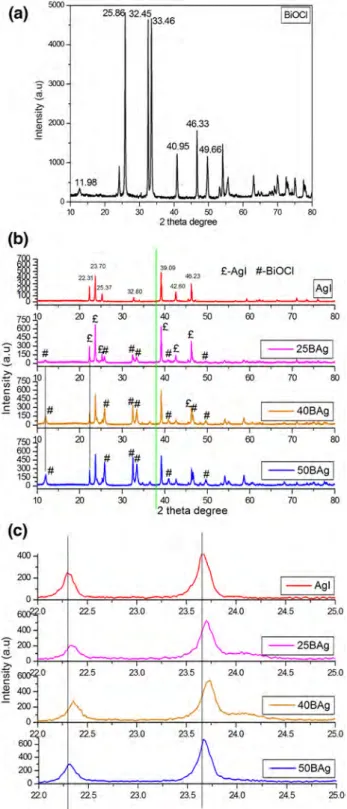
3.1 XRD analysisThe XRD result of AgI and BiOCl/AgI samples are provided in Fig. 1. All diffraction peaks are sharp that indicates well crystallite structure of the prepared samples. Characteristic diffraction peaks of BiOCl were observed at 2θ = 11.98°, 25.86°, 32.45°, 33.45°, 40.95°, 46.33°, 49.66°. These values correspond to the tetragonal structure of BiOCl with (001), (002), (110), (012), (112), (020), and (113) planes, respec-tively (Fig. 1a) [13].
Moreover, pure AgI shows sharp diffraction peaks at 2θ = 22.31°, 23.70°, 25.37°, 32.80°, 39.09°, 42.62° and 46.23° (Fig. 1) that corresponds to the (100), (002), (101), (102), (110), (103), (112) crystal planes of β-phase AgI crys-tal [14]. The peak intensity ratio of (110) to (001) planes for BiOCl was calculated as 2.32, 2.26 and 2.53 for 25BAg, 40BAg and 50BAg samples, respectively. It is possible that AgI particles were more dispersed onto (001) facet in the 40BAg sample (Fig. 1b).
It is clear that addition of BiOCl did not change the dif-fraction peaks of AgI in the AgI–BiOCl samples as com-pared with the standard AgI in the JPDS pattern. For the AgI–BiOCl samples, the intensity of diffraction peaks of BiOCl are gradually increased (Fig. 1b). The XRD patterns of the synthesized catalysts were evaluated with the standard card of Ag (JCPDS No. 04-0783). Metallic Ag (green line in Fig. 1b) was not obtained the prepared samples [15]. After producing BiOCl/AgI, the peaks of the composites remark-ably shifted to higher 2 theta angle with the increasing of BiOCl content, which confirms a strong interaction between AgI and BiOCl (Fig. 1c).
3.2 SEM analysis
All composites showed almost similar morphology that con-firms the co-existing of BiOCl and AgI (Fig. 2). Two types of shapes were observed in the composites samples. AgI par-ticles were collected on the surface of BiOCl. The surfaces of the composite samples were rough that presented higher sorption onto their surfaces, that is why efficient catalytic degradation occured. As shown in Fig. 2d, BiOCl particles have platelet morphology of 50–70 nm thickness with semi-uniform flat surfaces.
3.3 TEM analysis
Figure 3 shows TEM image AgI/BiOCl (40BAg) compos-ite. From Fig. 3a, it can be seen that the AgI and BiOCl were combined closely (Fig. 3a). BiOCl and AgI particles
were spherical and rods shapes. The EDX mapping images exhibits that AgI/BiOCl (40BAg) sample shows a uniform distribution of the chemical elements on their surfaces. Hence, it could conceivably be hypothesized that BiOCl and AgI co-exist in the composite photocatalyst with close interaction.
Fig. 1 XRD pattern of pure BiOCl (a), all samples (b) and shifting of 2θ degree (c)
Fig. 2 SEM images of the synthesized composite particles 25BAg (a), 40BAg (b), 50BAg (c)
(a) 5000 25. 32,4533.46
l
s
;
oc1
I
4000 : , :xxx, ~ z. ·;;; ~ 200) 46.33 ~ 40.95 49,66 1000 0 10 20 30 40 50 00 70 80 2 theta degree (b)I
"'"
£-Agl #-BiOCI Agl 750 50 60 70 60 600 £ 450 ~ 300 - -25BAg =! 150 # # ~ 0 -~ 75010 50 60 70 60 ~ 600 Q) 450c
300 - -408Ag 150 0 750 60 70 60 600 450 300 - -50BAg 150 0 10 20 30 140 50 60 70 60 2 theta degree(c)
400 1- Agll 23.0 24.0 24,5 25,0 - -25BAg ;,;-23.0 24.0 24.5 25.0 ·;;; C: Q) c l - 40BAgl 23.0 24.0 24,5 25,0 l- 50BAgl 22.0 22.S 23.0 23.5 24.0 24.S 25.o,3.4 Optical properties
The optical properties of catalysts play a major role in the photosensitization activity. UV–Vis analysis was performed between 200 and 800 nm spectral ranges to investigate the
optical and light-acting properties of the samples. Figure 4a presents the UV–Vis diffuse reflectance spectra of BiOCl, AgI and BiOCl/AgI. All samples (except BiOCl) absorbed the visible light of < 450 nm suggesting their broad utility under the visible light irradiation. Band gap values (Table 1)
Fig. 3 TEM image (a) and corresponding elemental mapping images (b, bı) of 40BAg nanoparticles
.
.
.
.
...
..
_.·.
.
.
.
.
:
r
r
·
·
:
::
·
,
.
::
,
.·
., . . . . : . . : ' :·. ·-· .... ' .1.
..
.
;.
·
.
'\ :~.
.
:-
.
-
,::
,
..
..
...
.
. . :..
..
.
·...
....
:
::_ ,• '•.
..
. .
..
.
.
. • .: ••• :. ' .- I' :· .. • ' ••...
.
.
: ~.
.. ·.· .Cl Kal
._..
..
Ag Kal
250nmBilal
250nm 250nm0 Kal
{b1)
250nmI Kal
( b1)
250nmof the samples were calculated using Eg= 1240
λ formula. The
band gap value of BiOCl is higher than the others.
As well known, crystalline structure and surface prop-erties can change the DRS results of a catalyst. With the
increasing of BiOCl content, slightly red shift occurs that can be seen in the spectrum of BiOCl/AgI composites that is in fact caused by the synergetic effect between BiOCl and AgI [16]. However, no noticeable differences were observed in the band gap values of the synthesized BiOCl/ AgI catalysts. The band gap value of the 40BAg sample is lower as compared to the values of other composites (Table 1). A possible explanation for this case can be oxy-gen vacancy that provides a new electronic state in the BiOCl, which acts as a trap to capture excited electrons. This phenomenon is useful to expand the absorption spec-trum to the visible light region [17].
In summary, the obtained band gap values of the BiOCl and AgI are smaller than that of BiOCl/AgI composites. Thus it can be suggested that BiOCl/AgI is suitable to excite its electrons under visible light that are required for the catalytic degradation of organic materials.
Furthermore, the band edge locations of BiOCl and AgI were calculated by using the following empirical formula:
where ECB and EVB is the valence and conduction band edge
potential, X are the electro negativities of BiOCl (X = 6.36) [18] and AgI (X = 5.48) [19]. Eg is the band gap energy of
the semiconductor while Ee is the energy of free electrons
on the hydrogen scale (about 4.5 eV). The estimated ECB and
EVB values were − 0.52 and 2.48 for AgI and − 0.39 and 3.92 for BiOCl respectively. Therefore, it can be proposed that BiOCl and AgI exhibit a matching interactive energy band structure. These observations support the efficient separation of the charges (electrons and holes) that are originated from AgI in the BiOCl/AgI catalyst [20].
3.5 PL analysis
To investigate the separation and recombination of the charge carriers in the synthesized samples with different BiOCl molar ratios, photoluminescence (PL) was meas-ured (Fig. 5) at room temperature. The BiOCl/AgI com-posites showed almost similar emission peaks with that of pure AgI. The PL absorbance intensity of AgI and BiOCl around 485 nm was higher in 40BAg sample (Fig. 5). As well known, PL reflects an impressive result to reveal migration, recombination and charge transfer efficiency. There are many reports where the higher PL intensity shows lower recombination of electron hole pairs that reduces the photocatalytic activity. However, sometime a surface defect and oxygen vacancy at the catalyst surface can cause higher PL intensity of photoluminescence and photocatalytic activity [21].
ECB=X − Ee−0.5Eg
EVB=X − Ee+0.5Eg
Fig. 4 UV-DRS spectra of the synthesized samples
Table 1 Band gaps and kinetic results of the catalysts
Photocatalyst Band gap (eV)
Visible light UV light k (min−1) (10−3) R2 k (min−1) (10−3) R2 Blank – 0.1 0.68 0.1 0.68 BiOCl 4.31 2.2 0.99 3.2 0.95 AgI 3.01 3.4 0.99 4.3 0.99 25Bag 2.93 4.2 0.99 6.1 0.98 40Bag 2.91 6.5 0.98 10.7 0.98 50BAg 2.92 4.6 0.98 8.8 0.99
50-,---,
45 40 35 30 a:: 25 '#. 20 10 5 200 (a) 400 300 400 500 600 Wavelenght (nm) 410 420 430 440 Wavelenght (nm) - BiOC1 - A!iJI - 25""'1 - 408 ... - 508Ag 700 800 450 4603.6 XPS analyses
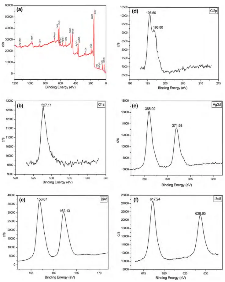
Figure 6 shows the high resolution XPS spectra of the 40BAg catalyst. The 40BAg sample contains Bi, Cl, O, Ag and I elements (Fig. 6a). An O 1s peak (Fig. 6b) at 527.11 eV belongs to O2- in the Bi–O bond in BiOCl [21]. Also the broad O 1s peak (Fig. 6c) indicates more than one chemical oxygen species [22]. Two XPS characteristic peaks (Fig. 6d) at 156.87 and 162.13 eV were Bi4f7/2 and 4f5/2
related to Bi3+ [23]. The peaks (Fig. 4e) detected at 371.93
and 365.92 eV represents Ag 3d3/2 and Ag 3d5/2 of Ag+ in
the 40BAg sample [24]. The binding energies of 628.65 and 617.24 eV were attributed to I3d3/2 and I3d5/2 respectively.
This confirms the presence of I− in AgI [20] (Fig. 6f). These
results confirm the pure BOCl/AgI composite to be used in the photocatalytic study.
3.7 Photocatalytic studies
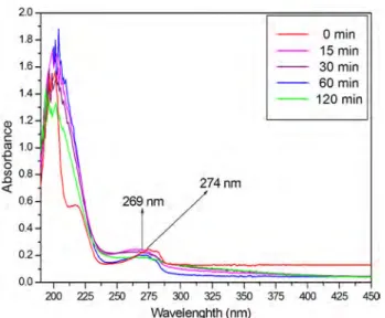
All photocatalytic studies were performed under UV–Vis-ible irradiation at room temperature and neutral pH. As well known, adsorption of the samples plays a major role in the degradation process. 0.1 g/50 mL of solid/liquid was added to a beaker where the concentration of 3-CP was 10 mgL− 1. This solution was kept in the dark for 60 min
to obtain adsorption/desorption equilibrium. Initially the absorption spectrum of 3-CP did not change until irradiated by UV–Visible light without catalyst (Fig. 7). The obtained absorption spectra of 3-CP presented a distinct band cen-tered around 269 nm. This band is related to the electronic transitions of the phenolic oxygen on the aromatic ring of 3-CP [25].
In 40BAg sample, similar absorption spectrum of 3-CP was observed in dark conditions. This confirmed that the
synthesized samples did not shift the absorption spectra of 3-CP at initial stages. During the photodegradation, a 300 W Xe lamp with cut off UV filter was used as visible light source. For UV light irradiation, a specially designed UV reactor was used that consists of a closed system hav-ing a Spectroline XX-15 N UV lamp that emits radiation at 260 nm with the intensity of 2 mW cm−2 and allows fixed
mixing and cooling. Once photocatalytic degradation had begun, 1 mL of sample was withdrawn and filtered to moni-tor degradation rates of 3-CP in a spectrophotometer. This process was repeated every 30 min. Photocatalytic degrada-tion of 3-CP was calculated using the following equadegrada-tion:
where Ao and At are the initial and final absorbance of 3-CP
at 274 nm for visible light and 269 nm for UV light irradi-ated samples.
According to the Beer–Lambert law, initial and final absorbance represent the initial (Co) and final (C)
concen-trations of 3-CP [26]. The obtained results showed that composite BiOCl/AgI catalyst was more active to degrade 3-CP than the pure BiOCl and AgI samples. The amount of BiOCl was changed up to 50% in the BiOCl/AgI compos-ites (Fig. 7), where 40% of BiOCl content in the compos-ite provided the highest photocatalytic activity. A possible explanation for this might be that more BiOCl content low-ers the electron transfer efficiency of the photo-generated electron–hole pairs. So the catalytic activity decreases under the visible light [27]. In addition, more crystalline defect is possible in structure of the 40BAg sample (40%) that is also consistent with data obtained in UV-DRS results. The improved catalytic performance of the catalysts can be con-nected to several factors such as BET surface area, absorp-tion ability, separaabsorp-tion of electron/hole pair oxygen vacancy etc. To explain the photocatalytic mechanism of the BiOCl/ AgI samples under UV–Visible irradiation, the band struc-tures of the BiOCl and AgI must be considered.
The visible light degraded 64.1% of 3-CP (10 mgL− 1),
whereas UV light degraded 71.4% of 3-CP (10 mgL− 1)
within 120 min for 40BAg sample. The pseudo-first order kinetic rate was used to correlate the experimental results (Fig. 8b, d). The first order kinetic rate k (1/min) for 3-CP degradation can be calculated by plotting ln(Co
C) versus time
(t). C0 is the initial concentration at zero time and C stands
for the concentration at certain time. The kinetic rate con-stant and regressions coefficient values are provided in Table 1. Infact, higher rate constant value represents higher degradation yield in a photocatalytic reaction [27]. The obtained rate constant value of 40BAg sample was higher than the other samples (0.0065 and 0.0107 min− 1 for visible
and UV irradiations respectively). These higher kinetic rate %Degradation =Co − C
Co ×100 =
Ao − At At ×100
Fig. 5 PL spectra of the synthesized catalysts
1000 - 8iOCI 900 -- Agl 258Ag - •oBAg 800 - 50BAg 700 ~600 '.J ~500 ~ ·~ 400 2 C: 300 200 100 0 300 350 400 450 500 550 600 Wavelength (nm)
Fig. 6 XPS spectra of 40Bag sample, a survey, b O1s, c Bi4f, d Cl2p, e Ag3d, f I3d 60000 10500 (a) !:c (d) 195.60 Cl2p 50000
.,
" ,n 10000 ~ 9500 40000i-u
196.80 q 9000 " 30000 :£! 8500 "'ii "'I
"' u Ii () u 20000 800) 751XJ 10000 7000 0 6500 1200 1000 800 600 400 200 0 190 195 200 205 210 215Binding Energy (eV) Binding Energy (eV)
13000 18000 (b) I01sI (e) 365.92 IAg3dl 1251XJ 16000 12000 14000 371.93 11500 12000 "' 11000
"'
0 <) 10500 10000 10000 8000 9500 6000 9000 520 525 530 535 540 545 365 370 375 380Binding Energy (eV)
Binding Energy (eV)
40000 26000 (c) 156.87 IBi4fl (f) 61724 I3d5 35000 24000 30000 162.13 22000 25000 20000 20000 18000
"'
(/) <)o
16000 15000 14000 10000 12000 5000 10000 0 8000 155 160 165 170 615 620 625 630constants of 40BAg sample show efficient degradation than the others.
The band structure of BiOCl/AgI composites is given in Fig. 9. The obtained VB and CB band edge potential of BiOCl are 3.92 and − 0.39 eV while the VB and CB band potential of the AgI are 2.48 and − 0.52, respectively. Under the visible light irradiation (λ ≥ 405 nm), only the VB elec-trons of the AgI were excited to its CB level. The excited electrons of AgI transferred to the CB level of BiOCl due to their matching band structure. The standard redox potential of O2∕ ⋅ O
−
2 is approximately − 0.33 [28]. Therefore, transfer
of electrons from the CB level of AgI to the BiOCl enables the release of superoxide radicals (⋅O−
2
) by reducing (O
2
) . Also, the standard redox potential of H2O∕OH⋅ is about
2.38 eV that confirms that the holes (h+) on the AgI surface
oxidizes H2O to ⋅OH radical.
The VB electrons of BiOCl are not excited under vis-ible light due to higher band gap, however it plays as an electron trapping center to improve the separation efficiency of electron hole pairs that are originated from AgI catalyst
Fig. 7 The absorption spectra of 3-CP under UV light at different degradation time
Fig. 8 Photocatalytic degradation of 3-CP and ln (C0/C) as function of time using the catalysts under visible light (a, b), UV light (c, d)
2.0 1.8 0 min 15 min 1.6 30 min 60 min 1,4 120 min Q) 1.2 0 C: (1j .0 1.0 0 _2 0.8 274nm <( 0.6 0.4 0.2 0,0 200 225 250 275 300 325 350 375 400 425 450 Wavelenghth (nm)
(a)
1.0(c)
1.0 0.9 0.8 Light off 0.8 0.7 0.6 0.6 0 r,,2_° 0.5 Q u u 0.4 Light on 0.4 0.3 - -s1ank - -Blank .-..a;ocI --+-BiOCI 0.2 - - -Agl 0,2 - -Agl - -258Ag - -258Ag 0.1 408Ag 40BAg - -soeAg - -soBA9 0.0 0.0 -60 --40 -20 0 20 40 60 80 100 120 -60 -30 0 30 60 90 120Time (min) Time (min)
(b)
(d)
1,6 • Blank •Blank 0.9 1.4 0.8 1.2 0.7 0.6 Zr u u" 0.5 J'0.8 "ff. £ 0.4 0.6 0.3 0.4 0.2 0.1 0.2 0 0 0 20 40 60 80 100 120 0 20 40 60 80 100 120 Time (min) Time(min)(Fig. 9). During this process, AgI particles intercept the photo-induce electrons by interstitial Ag+ to reveal metallic
Ag [20] that improved the catalytic performance of 40BAg catalyst under visible light. Photodegrading of 3-CP under UV irradiation was higher than the visible light. 40BAg similarly exhibited more catalytic activity under both UV and visible irradiation.
From the above discussion, one can understand the fol-lowing points:
• It is possible that these results are originated from more excited electrons in both VB level of BiOCl / AgI and transferring of the holes in the VB level of BiOCl (Fig. 9).
• When 3-CP adsorbs on the catalyst surface, the electrons in the valence band (VB) of BiOCl and AgI excites to their defect level that lead to PL result. This level exhib-its extra hole h+ in the BiOCl/AgI structure. The oxygen
vacancies V0 can capture a hole (h+
)
in the defect level to transform V+
0 species [29]. These processes causes
effi-cient separation of electron hole pairs in combination.
• Holes (h+)
on the BiOCl and AgI can oxidize Cl− ions
to Cl⋅ and I− ions to I⋅ . These radicals can oxidize 3-CP
into CO2 and H2O. Thus, these coupling radicals shows efficient catalytic activity of the composite BiOCl/AgI samples [23].
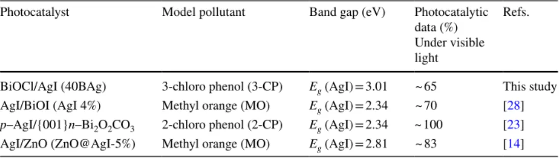
Table 2 presents a comparison of photocatalytic degrada-tion yield of AgI based composites. It is clear that AgI based composites exhibited efficient catalytic activity of degrada-tion for some organic pollutant under visible light irradia-tion. The obtained degradation results can be related to the efficient inhibition of recombination rate of electron/hole pairs and surface plasmon resonance (SPR) of metallic Ag.
3.8 Mechanism of 3‑CP degradation over BiOCl/AgI
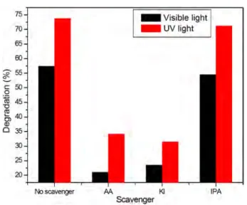
Radical reactive species (h+
, O⋅− 2 and OH
⋅) play an active role
to decompose organic pollutants. To evaluate the main reac-tive species in the 3-CP decomposition, ascorbic acid (AA), potassium iodide (KI) and isopropyl alcohol (IPA) (each 1 mmol L− 1) were used as (O⋅−
2
) , (h+
) and (OH⋅) scavengers
in the BiOCl/AgI/3-CP system (Fig. 9). The results showed that AA and KI have strongly suppressed the catalytic per-formance of 40BAg sample under both visible and UV light. These findings suggest that the main reactive species for 3-CP degradation over BiOCl/AgI catalyst are O⋅−
2 and h +
(Fig. 10).
4 Conclusion
BiOCl/AgI composites were successfully synthesized by in situ precipitation technique. The photocatalytic activity of the composites was evaluated using 3-CP under visible and UV irradiations. BiOCl/AgI composites showed more catalytic activity than pure BiOCl and AgI that can be attrib-uted to the low recombination rate of electron/hole pairs, (Cl−) and (I−) ions to produce (Cl·) and (I·) radicals. BiOCl
was found as the electron trapping center under visible light. Photo-generated superoxide radicals and holes were main active species under UV and Visible light. The composites degraded 3-CP with excellent yields. BiOCl/AgI composites are new candidates where the photodegradation of organic pollutants is required. These photocatalysts should be further explored against other water soluble organic pollutants.
Fig. 9 Schematic illustration of photocatalytic mechanism of 40BAg sample under visible light
Table 2 Comparing
photocatalytic degradation yield of AgI based composites
Photocatalyst Model pollutant Band gap (eV) Photocatalytic
data (%) Under visible light
Refs.
BiOCl/AgI (40BAg) 3-chloro phenol (3-CP) Eg (AgI) = 3.01 ~ 65 This study
AgI/BiOI (AgI 4%) Methyl orange (MO) Eg (AgI) = 2.34 ~ 70 [28] p–AgI/{001}n–Bi2O2CO3 2-chloro phenol (2-CP) Eg (AgI) = 2.34 ~ 100 [23]
AgI/ZnO (ZnO@AgI-5%) Methyl orange (MO) Eg (AgI) = 2.81 ~ 83 [14]
e e
Defect levelAcknowledgements This study has been supported by Mugla Sitki Kocman University Coordination of Scientific Research with 15/139.
References
1. L.M.B. Batista, A.J. dos Santos, D.R. da Silva, A.P. de Melo Alves, S. Garcia-Segura, C.A. Martinez-Huitle, Sci. Total Envi-ron. 596, 79–86 (2017)
2. F. Han, V.S.R. Kambala, M. Srinivasan, D. Rajarathnam, R. Naidu, Appl. Catal. A 359, 25–40 (2009)
3. G. Zhang, Y. Tan, Z. Sun, S. Zheng, J. Environ. Chem. Eng. 5(1), 1196–1204 (2017)
4. J. Jiang, H. Wang, X. Chen, S. Li, T. Xie, D. Wang, Y. Lin, J. Colloid. Int. Sci. 494, 130–138 (2017)
5. B.R. Cruz-Ortiz, J.W. Hamilton, C. Jablos, L. Diaz-Jimenez, D.A. Cortes-Hernandez, P.K. Sharma, M. Castro-Alferez, P. Fernandez-Ibanez, P.S.M. Dunlop, J.A. Byrne, Chem. Eng. J. 316, 179–186 (2017)
6. H. Kono, R. Kusumoto, J. Water Process. Eng. 7, 83–93 (2015) 7. J. Yao, D. Wen, J. Shen, J. Wang, J. Water Process. Eng. 11,
98–103 (2016)
8. A. Fujishima, T.N. Rao, D.A. Tryk, J. Photochem. Photobiol. C
1(1), 1–21 (2000)
9. Y. Li, Y. Tian, R. Zhang, L. Ma, C. Zhou, X. Tian, Inorg. Chim. Acta. 439, 123–129 (2016)
10. J. Henle, P. Simon, A. Frenzel, S. Scholz, S. Kaskel, Chem. Mater.
19(3), 366–373 (2007)
11. A.R. He, S. Cao, P. Zhou, J. Yu, Chin. J. Catal. 35(7), 989–1007 (2014)
12. S. Fang, C. Ding, Q. Liang, Z. Li, S. Xu, Y. Peng, D. Lu, J. Alloy. Compd. 684, 230–236 (2016)
13. Z. Song, X. Dong, N. Wang, L. Zhu, Z. Luo, J. Fang, C. Xiong, Chem. Eng. J. 317, 925–934 (2017)
14. H. Huang, N. Huang, Z. Wang, G. Xia, M. Chen, L. He, C. Ren, J. Colloid Interface Sci. 502, 77–88 (2017)
15. Z. Xiang, Y. Wang, P. Ju, Y. Long, D. Zhang, J. Alloy Compd.
721, 622–627 (2017)
16. L. Chen, D. Jiang, T. He, Z. Wu, M. Chen, CrystEngComm
15(37), 7556–7563 (2013)
17. S. Zhao, Y. Zhang, Y. Zhou, K. Qiu, C. Zhang, J. Fang, X. Sheng, J. Photochem. Photobiol. A 350, 94–102 (2018)
18. H. Cheng, B. Huang, Y. Dai, Nanoscale 6(4), 2009–2026 (2014) 19. J. Zhang, Z. Ma, J. Taiwan Inst. Chem. E 81, 225–231 (2017) 20. H. Ye, H. Lin, J. Cao, S. Chen, Y.J. Chen, Mol. Catal. A 397,
85–92 (2015)
21. A. Vaizoğullar, Asia-Pac. J. Chem. Eng. 13, 1–10 (2018) 22. H. Cheng, B. Huang, Y. Dai, Nanoscale 6, 2009–2026 (2014) 23. L. Zhang, C. Hu, H. Ji, Appl. Catal. B 205, 34–41 (2017) 24. H. Xu, J. Yan, Y. Xu, Y. Song, H. Li, J. Xia, H. Wan, Appl. Catal.
B 129, 182–193 (2013)
25. N. Salah, A. Hameed, M. Aslam, S.S. Babkair, F.S. Bahabri, J. Environ. Manag. 177, 53–64 (2016)
26. S. Suwanboon, S. Klubnuan, N. Jantha, P. Amornpitoksuk, P. Ban-grak, Mater. Lett. 115, 275–278 (2014)
27. S. Fang, C. Ding, Q. Liang, Z. Li, Y. Xu Seng, D. Lu, J. Alloy. Compd. 684, 230–236 (2016)
28. Q. Yang, J. Huang, J. Zhong, J. Chen, J. Li, S. Sun, Curr. Appl. Phys. 171, 1202–1207 (2017)
29. A. Tabib, W. Bouslama, B. Sieber, A. Addad, H. Elhouichet, M. Férid, R. Boukherrou, Appl. Surf. Sci. 396, 1528–1538 (2017)
Fig. 10 Effect of scavenger on the 3-CP degradation over BiOCl/ZnO
(40BAg) 75 70 65 60 C 50 0 :.::, ro 45 ,:, fl: 40 ~ 0 35 30 25 20 No scavenger - Visible light - uvnght AA Kl IPA Scavenger