Advances in Nano Research, Vol. 6 No. 3 (2018) 219-242 DOI: https://doi.org/10.12989/anr.2018.6.3.219
Copyright © 2018 Techno-Press, Ltd.
http://www.techno-press.org/?journal=anr&subpage=5 ISSN: 2287-237X (Print), 2287-2388 (Online)
Bending of a cracked functionally graded nanobeam
Şeref Doğuşcan Akbaş
Department of Civil Engineering, Bursa Technical University, Bursa, Turkey (Received March 29, 2017, Revised May 24, 2018, Accepted July 17, 2018)
Abstract. In this study, static bending of an edge cracked cantilever nanobeam composed of functionally graded material (FGM) subjected to transversal point load at the free end of the beam is investigated based on modified couple stress theory. Material properties of the beam change in the height direction according to exponential distributions. The cracked nanobeam is modelled using a proper modification of the classical cracked-beam theory consisting of two sub-nanobeams connected through a massless elastic rotational spring. The inclusion of an additional material parameter enables the new beam model to capture the size effect. The new non-classical beam model reduces to the classical beam model when the length scale parameter is set to zero. The considered problem is investigated within the Euler-Bernoulli beam theory by using finite element method. In order to establish the accuracy of the present formulation and results, the deflections are obtained, and compared with the published results available in the literature. Good agreement is observed. In the numerical study, the static deflections of the edge cracked FGM nanobeams are calculated and discussed for different crack positions, different lengths of the beam, different length scale parameter, different crack depths, and different material distributions. Also, the difference between the classical beam theory and modified couple stress theory is investigated for static bending of edge cracked FGM nanobeams. It is believed that the tabulated results will be a reference with which other researchers can compare their results.
Keywords: open edge crack; modified couple stress theory; functionally graded materials; nanobea
1. Introduction
With the great advances in technology in recent years, micro and nano structures have found many applications. In these structures, micro beams and micro tubes are widely used in micro- and nano electromechanical systems (MEMS and NEMS) such as sensors (Zook et al. 1992, Pei et al. 2004), actuators (Senturia 1998, Rezazadeh et al. 2006). In investigation of micro and nano structures, the classical continuum mechanics is not capable of explanation of the size-dependent behaviors. Nonclassical continuum theories such as higher order gradient theories and the couple stress theory are capable of explanation of the size dependent behaviors which occur in micro/nano-scale structures.
Functionally graded materials (FGMs) are a new generation of composites where the volume fractions of the FGM constituents vary gradually, giving a non-uniform nanostructure with continuously graded macro properties such as elasticity modulus, density, heat conductivity, etc.. With the advance of the material science, micro–electro-mechanical systems are the new field in
Corresponding author, Ph.D., Associate Professor, E-mail: [email protected]
Şeref Doğuşcan Akbaş
which FGMs have been utilized to achieve the desired performance. With the development of technology, FGMs are initialized to be used in micro/nano structural systems.
In recent years, functionally graded materials have been widely used in micro/nanoelectro-mechanical
gradient a systems (MEMS/NEMS), such as the components in the form of shape memory alloy thin films with a global thickness in micro- or nano-scale (Fu et al. 2003, Witvrouw and Mehta 2005, Lü et al. 2009), electrically actuated MEMS devices (Hasanyan et al. 2008, Mohammadi-Alasti et al. 2011, Zhang and Fu 2012), and atomic force microscopes (AFMs) (Rahaeifard et al. 2009). In all these applications, the thickness of the microstructures (i.e., microbeams or microplates) is typically on the order of microns and sub-microns. At the present time, the experimental investigations of the micro materials are still a challenge because of difficulties confronted in the micro scale. Therefore, mechanical theories and atomistic simulations have been used for micro structural analysis. The process of the atomistic simulations is very difficult and takes much time. So, continuum theory is the most preferred method for the analysis of the micro and nano structures. Classical continuum mechanics does not contain the size effect, because of its scale-free character. The nonlocal continuum theory initiated by Eringen (1972) has been widely used to mechanical behavior of nano-micro structures.
The size effect plays an important role on the mechanical behavior of micro/nano structures at the nanometer scale that the classic theory has failed to consider when the size reduces from macro to nano (Toupin 1962, Mindlin and Tiersten 1962, Mindlin 1963, Fleck and Hutchinson 1993, Yang et al. 2002, Lam et al. 2003). Therefore, higher-order theories modified couple stress theory and modified strain re used in the mechanical model of the nano-micro structures (Yang et al. 2002, Lam et al. 2003).
The determination of the nano-structural material length scale parameters is very difficult experimentally. So, Yang et al. (2002) proposed the modified couple stress theory in which the strain energy has been shown to be a quadratic function of the strain tensor and the symmetric part of the curvature tensor, and only one length scale parameter is included. After this, the modified couple stress and the strain gradient elasticity theories have been widely applied to static and dynamic analysis of beams (Park and Gao 2006, Ma et al. 2008, Kong et al. 2008, Asghari et al. 2010, Wang 2010, Şimşek 2010, Kahrobaiyan et al. 2010, Xia et al. 2010, Ke et al. 2011, Akgöz and Civalek 2012, Ansari et al. 2012, Gürses et al. 2012, Wang et al. 2013, Kocatürk and Akbaş 2013, Kong 2013, Ghayesh et al. 2013, Daneshmehr et al. 2013, Akgöz and Civalek 2013). More recently, Darijani and Mohammadabadi (2014) proposed a new deformation beam theory for static and dynamic analysis of microbeams which includes unknown functions takes into account shear deformation and satisfies both of shear and couple-free conditions on the upper and lower surfaces of the beam based on a modified couple stress theory. Tang et al. (2014) analyzed a theoretical model for flexural vibrations of microbeams in flow with clamped-clamped ends based on a modified couple stress theory. Sedighi et al. (2014) investigated the dynamic pull-in instability of vibrating micro-beams undergoing large deflection under electrosatically actuation. Farokhi and Ghayesh (2015) studied the three-dimensional motion characteristics of perfect and imperfect Timoshenko microbeams under mechanical and thermal forces based on the modified couple stress theory. Ansari et al. (2015) studied an exact solution of vibrations of postbuckled microscale beams based on the modified couple stress theory. Dai et al. (2015) developed a new nonlinear theoretical model for cantilevered microbeams and to explore the nonlinear dynamics based on the modified couple stress theory, taking into account of one single material length scale parameter. Farokhi and Ghayesh (2015) investigated the three-dimensional
Bending of a cracked functionally graded nanobeam
motion characteristics of perfect and imperfect Timoshenko microbeams under mechanical and thermal forces.
In recent years, various investigations have been carried out to study of static and vibration behavior of the Functioanlly graded (FGM) micro/nano beams; (Ansari et al. 2011, 2013a, b, Liu and Reddy 2011, Reddy 2011, Ke et al. 2011, Talab et al. 2012, Nateghi and Salamat-Talab 2013, Akgöz and Civalek 2013, Şimşek and Reddy 2013a, Zamanzadeh et al. 2013, Şimşek
et al. 2013, Ansari et al. 2014a, b), buckling (Ansari et al. 2012, 2013c, d, Şimşek and Reddy
2013b, Wang et al. 2014, Akgöz and Civalek 2014, 2015a, b, 2016) of the FGM beams in which the nonclassical continuum mechanics have been employed. Berrabah et al. (2013) examined bending, buckling and free vibration of nanobeams by using unified nonlocal shear deformation theory. Tagrara et al. (2015) presented a trigonometric refined beam theory for the bending, buckling and free vibration analysis of carbon nanotube-reinforced composite beams resting on elastic foundation. Zemri et al. (2015) investigated nonlocal shear deformation beam theory for bending, buckling, and vibration of functionally graded nanobeams using the nonlocal differential constitutive relations of Eringen. Aissani et al. (2015) presented a new nonlocal hyperbolic shear deformation beam theory for the static, buckling and vibration of nanoscale-beams embedded in an elastic medium. Akbaş (2016b) investigated forced vibration of viscoelastic nano scale beams. Akbaş (2016c) presented static analysis of nanoplates by using differantial quadrature method. Ehyaei et al. (2016) examined effect on free vibration characteristics of functionally graded size-dependent nanobeams by using a semi analytical differential transform method. Ebrahimi and Barati (2016a, b) investigated buckling of functionally graded nanobeams. Eltaher et al. (2016) studied the effects of thermal load and shear force on the buckling of nanobeams. Akbaş (2017a) analyzed forced vibration of functionally graded nanobeams.
Micro and nano structures are subjected to destructive effects in the form of initial defects within the material or caused by fatigue or stress concentration, for example, crack occurrence in ZnO nano-rods is due to thermal fabrication process (Fang and Chang 2003, Fang et al. 2003). As a result of destructive effects, cracks occur in the structural elements. It is known that cracks cause local flexibility and changes in structural stiffness. Understanding the mechanical behaviour edge-cracked structures and detection of cracks are very important for safety of nano structures.
In the literature, the studies of the cracked micro-nano structures are as follows; Loya et al. (2009) studied the flexural vibrations of cracked micro- and nanobeams with the rotational and linear spring model based on nonlocal elasticity. Hasheminejad et al. (2011) investigated the flexural vibrations of cracked micro- and nanobeams in the presence of surface effects with the rotational linear spring model. Hsu et al. (2011) analysed longitudinal vibration of cracked nanobeams based on nonlocal elasticity theory. Torabi and Nafar Dastgerdi (2012) studied with the free transverse vibration of cracked nanobeams modeled based on Eringen’s nonlocal elasticity theory and Timoshenko beam theory with a rotational spring. Liu et al. (2013) investigated Vibration behavior of a cracked Euler-Bernoulli micro-cantilever beam under coupling action of nonlinear electrostatic force and squeeze film damping effect. Hosseini-Hashemi et al. (2014) investigated the dynamics of thin and thick cracked nanobeams with surface effects. Tadi Beni et
al. (2015) examined the transverse vibration of cracked nano-beam based on modified couple
stress theory with rotational spring model. Akbaş (2016a) investigated static analysis of cracked micro beams. Shaat et al. (2016) investigated vibration analysis of Cracked Nano- Beams made of Nanocrystalline Materials. Akbaş (2017b) studied free vibration of edge cracked functionally graded microsbeams. Akbaş (2018) investigated forced vibration analysis of cracked functionally graded microbeams.
Şeref Doğuşcan Akbaş
This paper examines static bending of an edge cracked FGM cantilever nanobeam based on the modified couple stress theory. The nanobeam is subjected to transversal point load at the free end of the beam. Material properties of the beam change in the height direction according to exponential distributions. The cracked beam is modelled using a proper modification of the classical cracked-beam theory consisting of two sub-beams connected through a massless elastic rotational spring. The considered problem is investigated within the Euler-Bernoulli beam theory by using finite element method. This nanobeam model incorporates the material length scale parameter which can capture the size effect. In order to establish the accuracy of the present formulation and results, the deflections are obtained, and compared with the published results available in the literature. Good agreement is observed. In the numerical study, the static deflections of the edge cracked FGM nanobeams are calculated and discussed for different crack positions, different lengths of the beam, different length scale parameter, different crack depths, and different material distributions. Also, the difference between the classical beam theory and modified couple stress theory is investigated for static bending of edge cracked FGM nanobeams. It is believed that the tabulated results will be a reference with which other researchers can compare their results.
2. Theory and formulations
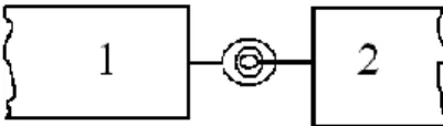
Consider a cantilever FGM nanobeam of length L, width b, height h, containing an edge crack of depth a located at a distance L1 from the left end, as shown in Fig. 1. It is assumed that the crack
is perpendicular to beam surface and always remains open. The beam is subjected to a point load (Q) in the transverse direction as seen from Fig. 1.
The material properties of the FGM nanobeam P, i.e., Young’s modulus E, Poisson’s ratio ν and shear modulus G vary continuously in the thickness direction (Y axis) according to exponential distributions as follows
𝑃 𝑌 = 𝑃0𝑒𝛽𝑌 (1)
where 𝑃0 is the material properties at the midplane (Y = 0) of the beam. 𝛽 is a constant characterizing the gradual variation of the material properties along thickness direction. When 𝛽 =
0, the material of the beam is homogeneous. According to Eq. (1) that when Y = h/2, P = PB (PB is
the material properties of the bottom). When Y = ‒h/2, P = PT (PT is the material properties of the
top).
2.1 The modified couple stress theory
The strain energy density for a linear elastic material which is a function of both strain tensor
Fig. 1 A cantilever FGM nanobeam with an open edge crack subjected to a point load 222
Bending of a cracked functionally graded nanobeam
and curvature tensor is introduced by Yang et al. (2002) for the modified couple stress theory
𝑈 = 𝜎: 𝜀 + 𝑚: 𝜒
𝑉
𝑑𝑉 (2)
where σ is the stress tensor, ε is the strain tensor, m is the deviatoric part of the couple stress tensor,
χ is the symmetric curvature tensor, defined by
𝜎 = 𝜆 𝑡𝑟 𝜀 𝐼 + 2𝜇𝜀 (3) 𝜀 =1 2 ∇𝑢 + ∇𝑢 𝑇 (4) 𝑚 = 2𝑙2𝜇 𝜒 (5) 𝜒 =1 2 ∇𝜃 + ∇𝜃 𝑇 (6)
where λ and μ are Lame’s constants, l is a material length scale parameter which is regarded as a material property characterizing the effect of couple stress. The material length scale is a size effect parameter which has important role on the structural behavior of micro/nano structures, because the dimensions of these structures are smaller than the atomic/molecular distances. However, classical continuum mechanics does not contain the material length scale parameter, because of its scale-free character. u is the displacement vector and θ is the rotation vector, given by
𝜃 =1
2curl 𝑢 (7)
The parameters λ and μ in the constitutive equation are given by
𝜆 𝑌 = 𝐸 𝑌 𝜈 𝑌
1 + 𝜈 𝑌 1 − 2𝜈 𝑌 , 𝜇 𝑌 =
𝐸 𝑌
2 1 + 𝜈 𝑌 (8)
Where E is the modulus of elasticity and ν is the Poisson’s ratio and their dependence on Y coordinate are given by Eq. (1).
2.2 Governing equations of FGM nanobeams
According to the coordinate system (X, Y, Z) shown in Fig. 1, based on Euler-Bernoulli beam theory, the axial and the transverse displacement field are expressed as
𝑢 𝑋, 𝑌 = 𝑢0 𝑋 − 𝑌𝜕𝑣0 𝑋
𝜕𝑋 (9)
𝑣 𝑋, 𝑌, 𝑡 = 𝑣0 𝑋, 𝑡 (10)
Şeref Doğuşcan Akbaş
𝑤 𝑋, 𝑌, 𝑡 = 0 (11)
where u, v, w are x, y and z components of the displacements, respectively. Also, u0 and v0 are the
axial and the transverse displacements in the mid-plane.
Because the transversal surfaces of the beam is free of stress, then
𝜎𝑧𝑧 = 𝜎𝑦𝑦 = 0 (12)
By using Eqs. (3), (8) and (9) and strain- displacement relation can be obtained
𝜀𝑥𝑥 =𝜕𝑢 𝜕𝑋= 𝜕𝑢0 𝑋 𝜕𝑋 − −𝑌 𝜕2𝑣 0 𝑋 𝜕𝑋2 (13a) 𝜀𝑦𝑦 = 𝜀𝑧𝑧 = 𝑌 𝜈 𝑌 𝜕2𝑣0 𝑋 𝜕𝑋2 (13b) 𝜀𝑥𝑧 = 𝜀𝑦𝑧 = 𝜀𝑥𝑦 = 0 (13c)
By using Eqs. (7), (9), (10) and (11) 𝜃𝑧 =𝜕𝑣0 𝑋
𝜕𝑋 , 𝜃𝑥 = 𝜃𝑦 = 0 (14)
Substituting Eq. (14) into Eq. (6), the curvature tensor χ can be obtained as follows
𝜒𝑥𝑧 =1
2 𝜕2𝑣
0 𝑋
𝜕𝑋2 , 𝜒𝑥𝑥 = 𝜒𝑥𝑦 = 𝜒𝑦𝑦 = 𝜒𝑦𝑧 = 𝜒𝑧𝑧 = 0 (15)
According to Hooke’s law, constitutive equations of the FGM nanobeam are as follows
𝜎𝑥𝑥 = 𝐸(𝑌)𝜀𝑥𝑥 = 𝐸(𝑌) 𝜕𝑢0 𝑋
𝜕𝑋 − 𝑌
𝜕2𝑣 0 𝑋
𝜕𝑋2 (16)
Where σxx and εxx are normal stresses and normal strains in the X direction, respectively.
Substituting Eq. (15) into Eq. (5), the couple stress tensor can be obtained as follows 𝑚𝑥𝑧 = 𝑙2𝜇(𝑌)1
2
𝜕2𝑣0 𝑋
𝜕𝑋2 (17a)
𝑚𝑥𝑥 = 𝑚𝑥𝑦 = 𝑚𝑦𝑦 = 𝑚𝑦𝑧 = 𝑚𝑧𝑧 = 0 (17b)
where μ is shear modulus which is defined by Eq. (8). Based on Euler-Bernoulli beam theory, the
elastic strain energy (Ui) of the FGM nanobeam is expressed as
𝑈𝑖 =1 2 𝜎𝑖𝑗 𝜀𝑖𝑗 + 𝑚𝑖𝑗 𝜒𝑖𝑗 𝐴 𝑑𝐴 𝑑𝑋 𝐿 0 (18) 224
Bending of a cracked functionally graded nanobeam
By substituting Eqs. (16), (17), (13a) and (15) into Eq. (18), elastic strain energy (Ui) can be
rewritten as follows 𝑈𝑖=1 2 𝐴11 𝜕𝑢0 𝜕𝑋 2 − 2𝐵11 𝜕𝑢0 𝜕𝑋 𝜕2𝑣 0 𝜕𝑋2 + 𝐷11 𝜕2𝑣 0 𝜕𝑋2 2 +1 4𝑙 2𝐴 55 𝜕2𝑣 0 𝜕𝑋2 2 𝑑𝑋 𝐿 0 (19) Where 𝐴11, 𝐵11, 𝐷11 = 𝐸 𝑌 (1, 𝑌, 𝑌2)𝑑𝐴 𝐴 , 𝐴55 = 𝜇 𝑌 𝑑𝐴 𝐴 (20)
The potential energy of the external load can be written as
𝑊 = 𝑄 𝑣0 𝑋 = 𝐿 (21)
The considered problem is solved by using finite element method.
Total nodal displacements q which is written for a two-node beam element, each node has three degrees of freedom, shown in Fig. 2 are defined as follows
𝑞 e = 𝑢𝑖 𝑒 , 𝑣𝑖 𝑒 , 𝜃𝑖 𝑒 , 𝑢𝑗 𝑒 , 𝑣𝑗 𝑒 , 𝜃𝑗 𝑒 𝑇 (22) The displacement field of the finite element is expressed in terms of nodal displacements as follows 𝑢 𝑒 𝑋 = 𝜑1 𝑈 𝑋 𝑢𝑖+ 𝜑2 𝑈 𝑋 𝑢𝑗 = 𝜑 𝑈 𝑢 𝑢𝑖 𝑗 = 𝜑 𝑈 𝑞 𝑈 (23) 𝑣 𝑒 𝑋 = 𝜑1 𝑉 𝑋 𝑣𝑖+ 𝜑2 𝑉 𝑋 𝜃𝑖+ 𝜑3 𝑉 𝑋 𝑣𝑗 + 𝜑4 𝑉 𝑋 𝜃𝑗 𝜑 𝑉 𝑣𝑖 𝜃𝑖 𝑣𝑗 𝜃𝑗 = 𝜑 𝑉 𝑞 𝑉 (24)
Where ui, vi and θi are axial displacements, transverse displacements and slopes at the two end
nodes of the beam element, respectively. 𝑗𝑖(𝑈) and 𝑗𝑖(𝑉) are Hermitian shape functions for axial and transverse degrees of freedom, respectively, which are given in Appendix.
By substituting Eqs. (23) and (24) into Eq. (19), energy functions can be rewritten as follows
Fig. 2 A two-node beam element
Şeref Doğuşcan Akbaş 𝑈𝑖 =1 2 𝐴11 𝜕𝜑 𝑈 𝜕𝑋 𝑞 𝑈 2 − 2𝐵11 𝜕𝜑 𝑈 𝜕𝑋 𝑞 𝑈 𝜕2𝜑 𝑉 𝜕𝑋2 𝑞 𝑉 +𝐷11 𝜕 2𝜑(𝑉) 𝜕𝑋2 𝑞 𝑉 2 + 1 4𝑙 2𝐴 55 𝜕2𝜑(𝑉) 𝜕𝑋2 𝑞 𝑉 2 𝑑𝑋 𝐿 0 (25)
The total potential energy of the beam is given by
Π = 𝑈 − 𝑊 (26)
According to the minimum total potential energy principle, nodal displacements 𝑞 which correspond to the minimum of the total potential energy are determined by the conditions
𝜕П
𝜕𝑞 = 0 (27)
Differentiation of П in respect to nodal displacements 𝑞 produces the following equilibrium equations for a finite element
𝐾 𝑞 = 𝐹 (28)
where, [K] is the stiffness matrix and {F} is the load vector. The components of the stiffness matrix [K] 𝐾 = 𝐾𝐴 𝐾𝐵 𝐾𝐵 T 𝐾𝐷 (29) Where 𝐾𝐴 = 𝐴 11 𝐿e 0 𝜕𝜑(𝑈) 𝜕𝑋 𝑇 𝜕𝜑 (𝑈) 𝜕𝑋 𝑑 (30a) 𝐾𝐵 = − 𝐵 11 𝐿e 0 𝜕2𝜑(𝑉) 𝜕𝑋2 𝑇 𝜕𝜑 (𝑈) 𝜕𝑋 𝑑 (30b) 𝐾𝐷 = 𝐷 11 + 1 4𝑙 2𝐴 55 𝐿e 0 𝜕2𝜑(𝑉) 𝜕𝑋2 𝑇 𝜕 2𝜑(𝑉) 𝜕𝑋2 (30c)
Where Le indicates the length of the finite beam element.
The load vector {F} is expressed as
𝐹 = 𝜑(𝑋) 𝑇 𝑄 (31)
2.3 Crack modeling
The cracked FGM nanobeam is modelled using a proper modification of the classical cracked-beam theory consisting of two sub-cracked-beams connected through a massless elastic rotational spring
Bending of a cracked functionally graded nanobeam shown in Fig. 3.
The bending stiffness of the cracked section kT is related to the flexibility G by
𝑘𝑇 = 1
𝐺= 0 (32)
The cracked section’s flexibility G can be derived from Broek’s approximation (Broek 1986)
1 − 𝜈2 𝐾 𝛪2 𝐸(𝑎) = 𝑀2 2 𝑑𝐺 𝑑𝑎 (33)
where M is the bending moment at the cracked section, a is the crack depth, KI is the stress
intensity factor (SIF) under mode I bending load (which is a function of the geometry, loading, and material properties), and v indicates Poisson’s ratio (which is taken as constant since its influence on the SIF is quite limited (Erdoğan and Wu 1997)). For an FGM strip with an open edge crack under bending, the analytical solution along with the expression of SIF has been given Yu and Chu (2009), which was obtained from the data given by Erdogan and Wu (1997) through the Lagrange interpolation technique
𝐾𝐼=6𝑀
𝜋𝑏 𝜋𝑎 𝐹 𝐸𝑅, 𝑎/ℎ (34)
where ER is the ratio of Young’s modulus at the bottom to the top surface of the beam (EB/ET), and
F is an unknown function of two independent variables, given as (Yu and Chu 2009)
𝐹 𝐸𝑅, 𝑎 ℎ = 𝑝1+ 𝑝2ln 𝐸𝑅 + 𝑝3 ln 𝐸𝑅 2+ 𝑝 4 ln 𝐸𝑅 3+ 𝑝5(𝑎 ℎ) + 𝑝6(𝑎 ℎ)2 1 + 𝑝7ln 𝐸𝑅 + +𝑝8 ln 𝐸𝑅 2+ 𝑝 9(𝑎 ℎ) + 𝑝10(𝑎 ℎ)2+ 𝑝11(𝑎 ℎ)3 (35)
Herethecoefficientsp1,p2, …, p10, p11 =1.1732,-0.3539,0.0289,-0.0061,0.6625,3.072,-0.0014,
-0.0017, 1.9917, -0.3496, -3.0982 were obtained from Yu and Chu (2009), which were determined by fitting Eq. (33) using the least squares method to the numerical data of the SIF for specific material gradients and normalized crack sizes given by Erdogan and Wu (1997).
After substituting Eq. (34) into Eq. (33) and integrating, the flexibility coefficient of the crack section G is obtained as 𝐺 = 72𝜋 1 − 𝜈 2 𝑎𝐹2 𝐸 𝑅, 𝑎/ℎ 𝐸 𝑎 ℎ4 𝑎/ℎ 0 𝑑𝑎 (36)
The spring connects the adjacent left and right sub-elements, providing a jump between the
Fig. 3 Rotational spring model
Şeref Doğuşcan Akbaş
slopes of the two FGM sub-elements at the crack location. In the massless spring model, the compatibility conditions enforce the continuities of the axial displacement, transverse deflection,
axial force and bending moment across the crack at the cracked section (X = L1), that is
𝑢1= 𝑢2, 𝑣1= 𝑣2, 𝑁1= 𝑁2, 𝑀1= 𝑀2 (37)
A discontinuity exists in the slope at the cracked section
𝑘𝑇 𝑑𝑣1
𝑑𝑋 −
𝑑𝑣2
𝑑𝑋 = 𝑘𝑇 𝜃1− 𝜃2 = 𝑀1 (38)
Based on the massless spring model, the stiffness matrix of the cracked section is 𝐾 (𝐶𝑟 )=
1 𝐺 −1 𝐺
−1 𝐺 1 𝐺 =
𝑘𝑇 −𝑘𝑇
−𝑘𝑇 𝑘𝑇 (39)
The stiffness matrix of the cracked section is written in terms of the displacement vector
𝑞 (𝐶𝑟)= 𝜃1, 𝜃2 𝑇 (40)
where θ1 and θ2 are the angles on the two sides of the cracked section. With the addition of the
crack model and by following the conventional assembly procedure for the finite elements, the system stiffness matrix is obtained as follows
𝐾 (𝑆)= 𝐾 + 𝐾 (𝐶𝑟) (41)
where 𝐾 is the intact stiffness matrix for the intact FGM nanobeam, which appears in Eq. (29). The dimensionless quantities can be expressed as
X =𝑋 𝐿, Y = 𝑌 𝐿, v = 𝑣 𝐿, 𝜂 = 𝐿1 𝐿 , 𝑎𝑟 = 𝑎 ℎ, 𝐸𝑅 = 𝐸𝐵 𝐸𝑇 (42)
Where, 𝜂 is the ratio of crack location and 𝑎𝑟 is the ratio of crack depth.
3. Numerical results
In the numerical examples, the effects of the location of crack, the depth of the crack, the material distributions and different dimensions of the beam on the static deflection of the nanobeams are presented in both the modified couple stress theory and the classical beam theory in s and figures. The beam considered is made of aluminum (E = 70 GPa, ν = 0.33), for which the material constants change exponentially as in Eq. (1). The bottom surface of the FGM nanobeam is aluminum. In the numerical calculations, the number of finite elements is taken as n = 120.
In the literature, the length scale parameter of an isotropic homogeneous nanobeam has been experimentally evaluated as l = 17.6 μm in (Lam et al. 2003). However, there is no available experimental data relevant to the FGM nanobeams in open literature. Therefore, in order to quantitatively study the size effects on the static bending of FGM nanobeams, the values of length
Bending of a cracked functionally graded nanobeam scale parameters are assumed to be equal l0 = l1 = l2 = l = 15 μm.
In order to establish the accuracy of the present formulation and the computer program developed by the author, the results obtained from the present study are compared with the available results in the literature. For this purpose, static deflections of a homogeneous cantilever intact beam which is subjected to a point load are calculated for modified couple stress theory and compared with those of Park and Gao (2006) in Fig. 4. It is clearly seen that the curves of Fig. 4 of the present study are very close to those of Fig. 3 of Park and Gao (2006).
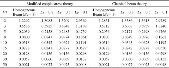
In order to investigate the size effect and the material distribution, the maximum dimensionless vertical displacements (at the free end of the beam) of edge cracked FGM nanobeam are presented
with different the material distribution (ER) and the dimensionless material length scale parameter
(h/l) for modified couple stress theory and classical beam theory for point load Q = 1000 μN, L/h = 20, ar = 0.8, b = h and the crack location ratio 𝜂 = 0.01 in Table 1.
As seen from Table 1, with the increase in the ratio of the ER, the displacements decrease, as
expected. This is because by increasing the ratio of the ER, the elasticity modulus of the beam and
Fig. 4 Deflections of the cantilever beam based on the modified coupled stress theory
Table 1 Maximum dimensionless of vertical displacements edge FGM nanobeam with different the material distribution (ER) and the dimensionless material length scale parameter (h/l) for point load Q = 1000
μN, L/h = 20, ar = 0.8, b = h and 𝜂 = 0.01
Modified couple stress theory Classical beam theory
h/l Homogeneous Beam (ER = 1) ER = 0.8 ER = 0.5 ER = 0.1 Homogeneous Beam (ER = 1) ER = 0.8 ER = 0.5 ER = 0.1 2 1.2292 1.3085 1.5209 2.9569 1.2851 1.3586 1.5613 2.9789 3 0.5586 0.5925 0.6848 1.3189 0.5712 0.6038 0.6939 1.3240 5 0.2039 0.2158 0.2485 0.4759 0.2056 0.2174 0.2498 0.4766 8 0.0800 0.0847 0.0974 0.1861 0.0803 0.0849 0.0976 0.1862 10 0.0513 0.0542 0.0624 0.1191 0.0514 0.0543 0.0625 0.1192 15 0.0228 0.0241 0.0277 0.0529 0.0228 0.0242 0.0278 0.0530 20 0.0128 0.0136 0.0156 0.0298 0.0129 0.0136 0.0156 0.0298 30 0.0057 0.0060 0.0069 0.0132 0.0057 0.0060 0.0069 0.0132 50 0.0021 0.0022 0.0025 0.0048 0.0021 0.0022 0.0025 0.0048 229
Şeref Doğuşcan Akbaş
the bending rigidity increase according to Eq. 1. As a result, the strength of the material increases. It can be noticed that the results predicted by the modified couple stress theory (MCST) are always smaller than those of the classical beam theory (CBT). Further, the difference between the two results is remarkable for thin nanobeams with h/l < 10. Also, it is seen from Table 1 that with the decrease in the ratio of the ER, the difference between the results of the modified couple stress
theory and classical beam theory decrease considerably. It shows that an increase in the material length scale parameter (h/l) leads to a decline on effects of size effect and difference between the results of MCST and CBT diminishes for h/l > 15.
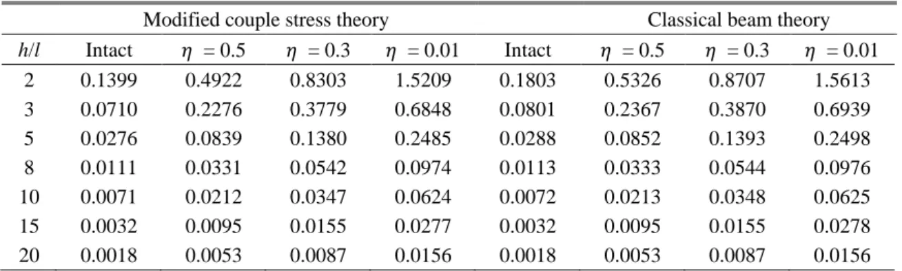
In Table 2, the maximum dimensionless vertical displacements of the edge cracked FGM
nanobeam are presented with different the crack depth ratios (𝑎𝑟) and the dimensionless material
length scale parameter (h/l) for modified couple stress theory and classical beam theory for point load Q = 5000 μN, L/h = 20, ER = 0.5, b = h and 𝜂 = 0.01.
It is seen from Table 2, with the increase in the crack depth, the displacements increase, as expected. This is because by increasing the crack depth ratio, the beam becomes flexible. With the decrease in the crack depth, the difference between the results of the modified couple stress theory and classical beam theory decrease considerably. It shows that an increase in the material length
Table 2 Maximum dimensionless of vertical displacements edge FGM nanobeam with different the crack depth ratios (𝑎𝑟) and the dimensionless material length scale parameter (h/l) for point load Q = 5000
μN, L/h = 20, ER = 0.5, b = h and 𝜂 = 0.01
Modified couple stress theory Classical beam theory
h/l Intact 𝑎𝑟= 0.1 𝑎𝑟= 0.5 𝑎𝑟= 0.8 Intact 𝑎𝑟= 0.1 𝑎𝑟= 0.5 𝑎𝑟= 0.8 2 0.1399 0.1461 0.2774 1.5209 0.1803 0.1865 0.3178 1.5613 3 0.0710 0.0728 0.1321 0.6848 0.0801 0.0819 0.1412 0.6939 5 0.0276 0.0282 0.0496 0.2485 0.0288 0.0295 0.0508 0.2498 8 0.0111 0.0113 0.0197 0.0974 0.0113 0.0115 0.0199 0.0976 10 0.0071 0.0073 0.0126 0.0624 0.0072 0.0074 0.0127 0.0625 15 0.0032 0.0033 0.0056 0.0277 0.0032 0.0033 0.0056 0.0278 20 0.0018 0.0018 0.0032 0.0156 0.0018 0.0018 0.0032 0.0156
Table 3 Maximum dimensionless of vertical displacements edge FGM nanobeam with different the crack locations (𝜂) and the dimensionless material length scale parameter (h/l) for point load Q = 5000 μN,
L/h = 20, ER = 0.5, b = h and ar = 0.8
Modified couple stress theory Classical beam theory
h/l Intact 𝜂 = 0.5 𝜂 = 0.3 𝜂 = 0.01 Intact 𝜂 = 0.5 𝜂 = 0.3 𝜂 = 0.01 2 0.1399 0.4922 0.8303 1.5209 0.1803 0.5326 0.8707 1.5613 3 0.0710 0.2276 0.3779 0.6848 0.0801 0.2367 0.3870 0.6939 5 0.0276 0.0839 0.1380 0.2485 0.0288 0.0852 0.1393 0.2498 8 0.0111 0.0331 0.0542 0.0974 0.0113 0.0333 0.0544 0.0976 10 0.0071 0.0212 0.0347 0.0624 0.0072 0.0213 0.0348 0.0625 15 0.0032 0.0095 0.0155 0.0277 0.0032 0.0095 0.0155 0.0278 20 0.0018 0.0053 0.0087 0.0156 0.0018 0.0053 0.0087 0.0156 230
Bending of a cracked functionally graded nanobeam
scale parameter (h/l) leads to a decline on effects of cracks in difference between the results of MCST and CBT.
In Table 3, the maximum dimensionless vertical displacements of edge cracked FGM nanobeam are presented with different the crack locations (𝜂) and the dimensionless material length scale parameter (h/l) for modified couple stress theory and classical beam theory for Q = 5000 μN, L/h = 20, ER = 0.5, b = h and ar = 0.8.
It is seen from Table 3 that when the crack locations get closer to the left end of the beam, the displacements increase for cantilever beam. This is because the crack at the left end of the beam has a most severe effect in the cantilever beam. As stated before, the material parameter has a very important role on the static behavior of the edge cracked FGM nanobeams, and it should be considered in the static and dynamic analysis of nanobeams. Also, it is believed that the tabulated results will be a reference with which other researchers can compare their results.
Also it is seen from Table 3 that increase in the material length scale parameter (h/l), the difference between results of the MCST and CBT decrease considerably for different ratio of the crack locations (𝜂). It is observed from tables that for the higher ratio of h/l, the classical cracked- beam theory can be used for the cracked problems of the nanoobeams.
In order to investigate the effect of crack depth ratio (𝑎𝑟) on the results of MCST and CBT, the
maximum dimensionless vertical displacements of edge cracked FGM nanobeam are presented
with different crack depth ratio in both MCST and CBT for Q = 1000 μN, L/h = 20, ER = 0.1, h/l =
3, b = h and 𝜂 = 0.01 in Fig. 5.
As seen from Fig. 5 that with increase in the crack depth ratios (𝑎𝑟), the difference between results of the MCST and CBT increases. In small values of the crack depth ratios, the difference between results of the MCST and CBT decrease considerably. It is observed from Fig. 5 that for small values of the crack depth ratios, the classical cracked-beam theory can be used for the cracked problems of the nanobeams.
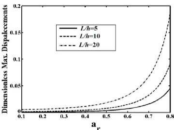
In Fig. 6, the maximum dimensionless vertical displacements of the edge cracked FGM
nanobeam are presented with different the crack depth ratios (𝑎𝑟) and the slenderness ratios (L/h)
Fig. 5 Maximum dimensionless vertical displacements of edge cracked FGM nanobeam with different the crack depth ratios (𝑎𝑟) in both MCST and CBT for Q = 1000 μN, L/h = 20, ER = 0.1, h/l = 3,
b=h and 𝜂 = 0.01
Şeref Doğuşcan Akbaş
Fig. 6 Maximum dimensionless vertical displacements of edge cracked FGM nanobeam with different the crack depth ratios (𝑎𝑟) and the slenderness ratios (L/h) for Q = 1000 μN, h/l = 8, ER = 0.1, b = h and 𝜂 = 0.01
on modified couple stress theory for Q = 1000 μN, h/l = 8, ER = 0.1, b = h and 𝜂 = 0.01.
It is seen from Fig. 6 that with increase in the ratio of L/h, the difference among the crack depth ratios increase significantly. This is because by increasing the ratio of the L/h, the beam gets more flexible and makes more sensitive the cracks. It shows that the geometry properties have a very important role on the static behavior of the edge cracked nanobeams.
In Fig. 7, the effects the crack locations (𝜂) on the results of MCST and CBT are plotted for Q= 1000 μN, L/h = 20, ER = 0.1, h/l = 3, b = h and ar = 0.6.
Fig. 7 Maximum dimensionless vertical displacements of edge cracked FGM nanobeam with different the crack locations (𝜂) in both MCST and CBT for Q = 1000 μN, L/h = 20, ER = 0.1, h/l = 3, b =
h and 𝜂 = 0.01 232
Bending of a cracked functionally graded nanobeam
It is seen from Fig. 7 that with decrease in the crack locations (𝜂), in other words, when the crack locations get closer to the left end of the beam, the difference between results of the MCST and CBT increases considerably. This is because the crack at the left end of the beam has a most severe effect in the cantilever beam. Therefore, the beam gets more flexible and makes more sensitive the cracks. The reasons for large difference between MCST and CBT in small values of the crack locations is by using the classical cracked-beam theory for the cracked nanobeams based on the modified couple stress theory (MCST). It is observed from Fig. 7 that in high values of the crack locations, in other words, when the crack locations get closer to the free end of the beam, the difference between results of the MCST and CBT decreases because the effect of the crack on the beam is low when the crack gets closer to the free end.
In Fig. 8, the maximum dimensionless vertical displacements of the edge cracked FGM nanobeam are presented with different the crack locations (𝜂) and the slenderness ratios (L/h) on modified couple stress theory for Q = 1000 μN, h/l = 8, ER = 0.1, b = h and ar = 0.8.
It is seen from Fig. 8 that with increase in the ratio of L/h, the difference among the crack depth ratios increase significantly. It is mentioned before that, because by increasing the ratio of the L/h, the beam gets more flexible and makes more sensitive the cracks. Also it seen from Fig. 8 that, with increase in the crack locations (𝜂), the difference among the results of the L/h decreases considerably as like the results of the Fig. 7.
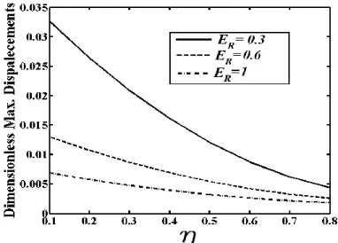
In order to investigate relationship between the effect of crack depth ratio (𝑎𝑟) and the material distribution, the maximum dimensionless vertical displacements (at the free end of the beam) of
edge cracked FGM nanobeam are presented with different ratio of ER and ar on modified couple
stress theory for Q = 1000 μN, L/h = 20, h/l = 8, b = h and 𝜂 = 0.01 in Fig. 9.
It is seen from Fig. 9 that increases in the Young’s modulus ratio ER causes decrease in the
displacements. When the Young’s modulus ratio ER increases, the elasticity modulus of the beam
increases according to Eq. (1). Another result of the Fig. 9 that with the increase in Young’s modulus ratio ER, the differences of the crack depth ratio ar decrease seriously. This is because, an
increase in the Young’s modulus ratio ER leads to an increase in the elasticity modulus and the
Fig. 8 Maximum dimensionless vertical displacements of edge cracked FGM nanobeam with different the crack locations (𝜂) and the slenderness ratios (L/h) for Q = 1000 μN, h/l = 8, ER = 0.1, b = h and ar = 0.8
Şeref Doğuşcan Akbaş
Fig. 9 Maximum dimensionless vertical displacements of edge cracked FGM nanobeam with different the crack depth ratios (𝑎𝑟) and the material distribution ratio (ER) for Q = 1000 μN, L/h = 20, h/l = 8, b = h and 𝜂 = 0.01
bending rigidity. As a result, the strength of the material increases. Hence, the beam becomes more strength and the effect of the crack on the FGM nanobeam decreases. It shows that with the suitable choice of ER, the negative effects of the crack can be reduced.
In Fig. 10, the maximum dimensionless vertical displacements of the edge cracked FGM nanobeam are presented with different the crack locations (𝜂) and the material distribution on
modified couple stress theory for Q = 1000 μN, L/h = 20, h/l = 8, b = h and ar = 0.8.
Fig 10 Maximum dimensionless vertical displacements of edge cracked FGM nanobeam with different the crack locations (𝜂) and the material distribution ratio (ER) for Q = 1000 μN, L/h = 20, h/l = 8, b = h and ar = 0.8
Bending of a cracked functionally graded nanobeam
It is observed from Fig. 10 that with the increase in Young’s modulus ratio ER, the differences
of the crack locations decrease seriously. It is observed from results that the distribution of the material plays an important role on the mechanical behaviour of the FGM nanobeam. It shows that FGM is very effective for reducing the negative influence of the cracks. Also, it is observed from Fig. 10 that in high values of the crack locations, in other words, when the crack locations get
closer to the free end of the beam, the difference between results of the ratio ER decreases because
the effects of the crack on the beam diminish when the crack gets closer to the free end.
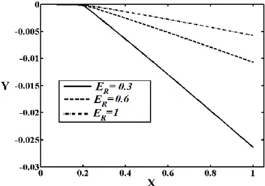
Figs. 11, 12 and 13 display the effect of the material distribution, the crack depth and the crack location on the deflected shape of the beams for Q = 1000 μN, L/h = 20, h/l = 8, b = h.
It is observed from Fig. 11 that with the increase in the ratio of the ER, the displacements
Fig. 11 The effect of the material distribution ratio (ER) on the deflected shape of the FGM nanobeam for Q = 1000 μN, L/h = 20, h/l = 8, b = h 𝜂 = 0.2 and ar = 0.8
Fig. 12 The effect of the crack depth ratios (𝑎𝑟) on the deflected shape of the FGM nanobeam for Q = 1000 μN, L/h = 20, h/l = 8, b = h, 𝜂 = 0.2 and ER = 0.1.
Şeref Doğuşcan Akbaş
Fig. 13 The effect of the crack locations (𝜂) on the deflected shape of the FGM nanobeam for Q = 1000
μN, L/h = 20, h/l = 8, b = h, ar = 0.8 and ER = 0.1
decrease, as expected. It is stated before that because of increasing the ratio of the ER, the elasticity
modulus of the beam and the bending rigidity increase according to Eq. (1). As a result, the strength of the material increases. Clearly, by having a suitable material distribution of the FGM,
the negative effect of the crack can be reduced. Evidently, Young’s modulus ratio ER plays a very
important role in the mechanical response of the FGM nanobeam.
From Fig. 12, it is seen that with the increase in the crack depth ratio, the displacement increases, as expected. This is due to the fact that increasing the crack depth ratio results in the increase of the flexibility of the FGM nanobeam. The results indicate that the cracks are very s e n s i t i v e t o t h e c h a n g e i n t h e m e c h a n i c a l b e h a v i o u r o f t h e F G M n a n o b e a m. It is clearly seen from Fig. 13 that when the crack location gets closer to the left end (fixed end), the displacement of the FGM nanobeam increases, due to the fact that the crack at the fixed end has a most severe effect on the beam. So, when the crack location gets closer to the fixed end, the beam gets more flexible. It was mentioned previously that as the crack gets closer to the left end, the strength of the beam decreases. As can be seen, the crack location plays an important role in the static response of the FGM nanobeams.
4. Conclusions
This paper examines static bending of an edge cracked FGM cantilever nanobeam subjected to transversal point load at the free end based on the modified couple stress theory by using finite element method within the Euler-Bernoulli beam theory. Material properties of the beam change in the height direction according to exponential distributions. The cracked beam is modelled using a proper modification of the classical cracked-beam theory consisting of two sub-beams connected through a massless elastic rotational spring. The elastic deflections of the edge cracked nano beams are calculated and discussed for different crack positions, different lengths of the beam, different length scale parameter, different crack depths, and different material distributions. In order to establish the accuracy of the present formulation and results, the deflections are obtained,
Bending of a cracked functionally graded nanobeam
and compared with the published results available in the literature. Good agreement is observed. The primary purpose of this study is to fill this gap for FGM nanobeams.
The following conclusions are reached from the obtained results:
(1) With the suitable choice of material distribution, the negative effects of the crack can be
reduced.
(2) FGM is very effective for reducing the negative influence of the cracks.
(3) The crack location and the crack depth play an important role in the static response of the
FGM nanobeams.
(4) It is found that the deflections of the FGM nanobeam by the classical beam theory are always larger than those by the modified couple stress theory.
(5) The geometry properties and material parameter have a very important role on the static
behavior of the edge cracked FGM nanobeams.
(6) With increase in the material length scale parameter (h/l), the difference between results
of the MCST and CBT decrease considerably for different ratio of the crack locations (𝜂) and the crack depth ratio(𝑎𝑟).
(7) With increase in the ratio of h/l, the effects of the cracks on the static responses of the nano beams are decrease significantly. With increase in the ratio of h/l, the difference among the crack depth ratios diminishes. After a certain value of the ratio of h/l and L/h, the classical cracked-beam model can be used for the cracked problems of the nanobeams.
(8) With increase in the crack locations (𝜂), the difference among the results of the L/h decreases considerably.
(9) Young’s modulus ratio ER plays a very important role in the mechanical response of the
FGM nanobeam.
(10) For the smaller ratio of L/h, the modified couple stress theory must be used instead of the classical beam theory.
(11) It is believed that the tabulated results will be a reference with which other researchers can compare their results.
References
Aissani, K., Bouiadjra, M.B., Ahouel, M. and Tounsi, A. (2015), “A new nonlocal hyperbolic shear deformation theory for nanobeams embedded in an elastic medium”, Struct. Eng. Mech., Int. J., 55(4), 743-763.
Akbaş, Ş.D. (2016a), “Analytical solutions for static bending of edge cracked micro beams”, Struct. Eng.
Mech., Int. J., 59(3), 579-599.
Akbaş, Ş.D. (2016b), “Forced Vibration Analysis of Viscoelastic Nanobeams Embedded in an Elastic Medium”, Smart Struct. Syst., Int. J., 18(6), 1125-1143.
Akbaş, Ş.D. (2016c), “Static Analysis of a Nano Plate by using Generalized Differantial Quadrature Method”, Int. J. Eng. Appl. Sci., 8(2), (Special Issue: Nanomechanics), 30-39.
Akbaş, Ş.D. (2017a), “Forced vibration analysis of functionally graded nanobeams”, Int. J. Appl. Mech., 9(7), 1750100.
Akbaş, Ş.D. (2017b), “Free vibration of edge cracked functionally graded microscale beams based on the modified couple stress theory”, Int. J. Struct. Stabil. Dyn., 17(3), 1750033.
DOI: http://dx.doi.org/10.1142/S021945541750033X
Şeref Doğuşcan Akbaş
Akbaş, Ş.D. (2018), “Forced vibration analysis of cracked functionally graded microbeams”, Adv. Nano Res.,
Int. J., 6(1), 39-55.
Akgöz, B. and Civalek, Ö . (2012), “Analysis of microtubules based on strain gradient elasticity and modified couple stress theories”, Adv. Vib. Eng., 11(4), 385-400.
Akgöz, B. and Civalek, Ö . (2013), “Buckling analysis of linearly tapered micro-Columns based on strain gradient elasticity”, Struct. Eng. Mech., Int. J., 48(2), 195-205.
Akgöz, B. and Civalek, Ö . (2014), “Thermo-mechanical buckling behavior of functionally graded microbeams embedded in elastic medium”, Int. J. Eng. Sci., 85, 90-104.
Akgöz, B. and Civalek, Ö . (2015a), “Bending analysis of FG microbeams resting on Winkler elastic foundation via strain gradient elasticity”, Compos. Struct., 134, 294-301.
Akgöz, B. and Civalek, Ö . (2015b), “A novel microstructure-dependent shear deformable beam model”, Int.
J. Mech. Sci., 99, 10-20.
Akgöz, B. and Civalek, Ö . (2016), “Bending analysis of embedded carbon nanotubes resting on an elastic foundation using strain gradient theory”, Acta Astronautica, 119, 1-12.
Ansari, R., Gholami, R. and Sahmani, S. (2011), “Free vibration analysis of size-dependent functionally graded microbeams based on the strain gradient Timoshenko beam theory”, Compos. Struct., 94(1), 2011, 221-228.
Ansari, R., Gholami, R. and Darabi, M.A. (2012), “A nonlinear Timoshenko beam formulation based on strain gradient theory”, J. Mech. Mater. Struct., 7(2), 95-211.
Ansari, R., Gholami, R., Faghih Shojaei, M., Mohammadi, V. and Sahmani, S. (2013a), “Size-dependent bending, buckling and free vibration of functionally graded Timoshenko microbeams based on the most general strain gradient theory”, Compos. Struct., 100, 385-397.
Ansari, R., Gholami, R. and Sahmani, S. (2013b), “Size-dependent vibration of functionally graded curved microbeams based on the modified strain gradient elasticity theory”, Arch. Appl. Mech., 83(10), 1439-1449.
Ansari, R., Faghih Shojaei, M., Gholami, R., Mohammadi, V. and Darabi, M.A. (2013c), “Thermal postbuckling behavior of size-dependent functionally graded Timoshenko microbeams”, Int. J.
Non-Linear Mech., 50, 127-135.
Ansari, R., Gholami, R., Faghih Shojaei, M., Mohammadi, V. and Sahmani, S. (2013d), “Buckling of FGM Timoshenko microbeams under in-plane thermal loading based on the modified strain gradient theory”,
Int. J. Multiscale Computat. Eng., 11(4), 389-405.
Ansari, R., Faghih Shojaei, M., Mohammadi, V., Gholami, R. and Rouhi, H. (2014a), “Nonlinear vibration analysis of microscale functionally graded Timoshenko beams using the most general form of strain gradient elasticity”, J. Mech., 30(2), 161-172.
Ansari, R., Gholami, R. and Sahmani, S. (2014b), “Free vibration of size-dependent functionally graded microbeams based on the strain gradient Reddy beam theory”, Int. J. Computat. Methods Eng. Sci. Mech., 15(5), 401-412.
Ansari, R., Ashrafi, M.A. and Arjangpay, A. (2015), “An exact solution for vibrations of postbuckled microscale beams based on the modified couple stress theory”, Appl. Math. Model., 39(10-11), 3050-3062. Asghari, M., Ahmadian, M.T., Kahrobaiyan, M.H. and Rahaeifard, M. (2010), “On the size dependent
behavior of functionally graded micro-beams”, Mater. Des., 31(5), 2324-3249.
Berrabah, H.M., Tounsi, A., Semmah, A. and Adda, B. (2013), “Comparison of various refined nonlocal beam theories for bending, vibration and buckling analysis of nanobeams”, Struct. Eng. Mech., Int.
J., 48(3), 351-365.
Broek, D. (1986), Elementary Engineering Fracture Mechanics, Martinus Nijhoff Publishers, Dordrecht, Netherlands.
Dai, H.L., Wang, Y.K. and Wang, L. (2015), “Nonlinear dynamics of cantilevered microbeams based on modified couple stress theory”, Int. J. Eng. Sci., 94,103-112.
Daneshmehr, A.R., Abadi, M.M. and Rajabpoor, A. (2013), “Thermal effect on static bending, vibration and buckling of reddy beam based on modified couple stress theory”, Appl. Mech. Mater., 332, 331-338. Darijani, H. and Mohammadabadi, H. (2014), “A new deformation beam theory for static and dynamic 238
Bending of a cracked functionally graded nanobeam
analysis of microbeams”, Int. J. Mech. Sci., 89, 31-39.
Ebrahimi, F. and Barati, M.R. (2016a), “An exact solution for buckling analysis of embedded piezoelectro-magnetically actuated nanoscale beams”, Adv. Nano Res., Int. J., 4(2), 65-84.
Ebrahimi, F. and Barati, M.R. (2016b), “Analytical solution for nonlocal buckling characteristics of higher-order inhomogeneous nanosize beams embedded in elastic medium”, Adv. Nano Res., Int. J., 4(3), 229-249.
Ehyaei, J., Ebrahimi, F. and Salari, E. (2016), “Nonlocal vibration analysis of FG nano beams with different boundary conditions”, Adv. Nano Res., Int. J., 4(2), 85-111.
Eltaher, M.A., Khater, M.E., Park, S., Abdel-Rahman, E. and Yavuz, M. (2016), “On the static stability of nonlocal nanobeams using higher-order beam theories”, Adv. Nano Res., Int. J., 4(1), 51-64.
Erdogan, F. and Wu, B.H. (1997), “The Surface Crack Problem for a Plate with Functionally Graded Properties”, J. Appl. Mech., 64(3), 448-456.
Eringen, A.C. (1972), “Nonlocal polar elastic continua”, Int. J. Eng. Sci., 10(1), 1-16.
Fang, T.-H. and Chang, W.-J. (2003), “Sensitivity analysis of scanning near-field optical microscope probe”,
Optics Laser Technol., 35(4), 267-271.
Fang, T.-H., Chang, W.-J. and Liao, S.-C. (2003), “Simulated nanojet ejection process by spreading droplets on a solid surface”, J. Phys.: Condensed Matter, 15(49), 8263-8271.
Farokhi, H. and Ghayesh, M.H. (2015), “Thermo-mechanical dynamics of perfect and imperfect Timoshenko microbeams”, Int. J. Eng. Sci., 91, 12-33.
Fleck, N.A. and Hutchinson, J.W. (1993), “A phenomenological theory for strain gradient effects in plasticity”, J. Mech. Phys. Solids, 41(12), 1825-1857.
Fu, Y., Du, H. and Zhang, S. (2003), “Functionally graded TiN/TiNi shape memory alloy films”, Mater.
Lett., 57(20), 2995-2999.
Ghayesh, M.H., Amabili, M. and Farokhi, H. (2013), “Three-dimensional nonlinear size-dependent behaviour of Timoshenko microbeams”, Int. J. Eng. Sci., 71, 1-14.
Gürses, M., Akgöz, B. and Civalek, Ö . (2012), “Annular sector plates using the nonlocal continuum theory via eight-node discrete singular convolution transformation”, Appl. Math. Computat., 219(6), 3226-3240. Hasanyan, D.J., Batra, R.C. and Harutyunyan, S. (2008), “Pull-in instabilities in functionally graded
microthermoelectromechanical systems”, J. Therm. Stresses, 31(10), 1006-1021.
Hasheminejad, B.S.M., Gheshlaghi, B., Mirzaei, Y. and Abbasion, S. (2011), “Free transverse vibrations of cracked nanobeams with surface effects”, Thin. Solid Films, 519(8), 2477-2482.
Hosseini-Hashemi, S., Fakher, M., Nazemnezhad, R. and Sotoude Hag Highi, M.H. (2014), “Dynamic behavior of thin and thick cracked nanobeams incorporating surface effects”, Compos. Part B: Eng., 61, 66-72.
Hsu, J.C., Lee, H.L. and Chang, W.J. (2011), “Longitudinal vibration of cracked nanobeams using nonlocal elasticity theory”, Current Appl. Phys., 11(6), 1384-1388.
Kahrobaiyan, M.H., Asghari, M., Rahaeifard, M. and Ahmadian, M.T. (2010), “Investigation of the size dependent dynamic characteristics of atomic force microscope microcantilevers based on the modified couple stress theory”, Int. J. Eng. Sci., 48(12), 1985-1994.
Ke, L.-L., Wang, Y.-S. and Wang, Z.-D. (2011), “Thermal effect on free vibration and buckling of size-dependent microbeams”, Phys. E: Low-Dimensional Syst. Nanostruct., 43(7), 1387-1393.
Kocatürk, T. and Akbaş, Ş.D. (2013), “Wave propagation in a microbeam based on the modified couple stress theory”, Struct. Eng. Mech., Int. J., 46(3), 417-431.
Kong, S., Zhou, S., Nie, Z. and Wang, K. (2008), “The size-dependent natural frequency of Bernoulli–Euler micro-beams”, Int. J. Eng. Sci., 46(5), 427-437.
Kong, S.L. (2013), “Size effect on natural frequency of cantilever micro-beams based on a modified couple stress theory”, Adv. Mater. Res., 694-697, 221-224.
Lam, D.C.C., Yang, F., Chong, A.C.M., Wang, J. and Tong, P. (2003), “Experiments and theory in strain gradient elasticity”, J. Mech. Phys. Solids, 51(8), 1477-1508.
Liu, Y.P. and Reddy, J.N. (2011), “A nonlocal curved beam model based on a modified couple stress theory”, Int. J. Struct. Stabil. Dyn., 11(3), 495-512. DOI: 10.1142/S0219455411004233
Şeref Doğuşcan Akbaş
Liu, S.-J., Qi, S.-H. and Zhang, W.-M. (2013), “Vibration behavior of a cracked micro-cantilever beam under electrostatic excitation”, Zhendong yu Chongji/Journal of Vibration and Shock, 32(17), 41-45. Loya, J., López-Puente, J., Zaera, R. and Fernández-Sáez, J. (2009), “Free transverse vibrations of cracked
nanobeams using a nonlocal elasticity model”, J. Appl. Phys., 105(4), 044309.
Lü, C.F., Lim, C.W. and Chen, W.Q. (2009), “Size-dependent elastic behavior of FGM ultra-thin films based on generalized refined theory”, Int. J. Solids Struct., 46(5), 1176-1185.
Ma, H.M., Gao, X.L. and Reddy, J.N. (2008), “A microstructure-dependent Timoshenko beam model based on a modified couple stress theory”, J. Mech. Phys. Solids, 56(12), 3379-3391.
Mindlin, R.D. (1963), “Influence of couple-stresses on stress concentrations”, Exp. Mech., 3, 1-7.
Mindlin, R.D. and Tiersten, H.F. (1962), “Effects of couple-stresses in linear elasticity”, Arch. Ration Mech.
Anal., 11(1), 415-448.
Mohammadi-Alasti, B., Rezazadeh, G., Borgheei, A.M., Minaei, S. and Habibifar, R. (2011), “On the mechanical behavior of a functionally graded micro-beam subjected to a thermal moment and nonlinear electrostatic pressure”, Compos. Struct., 93(6), 1516-1525.
Nateghi A. and Salamat-Talab, M. (2013), “Thermal effect on size dependent behavior of functionally graded microbeams based on modified couple stress theory”, Compos. Struct., 96, 97-110.
Park, S.K. and Gao, X.L. (2006), “Bernoulli–Euler beam model based on a modified couple stress theory”, J.
Micromech. Microeng., 16(11), 2355-2359.
Pei, J., Tian, F. and Thundat, T. (2004), “Glucose biosensor based on the microcantilever”, Anal. Chem., 76(2), 292-297.
Rahaeifard, M., Kahrobaiyan, M.H. and Ahmadian, M.T. (2009), “Sensitivity analysis of atomic force microscope cantilever made of functionally graded materials”, Proceedings of the 3rd International
Conference on Micro- and Nanosystems, San Diego, CA, USA.
Reddy, J.N. (2011), “Microstructure-dependent couple stress theories of functionally graded beams”, J.
Mech. Phys. Solids, 59(11), 2382-2399.
Rezazadeh, G., Tahmasebi, A. and Zubtsov, M. (2006), “Application of piezoelectric layers in electrostatic MEM actuators: controlling of pull-in voltage”, J. Microsyst. Technol., 12(12), 1163-1170.
Salamat-Talab, M., Nateghi, A. and Torabi, J. (2012), “Static and dynamic analysis of third-order shear deformation FG micro beam based on modified couple stress theory”, Int. J. Mech. Sci., 57(1), 63-73. Sedighi, H.M., Changizian, M. and Noghrehabadi, A. (2014), “Dynamic pull-in instability of geometrically
nonlinear actuated micro-beams based on the modified couple stress theory”, Latin Am. J. Solids Struct., 11(5), 810-825.
Senturia, S.D. (1998), “CAD challenges for microsensors, microactuators, and microsystems”, Proceeding
of IEEE, 86(8), 1611-1626.
Shaat, M., Akbarzadeh Khorshidi, M., Abdelkefi, A. and Shariati, M. (2016), “Modeling and vibration characteristics of cracked nano-beams made of nanocrystalline materials”, Int. J. Mech. Sci., 115-116, 574-585.
Şimsek, M. (2010), “Dynamic analysis of an embedded microbeam carrying a moving microparticle based on the modified couple stress theory”, Int. J. Eng. Sci., 48(12), 1721-1732.
Şimşek, M. and Reddy, J.N. (2013a), “Bending and vibration of functionally graded microbeams using a new higher order beam theory and the modified couple stress theory”, Int. J. Eng. Sci., 64, 37-53.
Şimşek, M. and Reddy, J.N. (2013b), “A unified higher order beam theory for buckling of a functionally graded microbeam embedded in elastic medium using modified couple stress theory”, Compos. Struct., 101, 47-58.
Şimşek, M., Kocatürk, T. and Akbaş, Ş.D. (2013), “Static bending of a functionally graded microscale Timoshenko beam based on the modified couple stress theory”, Compos. Struct., 95, 740-747.
Tang, M., Ni, Q., Wang, L., Luo, Y. and Wang, Y. (2014), “Size-dependent vibration analysis of a microbeam in flow based on modified couple stress theory”, Int. J. Eng. Sci., 85, 20-30.
Tadi Beni, Y., Jafari, A. and Razavi, H. (2015), “Size Effect on Free Transverse Vibration of Cracked Nano-beams using Couple Stress Theory”, Int. J. Eng., 28(2), 296-304.
Tagrara, S.H., Benachour, A., Bouiadjra, M.B. and Tounsi, A. (2015), “On bending, buckling and vibration 240
Bending of a cracked functionally graded nanobeam
responses of functionally graded carbon nanotube-reinforced composite beams”, Steel Compos. Struct.,
Int. J., 19(5), 1259-1277.
Torabi, K. and Nafar Dastgerdi, J. (2012), “An analytical method for free vibration analysis of Timoshenko beam theory applied to cracked nanobeams using a nonlocal elasticity model”, Thin. Solid Films, 520(21), 6595-6602.
Toupin, R.A. (1962), “Elastic materials with couple stresses”, Arch. Ration Mech. Anal., 11(1), 385-414. Xia, W., Wang, L. and Yin, L. (2010), “Nonlinear non-classical microscale beams: static, bending,
postbuckling and free vibration”, Int. J. Eng. Sci., 48(12), 2044-2053.
Wang, L. (2010), “Size-dependent vibration characteristics of fluid-conveying Microtubes”, J. Fluids Struct., 26(4), 675-684.
Wang, L., Xu, Y.Y. and Ni, Q. (2013), “Size-dependent vibration analysis of three-dimensional cylindrical microbeams based on modified couple stress theory: A unified treatment”, Int. J. Eng. Sci., 68, 1-10. Wang, Y.-G., Lin, W.-H., Zhou, C.-L. and Liu, R.-X. (2014), “Thermal postbuckling and free vibration of
extensible microscale beams based on modified couple stress theory”, J. Mech., 31(1), 37-46.
Witvrouw, A. and Mehta, A. (2005), “The use of functionally graded Ploy-SiGe Layers for MEMS Applications”, Mater. Sci. Forum, 492-493, 255-260.
Yang, F., Chong, A.C.M., Lam, D.C.C. and Tong, P. (2002), “Couple stress based strain gradient theory for elasticity”, Int. J. Solids Struct., 39(10), 2731-2743.
Yu, Z. and Chu, F. (2009), “Identification of crack in functionally graded material beams using the p- version of finite element method”, J. Sound Vib., 325(1-2), 69-84.
Zamanzadeh, M., Rezazadeh, G., Jafarsadeghi-Poornaki, I. and Shabani, R. (2013), “Static and dynamic stability modeling of a capacitive FGM micro-beam in presence of temperature changes”, Appl. Math.
Model., 37(10-11), 6964-6978.
Zemri, A., Houari, M.S.A., Bousahla, A.A. and Tounsi, A. (2015), “A mechanical response of functionally graded nanoscale beam: an assessment of a refined nonlocal shear deformation theory beam theory”, Struct. Eng. Mech., Int. J., 54(4), 693-710.
Zhang, J. and Fu, Y. (2012), “Pull-in analysis of electrically actuated viscoelastic microbeams based on a modified couple stress theory”, Meccanica, 47(7), 1649-1658.
Zook, J.D., Burns, D.W., Guckel, H., Smegowsky, J.J., Englestad, R.L. and Feng, Z. (1992), “Characteristics of polysilicon resonant microbeams”, Sensors Actuat., 35(1), 31-59.
CC
Şeref Doğuşcan Akbaş
Appendix
The interpolation functions for axial degrees of freedom are
𝜑 𝑈 𝑋 = 𝜑1 𝑈 𝑋 𝜑2 𝑈 𝑋 𝑇, (A1) Where 𝜑1 𝑈 X = − 𝑋 𝐿e+ 1 , (A2) 𝜑2 𝑈 (X) = 𝑋 𝐿e (A3)
The interpolation functions for transverse degrees of freedom are
𝜑 𝑉 X = 𝜑1 𝑉 X 𝜑2 𝑉 X 𝜑3 𝑉 X 𝜑4 𝑉 X 𝑇, (A4) Where 𝜑1 𝑉 (X) = 1 −3𝑋 2 𝐿2e + 2𝑋3 𝐿e3 (A5) 𝜑2 𝑉 (X) = −𝑋 +2𝑋 2 𝐿e − 𝑋3 𝐿3e (A6) 𝜑3 𝑉 (X) = 3𝑋 2 𝐿2e − 2𝑋3 𝐿3e (A7) 𝜑4 𝑉 (X) = 𝑋 2 𝐿e − 2𝑋3 𝐿e3 (A8)
Where 𝐿e indicates the length of the finite beam element.