(IJACSA) International Journal of Advanced Computer Science and Applications, Vol. 9, No. 3, 2018
248 | P a g e www.ijacsa.thesai.org
A High Gain MIMO Antenna for Fixed Satellite and
Radar Applications
Ahsan Altaf
Electrical-Electronics Engineering Department,
Istanbul Medipol University, Istanbul, Turkey
Khalid Mahmood
Electrical Engineering DepartmentUniversity of Technology Nowshehra,
Pakistan
Mehre Munir, Saad Hassan Kiani
Electrical Engineering DepartmentIqra National University Peshawar,
Pakistan
Abstract—Patch antennas have emerged rapidly with
advancement of communication technology. For antenna design purposes, Finite difference time domain (FDTD) method is a commonly used. This paper focuses on the interaction among elements of MIMO antenna also known as mutual coupling using FDTD method. An M shape is introduced and with placement of isolating structure, round about 12dB of isolation is increased without degradation of performance parameters. The proposed antenna design can be used for radar and satellite services applications.
Keywords—Mutual coupling; isolating structure; multiple input multiple output; radar application; finite difference time domain
I. INTRODUCTION
Patch antennas have several advantages over non planar Antennas [1]. Due to their light weight, cost effectiveness and multiband properties [2], patch structures have been of central attention among antenna designers and researchers. Computational electro magnetics (CEM) methods have become mostly important with the rapid developments in technologies in fields such as electromagnetic compatibility, antenna analysis, target recognition and lightning strike simulation [3]. Electromagnetic phenomena are ruled by the Maxwell equations, which can be calculated in either the frequency or the time domain. The finite difference time domain (FDTD) technique is possibly the simplest, both conceptually and in terms of implementation, of the full-wave techniques used to solve complications in electromagnetics [4], [5]. It can exactly tackle a wide range of complications. The FDTD algorithm as first suggested by Kane Yee in 1966 employs second-order central differences. Basic FDTD unit cell is shown in Fig. 1.
Mutual coupling is very common unwanted phenomena degrading antenna performance by degrading its parameters. Different approaches have been made in order to improve isolation including electro-magnetic band gap (EBG), Defected ground structure (DGS), line resonators of different shapes, ground patterning [6]-[8]. In this paper, a high gain MIMO antenna has been designed and in order to enhance isolation among patch elements an M shape on ground plane is patterned. The antenna has been analyzed with the in-house prepared FDTD package. This paper is organized as follows:
Fig. 1. Basic FDTD unit cell.
Section I covers Introduction, Section II covers antenna design. Section III focuses on Results and Discussions and in the last Section IV, Conclusion is covered.
II. ANTENNA DESIGN
Before designing a patch antenna, a single patch element is designed. In substrate selection, Roggers 5880 with permittivity of 2.2 and thickness comprising of 0.796mm is selected. The cell dimension used in the FDTD simulation program is x = 0.4mm, y = 0.389mm, z = 0.265mm and ∆t = 0.6407ps. An 8-cell thick PML layer is used resulting in an overall computation domain of 69 × 80 × 18 cells.
The antenna is fed by a z−directed electric field Gaussian pulse, Es, of 50ps waist and maximum amplitude of 1 in the manner described in [2] with a source resistance, Rs of 50Ω to reduce the number of time steps needed for convergence. The length and width of the patch are calculated using equations given below:
√
Here εr is the relative constant with f0 functioning frequency and C is the rapidity of light in vacuum.
Where
√
(IJACSA) International Journal of Advanced Computer Science and Applications, Vol. 9, No. 3, 2018 249 | P a g e www.ijacsa.thesai.org And ( )
Fig. 2. Patch antenna simulated waveform of voltage with 50Ω Resistance.
Fig. 3. Patch antenna simulated waveform of current with 50Ω Resistance.
Fig. 2 and 3 shows patch antenna simulated wave form of voltage and current source respectively with 50ohms of resistance. The design parameters are given in Table I. The antenna is as stated above designed at fundamental frequency of 7.45GHz. The isolating structure is then imposed between patch antenna elements as shown in Fig. 4, in order to improve isolation as high level of isolation can degrade antenna performance making it un-useful for applications.
Fig. 4. MIMO antenna design with isolation element.
Fig. 5. M Shape structure for surface currents suppressions.
Among isolation techniques, EBG and DGS structures have been found very efficient by antenna designers. In our proposed M shape shown in Fig. 5, l is the overall width of the structure, while s is the overall length. w is the distance between the 2 arms. Input resistance is set to be 50 ohms. The decoupling section. The decoupling unit act as a LC circuit and the resonance frequency of such decoupling unit is dependent on the value of inductance and capacitance.
TABLE I. PATCH ANTENNA DIMENSIONS
Parameters Length of patch Width of Patch Height of Patch Substrate Height Values in mm 16 12 0.8 0.796
TABLE II. DIMENSIONSOFMSHAPEDSTRUCTURES
Parameters l s w
Value (mm) 40 10 0.8
Table II shows the dimensions of M shape isolating structure. The proposed structure is resonated at our desired frequencies and blacks the surface wave’s interference between resonating elements.
III. RESULTS AND DISSCUSSIONS
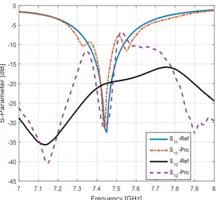
The S parameters show the performance of an antenna, as S11 is reflection co efficient and mutual coupling is taken in terms of S12. From Fig. 6, showing the S parameters, it is cleared that our isolating structure has increased 18dB of isolation.
(IJACSA) International Journal of Advanced Computer Science and Applications, Vol. 9, No. 3, 2018
250 | P a g e www.ijacsa.thesai.org
Fig. 6. S- Parameters plot of reference and proposed antenna.
The results between reference and proposed antenna have been summarized in Table III.
TABLE III. PERFORMANCE PARAMETERS OF ANTENNA ARRAY
Parameters Conventional Proposed
S11 -32dB -31.85dB S12 -18.00dB -31.0dB Gain 7.45dB 7.34dB VSWR 1.03 1.04 Bandwidth 290MHZ 270MHZ
Fig. 7. E field pattern of reference and proposed antenna.
Fig. 8. H field pattern of reference and proposed antenna.
Fig. 9. Current distribution path of reference antenna.
Fig. 10. Current distribution path of proposed antenna.
As seen from Fig. 7 and 8, the E and H plane of proposed and conventional antennas are nearly same showing our structure has not degrade antenna radiation patterns. Surface waves are undesirable in antenna arrays as the increase the back lobe radiation and antenna efficiency is decreased. Also with the increasing level of back lobe radiation SNR ration gets worse.
(IJACSA) International Journal of Advanced Computer Science and Applications, Vol. 9, No. 3, 2018
251 | P a g e www.ijacsa.thesai.org
By looking at Fig. 9 and 10, we can clearly indicate that with insertion of proposed structure, the radiating patch surface current is being blocked by isolating structure and is being prevented as compared to Fig. 9 in conventional MIMO antenna where surface current is directly interfering to passive patch and giving rise to coupling. From the above results, it is clear that our proposed isolating structure has resonated on our desired band frequency and has act as an LC circuit to stop unwanted coupling.
IV. CONCLUSION
This paper presents a simple approach of isolation enhancement using FDTD analysis. With insertion of proposed M shape structure, an enhancement of 12dB was increased and the performance parameters were not affected at all. With high gain of above 6.5dB, proposed antenna can be used for satellite services and radar applications.
REFERENCES
[1] Balanis, Constantine A. Antenna theory: analysis and design. John Wiley & Sons, 2016.
[2] Saad Hassan Kiani, Shahryar Shafique Qureshi, Khalid Mahmood,
Mehr-e- Munir and Sajid Nawaz Khan, “Tri-Band Fractal Patch Antenna for GSM and Satellite Communication Systems” International Journal of Advanced Computer Science and Applications(IJACSA), 7(10), 2016. [3] Ergul, Ozgur, et al. "Open problems in CEM: Error-controllable and
well-conditioned MoM solutions in computational electromagnetics: Ultimate surface integral-equation formulation." IEEE Antennas and Propagation Magazine 6.55 (2013): 310-331.
[4] Sullivan, Dennis M. Electromagnetic simulation using the FDTD method. John Wiley & Sons, 2013.
[5] Li, Hanyu, et al. "Massively parallel FDTD program JEMS-FDTD and its applications in platform coupling simulation." 2014 International Symposium on Electromagnetic Compatibility. IEEE, 2014.
[6] Sharawi, Mohammad S., Ahmed B. Numan, and Daniel N. Aloi. "Isolation improvement in a dual-band dual-element MIMO antenna system using capacitively loaded loops." Progress In Electromagnetics Research 134 (2013): 247-266.
[7] Ghosh, Jeet, et al. "Mutual Coupling Reduction Between Closely Placed Microstrip Patch Antenna Using Meander Line Resonator." Progress In Electromagnetics Research Letters 59 (2016): 115-122.
[8] Zhang, Y., Yu, T., Kong, L.Y., Lang, R.L. and Qin, H.L., 2016, May. Design of Fermat-Archimedes spiral dual-via EBG structure for low mutual coupling antenna array. In Electromagnetic Compatibility (APEMC), 2016 Asia-Pacific International Symposium on (Vol. 1, pp. 515-517).IEEE.