INNOVATIVE DESIGNS OF RF TRANSMIT
ARRAY COILS AND RF HEATING ANALYSIS OF
PATIENTS WITH IMPLANTED DBS
A DISSERTATION SUBMITTED TO
THE GRADUATE SCHOOL OF ENGINEERING AND SCIENCE OF BILKENT UNIVERSITY
IN PARTIAL FULFILLMENT OF THE REQUIREMENTS FOR THE DEGREE OF
DOCTOR OF PHILOSOPHY IN
ELECTRICAL AND ELECTRONICS ENGINEERING
By
Ehsan Kazemivalipour
September 2020
ii
INNOVATIVE DESIGNS OF RF TRANSMIT ARRAY COILS AND RF HEATING ANALYSIS OF PATIENTS WITH IMPLANTED DBS
By Ehsan Kazemivalipour September 2020
We certify that we have read this dissertation and that in our opinion it is fully adequate, in scope and in quality, as a dissertation for the degree of Doctor of Philosophy.
Ergin Atalar (Advisor)
Emine Ülkü Sarıtaş Çukur
Özgür Salih Ergül
Laleh Golestani Rad
Yiğitcan Eryaman
Approved for the Graduate School of Engineering and Science:
Ezhan Karaşan
iii
ABSTRACT
INNOVATIVE DESIGNS OF RF TRANSMIT ARRAY
COILS AND RF HEATING ANALYSIS OF PATIENTS
WITH IMPLANTED DBS
Ehsan Kazemivalipour
Ph.D. in Electrical and Electronics Engineering Advisor: Ergin Atalar
September 2020
A safe and efficient magnetic resonance imaging (MRI) test would rely on informed specification, design, implementation, assessment, and application of appropriately selected radiofrequency (RF) coils. Towards these goals, this dissertation comprises three contributions to novel RF transmit array (TxArray) coil design techniques and two contributions to RF heating reduction of deep brain stimulation (DBS) implants in RF transmit coils.
TxArray coils with multiple transmit elements provide the additional degrees of freedom that can be used to enhance field uniformity, accelerate acquisition time, enable RF shimming while intending to mitigate specific absorption rate (SAR) hotspots, and increase power efficiency. How a TxArray coil is designed can have a significant impact on its gain from parallel transmission technology. Thus, the first contribution of this dissertation is on the eigenmode analysis of the scattering matrix for the design of TxArray coils to obtain their efficient operation modes and achieve an efficient RF shimming in terms of power consumption. The algorithm is tested for the design of four 3T TxArray coils with 8 to 32 channels, and it is shown that it can enlarge the dimension of the excitation space by up to 50% compared with the commonly used design techniques. The next contribution is to establish a fast fine-tuning procedure to precisely design an imperfectly manufactured TxArray coil using its corresponding equivalent circuit model. By fitting the measured scattering parameters to a lumped circuit model, all inductances/resistances of an 8-channel 3T TxArray coil are estimated. The manufactured coil is then appropriately tuned only in a single iteration. As another contribution, a theoretical coil size optimization is
iv
introduced to minimize the magnetic coupling between non-adjacent transmit channels of a TxArray coil. By calculating all self/mutual-inductances of a 12-channel 3T TxArray coil and minimizing mutual-inductances, its sizes are determined. The finite element simulations are performed to demonstrate the feasibility of this approach.
One of the safety considerations of RF transmit coils is the localized SAR
amplification due to the interaction of metallic implants with the coil's electric fields. Therefore, the fourth contribution is on evaluating SAR mitigation performance at tips of patient-derived realistic DBS implants using a 3T patient-adjustable transmit coil, which uses a mechanically rotating linearly polarized birdcage resonator. The reconfigurable coil system decreases the SAR on average by 83% for unilateral leads and by 59% for bilateral leads in comparison to a conventional quadrature birdcage coil. In the final study, the local SAR amplification surrounding the tips of a large cohort of DBS implants with realistic lead trajectories in a commercially available vertical open-bore 1.2T coil and a standard horizontal closed-bore 1.5T birdcage coil is presented. On average, SAR is decreased by 31-fold in the 1.2T vertical coil compared to the 1.5T horizontal coil.
Overall, this dissertation proposes innovative approaches for designing TxArray coils and heating assessment and SAR reduction of DBS patients, which mainly contribute to improving the performance of RF transmit coils in terms of power efficiency and patient safety.
Keywords: Magnetic resonance imaging (MRI), Radiofrequency (RF) coil, Transmit array coil, Eigenmode analysis, Equivalent circuit model, Coupling, MRI safety, Deep brain stimulation (DBS), Specific absorption rate (SAR)
v
ÖZET
RF VERİCİ DİZİSİ SARGILARININ YENİLİKÇİ
TASARIMLARI VE İMPLANTE EDİLMİŞ DBS'Lİ
HASTALARIN RF ISINMA ANALİZİ
Ehsan Kazemivalipour
Elektrik ve Elektronik Mühendisliği, Doktora Tez Danışmanı: Ergin Atalar
Eylül 2020
Güvenilir ve verimli bir manyetik rezonans görüntüleme (MRG) testi, uygun şekilde seçilmiş RF sargıların tanımlama, tasarım, değerlendirme ve uygulanmasına dayanmaktadır. Bu amaçlar doğrultusunda, bu tez savunması özgün RF verici dizisi (TxArray) sargı tasarım tekniklerine üç katkıdan ve RF verici sargılarındaki derin beyin stimülasyonu (DBS) implantlarının RF ısınma azaltımına iki katkıdan oluşmaktadır.
Çoklu verici elementlerinden oluşan TxArray sargıları, alan tekdüzeliğini arttırabilmek, toplama süresini hızlandırabilmek, özgül soğurma oranı (ÖSO) noktalarını azaltmak amacıyla RF şim ayarlamasını mümkün kılabilmek ve güç verimliliğini arttırabilmek için ek serbestlik dereceleri sağlar. Bir TxArray sargısının nasıl tasarlandığı, paralel iletim teknolojisinden edinilen kazanç üzerinde önemli bir etkiye sahiptir. Böylece, bu tezin ilk katkısı, TxArray sargılarının tasarımı için verimli çalışma modlarını elde etmek ve güç tüketimi açısından verimli bir RF şimlemesi elde etmek amacıyla saçılma matrisinin özmod analizi üzerinedir. Algoritma, 8-32 kanallı dört 3T TxArray sargılarının tasarımı için test edilmiş ve yaygın olarak kullanılan tasarım tekniklerine kıyasla yayılma alanının boyutunu %50'ye kadar genişletebildiği gösterilmektedir. Bir sonraki katkı, karşılık gelen eşdeğer devre modelini kullanarak kusurlu bir şekilde üretilmiş bir TxArray sargısını tam olarak tasarlamak için hızlı bir ince ayar prosedürü oluşturmaktır. Ölçülen saçılma parametreleri bir toplu devre modeline uydurularak, 8 kanallı bir 3T TxArray sargısının tüm endüktans/dirençleri tahmin edilir. Üretilen sargı daha sonra yalnız tek bir iterasyonda uygun bir şekilde ayarlanır. Diğer bir katkı olarak, bir TxArray sargısının bitişik olmayan verici kanalları
vi
arasındaki manyetik kuplajı en aza indirmek için teorik bir sargı boyutu optimizasyonu öne sürülmüştür. 12 kanallı bir 3T TxArray sargısının tüm öz/karşılıklı endüktansları hesaplanarak ve karşılıklı endüktansları en aza indirgenerek boyutları belirlenir. Bu yaklaşımın uygulanabilirliğini göstermek amacıyla sonlu eleman simülasyonları gerçekleştirilir.
RF verici sargılarının güvenlik hususlarından biri, metalik implantların sargının elektrik alanları ile etkileşimi nedeniyle lokalize ÖSO amplifikasyonudur. Bu nedenle dördüncü katkı, mekanik olarak dönen doğrusal polarize bir kuş kafesi rezonatörü kullanan 3T ayarlanabilir verici bobini kullanılarak hastadan türetilen gerçekçi DBS implantlarının uçlarındaki ÖSO azaltma performansının değerlendirilmesi üzerinedir. Yeniden yapılandırılabilir sargı sistemi, ÖSO'ı geleneksel kuadratür kuş kafesi sargısına kıyasla, tek taraflı uçlar için ortalama %83 ve iki taraflı uçlar için %59 azaltmıştır. Son çalışmada, ticari olarak temin edilebilen dikey açık 1.2T sargısındaki ve standart yatay kapalı 1.5T kuş kafesi sargısındaki gerçekçi uç yörüngelerine sahip büyük bir DBS implant kohortunun uçları çevresindeki yerel ÖSO amplifikasyonu sunulur. Ortalama olarak ÖSO, 1.5T yatay sargıya kıyasla 1.2T dikey sargıda 31 kat azalmıştır.
Genel olarak, bu tez, esasen RF verici sargılarının güç verimliliği ve hasta güvenliği açısından performansını iyileştiren, TxArray sargılarının tasarımı, ısınma değerlendirmesi ve DBS hastalarının ÖSO azaltımı için yenilikçi yaklaşımlar öne sürmektedir.
Anahtar sözcükler: Manyetik rezonans görüntüleme (MRG), Radyo-frekansı (RF)
sargı, Verici dizisi sargısı, Özmod analiz, Eşdeğer devre modeli, Kuplaj, MRG güvenliği, Derin beyin stimülasyonu (DBS), Özgül soğurma oranı (ÖSO)
vii
Acknowledgment
Doing the Ph.D. is like going through a challenging journey, which without many people's support and contribution it was not possible to come to the endpoint of this journey. I would express my deep gratitude to all the people who helped and supported me during this journey to make this experience unforgettable and this dissertation possible.
First and foremost, I would like to extend my sincere gratefulness to Prof. Ergin Atalar for his continued guidance, infinite support, encouragement, and patience throughout my Ph.D. studies. His immense knowledge and unwavering enthusiasm for research kept me engaged with my studies and research. His generous support and help let me pursue my research freely and taught me how to be a researcher, not just a student. I would like to thank him for providing such a great, professional, and friendly research environment at UMRAM.
My appreciation also extends to Prof. Laleh Golestani Rad for her incredible contribution, support, help, and advice whenever I need. Her support and guidance resulted in shaping two chapters of my dissertation. She generously shared their collected data and some tools at Northwestern University with me, which they played an essential role in my research.
I also convey my grateful thanks to my thesis committee members, Prof. Emine Ülkü Sarıtaş, Prof. Özgür Salih Ergül, Prof. Laleh Golestani Rad, and Prof. Yiğitcan Eryaman for their insightful comments, valuable suggestions, and inquiries and their precious time and effort assessing this dissertation.
I would state my special thanks to my colleagues at UMRAM and Northwestern University, which without their contribution and help on this research it would be hard to be at this point: Dr. Alireza Sadeghi-Tarakameh, Uğur Yılmaz, Umut Gundogdu, Dr. Bhumi Bhusal, Jasmine Vu, and Dr. Bach Thanh Nguyen.
I would express my thanks to all the UMRAM family and my lab mates for providing such a friendly and professional environment. My special thanks go to Prof. Kader Karlı Oğuz, Dr. Erkan Dorken, Aydan Ercingoz, Elif Ünal, Dr. Volkan Acıkel,
viii
Dr. Cemre Arıyurek, Maryam Salim, Reza Babaloo, Suheyl Taraghinia, Mina Elhami, Dr. Manouchehr Takrimi, Taner Demir, Berk Silemek, Dr. Koray Ertan, Reyhan Ergün, Bilal Tasdelen, Said Aldemir, Mustafa Can Delikanlı, Ahmet Fatih Yaprak, Ziba Arghiani, Mert Bozkurt and my dear friends, Bahram, Mehdi, Elnaz, Sina, Maryam, Mohammadali, Gamze, Amir, Zeynab, Wiria, Fatemeh, Parviz, Aysan, Yashar, Leila, Khalil, Dariush, Meysam, and many others I did not write here, but they all touched my heart.
My deepest gratitude, love, and appreciation goes to my dear parents, grandmothers, mother and father in law, my sisters Zahra and Rezvan, and my old dear friend and sister in law, Ladan, for their everlasting support, continuous encouragement, and love. Without their blessings, I would not have this accomplishment.
Finally and above all, I wish to acknowledge the support and great love of my dear wife and my best friend, Laleh, who always support me, uplift me, comfort me, and bring joy to my soul as she shares a piece of her own in the precise magical moment it needed to happen. I feel very lucky to be able to experience life alongside her.
ix
Content
1 Introduction .. . . 1
2 Eigenmode Analysis of the Scattering Matrix for the Design of MRI Transmit Array Coils. . . 6
2.1 Preface. . . 6
2.2 Introduction. . . 6
2.3 Theory. . . 8
2.4 Methods. . . 10
2.4.1 -opt design strategy . . . 10
2.4.2 Proposed model for RF TxArray coil . . . 12
2.4.3 Numerical simulations. . . 13
2.4.4 Measurements . . . 15
2.5 Results. . . 17
2.5.1 Simulation results. . . 17
2.5.2 Measurement results. . . 25
2.6 Discussion and conclusion. . . 26
3 A Fast Fine-tuning Method for Designing an Imperfectly Manufactured Transmit Array Coil using its Equivalent Circuit Model. . . 30
3.1 Preface. . . 30
3.2 Introduction. . . 30
3.3 Theory and methods. . . 32
3.3.1 Simulated TxArray coil . . . 32
3.3.2 Manufactured TxArray coil. . . 34 3.4 Results. . . 38
x
4 Optimized Transmit Array Coil for Minimum Coupling: A Simulation
Study on a Degenerate Birdcage Transmit Array Coil . . . 46
4.1 Preface. . . 46
4.2 Introduction. . . 46
4.3 Theory and methods. . . 47
4.3.1 Circuit model analysis . . . 48
4.3.2 Self/mutual-inductances calculation. . . 51 4.3.3 Numerical simulation. . . 55
4.4 Results. . . 57
4.5 Discussion and conclusion. . . 61
5 Reconfigurable MRI Technology for Low-SAR Imaging of Deep Brain Stimulation at 3T: Application in Bilateral Leads, Fully-implanted Systems, and Surgically Modified Lead Trajectories. . . 63
5.1 Preface. . . 63
5.2 Introduction. . . 63
5.2.1 Is reconfigurable MRI technology scalable to 3T? . . . 65
5.2.2 Applicability to bilateral leads . . . 66
5.2.3 Isolated leads vs. fully implanted DBS systems . . . 66
5.2.4 Surgical lead management combined with rotating coil technology . . . 67
5.3 An overview of patient-adjustable MRI coil technology . . . 68
5.4 Numerical simulations: rotating coil and patient models . . . 69
5.5 SAR reduction performance . . . 72
5.5.1 SAR reduction for unilateral leads . . . 73
5.5.2 SAR reduction for bilateral leads . . . 76
5.6 Surgical lead management to enhance the performance of reconfigurable coil . . . 77
5.7 Sensitivity to operational errors . . . 79
5.8 Effect of electrical properties of the tissue on optimal coil position 80 5.9 Temperature rise in the tissue during typical clinical scans . . . 80
5.10 Discussion and conclusion . . . 82
5.10.1 Inter-subject variability of implanted lead trajectories and the role of surgical planning . . . 83
xi
6 RF Heating of Deep Brain Stimulation Implants during MRI in 1.2T Vertical Scanners versus 1.5T Horizontal Systems: A Simulation
Study with Realistic Lead Configurations . . . 86
6.1 Preface. . . 86
6.2 Introduction. . . 86
6.3 Methods. . . 88
6.3.1 RF coil models . . . 88
6.3.2 Patient-derived DBS lead models and numerical simulations . . . 90
6.4 Results. . . 94
6.5 Discussion and conclusion . . . 96
xii
List of Figures
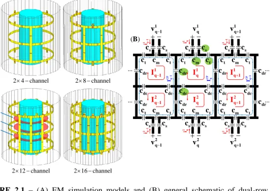
2.1 (A) EM simulation models and (B) general schematic of dual-row degenerate birdcage TxArray coils. Three axial planes are shown in (A) to compare the TxArray coil fields. The port voltages and the mesh currents (the red trace) are shown in each of the loops. CP
q I (the blue trace) denotes the mesh current of the CP excitation mode. All coils have the same dimensions, are enclosed with the same cylindrical RF shields, and are loaded by the same uniform cylindrical phantom. . . 12
2.2 (A) EM simulation models and (B) general schematic of four high-pass birdcage coils. All coils have the same dimensions, are enclosed with the same cylindrical RF shields, and are loaded by the same uniform cylindrical phantoms. . . 13
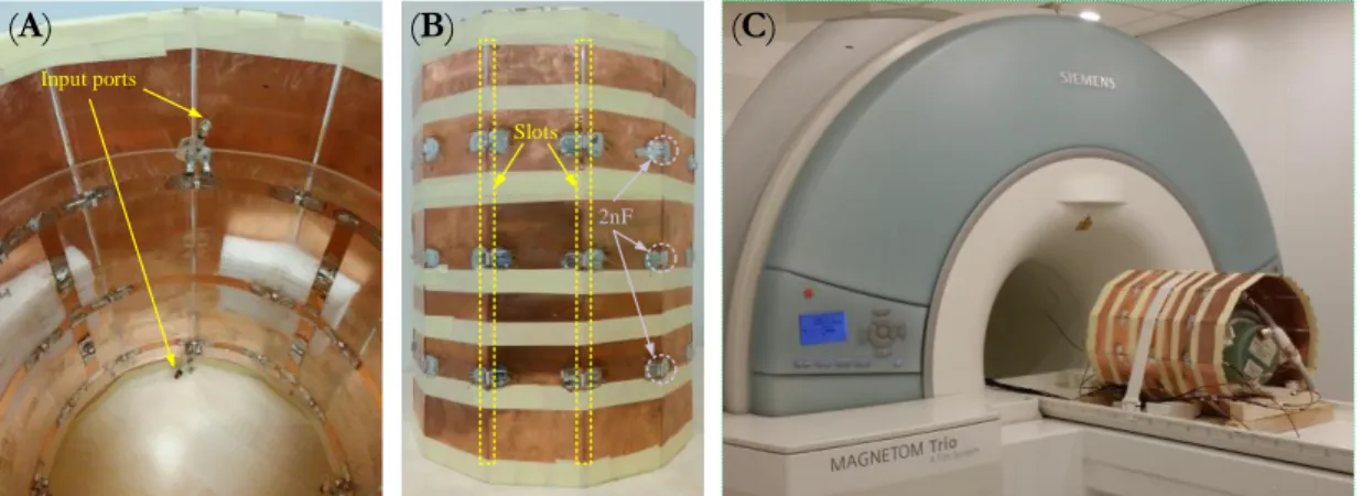
2.3 Experimental setups. (A) A 2×4-channel degenerate birdcage head TxArray coil that was designed and constructed using the proposed method. (B) An RF shield with several parallel slots placed on plexiglass in the shape of a right regular dodecagonal prism. (C) An overview of the TxArray coil inside the scanner. The coil is loaded with the sodium-nickel solution phantom, and the body-matrix coil of the Siemens scanner is used to pick up the MR signals. . . . 16
2.4 (A) Normalized reflected power, (B) total delivered power to the phantom, and (C) B1+ efficiency of N-channel TxArray coil and N/2-rung high-pass birdcage coil, which were both derived in the CP excitation mode with N = 8, 16, 24, and 32. The N-channel TxArray coils were designed based on the -opt (case#1) approach. . . . 20
xiii
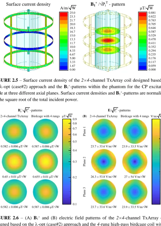
2.5 Surface current density of the 2×4-channel TxArray coil designed based on the -opt (case#2) approach and the B1+-patterns within the phantom for the CP excitation mode at three different axial planes. Surface current densities and B1+-patterns are normalized by the square root of the total incident power. . . . 21 2.6 (A) B1+ and (B) electric field patterns of the 2×4-channel TxArray
coil designed based on the -opt (case#2) approach and the 4-rung high-pass birdcage coil within the phantom at three different axial planes when both coils were driven in the CP excitation mode. The field patterns are normalized by the square root of the total incident power. . . 21
2.7 (A) B1+-patterns of the 2×4-channel TxArray coil designed based on the -opt (case#2) approach within the phantom at the central axial plane (Plane 2) when the coil was derived in the CP excitation mode. (B) B1+ field distributions at y = 0. The field patterns are normalized by the square root of the total incident power. . . 22
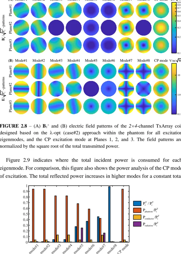
2.8 (A) B1+ and (B) electric field patterns of the 2×4-channel TxArray coil designed based on the -opt (case#2) approach within the phantom for all excitation eigenmodes, and the CP excitation mode at Planes 1, 2, and 3. The field patterns are normalized by the square root of the total transmitted power. . . . 23
2.9 Power analysis of the 2×4-channel TxArray coil designed based on the -opt (case#2) approach for the excitation eigenmodes and the CP excitation mode. . . 23
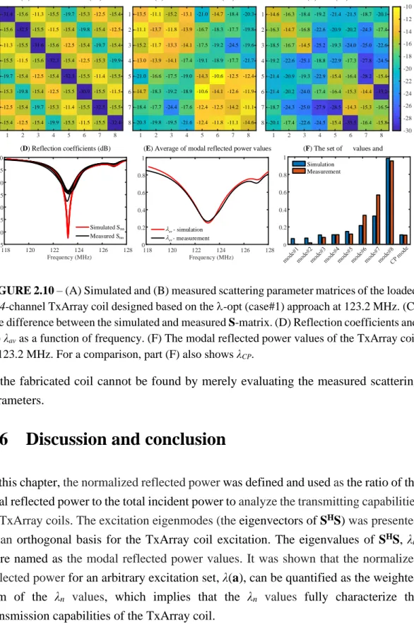
2.10 (A) Simulated and (B) measured scattering parameter matrices of the loaded 2×4-channel TxArray coil designed based on the -opt (case#1) approach at 123.2 MHz. (C) The difference between the simulated and measured S-matrix. (D) Reflection coefficients and (E)
λav as a function of frequency. (F) The modal reflected power values
of the TxArray coil at 123.2 MHz. For a comparison, part (F) also shows λCP. . . . 26
xiv
2.11 Measured (left) and simulated (right) B1+-patterns of the CP excitation mode at the central axial plane (Plane 2) for the fabricated and simulated 2×4-channel TxArray coil designed based on the -opt (case#1) approach. The field patterns are normalized by the square root of the total incident power. In the measured B1+-pattern, phase/magnitude shimming was not performed. . . . 27 3.1 (A) Electromagnetics (EM) simulation model and (B) schematic of a
loaded 8-channel degenerate birdcage TxArray coil. Vq for q = 1, 2,
…, 8 represents the voltage across the port of the qth loop. . . . 32
3.2 The manufactured structure of a shielded 8-channel degenerate birdcage TxArray coil loaded with a cylindrical sodium-nickel solution phantom. The shield is broken down into eight uniformly spaced segments, where the adjacent segments are connected via two 2.5 nF capacitors at positions facing the coil's end-rings. Eight floating current traps were constructed and added to the coil. . . 34
3.3 Equivalent lumped element circuit model of the manufactured 8-channel degenerate birdcage TxArray coil. Although self/mutual-inductances resistances) are considered, only self-self/mutual-inductances (-resistances) are shown in the model. . . . 35
3.4 Simulated and measured (A) reflection coefficients and (B) the average of modal reflected power values, λav, of the 8-channel
TxArray coil with nearly the same capacitor values as a function of frequency. . . 39
3.5 (A) Simulated S-matrix at 123.2 MHz and (B) measured S-matrix at 130.9 MHz of the 8-channel TxArray coil. (C) Difference between the simulated S-matrix at 123.2 MHz and measured S-matrix at 130.9 MHz. . . . 40 3.6 Simulated and measured (A) reflection coefficients and (B) the
average of modal reflected power values, λav, of the 8-channel
xv
obtained with the initial capacitor values (cd = 12.8 pF, ct = 9.5 pF, cm
= 34.7 pF, and cs = 10.5 pF), while the measurement results were
achieved with the new capacitor values (cd = 14.5±0.1 pF, ct =
10.6±0.7 pF, cm = 40.4±0.2 pF, and cs = 12.9±0.1 pF). . . 40
3.7 Simulated and measured modal reflected power values of the 8-channel TxArray coil at 123.2 MHz. For comparison, λCP is also
shown. Simulated λ values were obtained with the initial capacitor values (cd = 12.8 pF, ct = 9.5 pF, cm = 34.7 pF, and cs = 10.5 pF), while
the measured λ values were achieved with the new set of the capacitor values (cd = 14.5±0.1 pF, ct = 10.6±0.7 pF, cm = 40.4±0.2 pF, and cs
= 12.9±0.1 pF). . . 41
3.8 (A) Simulated and (B) measured S-matrices of the 8-channel TxArray coil at 123.2 MHz. (C) Difference between the simulated and measured S-matrices at 123.2 MHz. Simulated S-matrix was obtained with the initial capacitor values (cd = 12.8 pF, ct = 9.5 pF, cm = 34.7
pF, and cs = 10.5 pF), while the measured S-matrix was achieved with
the new capacitor values (cd = 14.5±0.1 pF, ct = 10.6±0.7 pF, cm =
40.4±0.2 pF, and cs = 12.9±0.1 pF). . . 42
4.1 (A) Electromagnetics (EM) simulation model and (B) schematic of an unloaded 12-channel degenerate birdcage TxArray coil. Vq for q = 1,
2, …, 12 refers to the input voltage across the qth port. . . 48 4.2 Equivalent circuit model of an unloaded 12-channel degenerate
birdcage TxArray coil. Although both self- and mutual-inductances of the coil are considered in the equivalent circuit model, only the self-inductors are shown in the model. . . . 49 4.3 (A) EM simulation model of an unloaded 12-channel degenerate
birdcage TxArray coil enclosed by a cylindrical shield. (B) The original and imaginary TxArray coils. The cylindrical shield is replaced with an imaginary coil. (C) The original and imaginary segmentized TxArray coils. . . 52
xvi
4.4 (A) Two parallel rung conductors with uniformly currents distributed along the φ-axis and (B) two parallel end-ring conductors with uniformly currents distributed along the z-axis. . . 53
4.5 EM simulation models of two shielded 12-channel degenerate birdcage TxArray coil loaded by a uniform cylindrical phantom with the minimum (left TxArray coil) and maximum (right TxArray coil) possible EF values. . . . 57
4.6 Analysis performance of 8 loaded 12-channel degenerate birdcage TxArray coils designed by min{λav} approach with different rc
ranging from 140 mm to 195 mm when lc = 260 mm, wring = 40 mm, wrung = 10 mm, and rs = 200 mm. (A) Reflection coefficient and
maximum coupling, (B) λav and λCP, (C) B1+ efficiency in the CP
mode, and (D) power analysis in the CP mode. . . 60 4.7 Analysis performance of 8 loaded 12-channel degenerate birdcage
TxArray coils designed by min{λav + λCP} approach with different rc
ranging from 140 mm to 195 mm when lc = 260 mm, wring = 40 mm, wrung = 10 mm, and rs = 200 mm. (A) Reflection coefficient and
maximum coupling, (B) λav and λCP, (C) B1+ efficiency in the CP
mode, and (D) power analysis in the CP mode. . . 61 5.1 CT images of patients with isolated and fully implanted DBS devices.
(A) Patient with bilateral leads prior to their connection to the implantable pulse generator (IPG). Labels "contralateral" and "ipsilateral" are with respect to the body side that the IPG is planned to be implanted later. (B) A patient with a fully implanted DBS system consisting of two IPGs, two leads, and two extension cables connecting leads to the IPGs. . . 67 5.2 Overview of the working principle of the rotating coil system. A
linearly polarized birdcage transmitter has a slab-like region of low electric field. The orientation of this low E-field region can be steered by mechanically rotating the coil around patient's head. The heating of conductive wire implants can be minimized when they are
xvii
maximally contained within this low field region. In this figure, the coil input power is adjusted to produce a mean B1+ = 2 µT on a central axial plane passing through the head. . . . 69 5.3 Reconstructed models of DBS leads registered in a head phantom for
finite element simulations. CT images of 12 patients with isolated leads and one patient with a fully implanted system were used to extract lead trajectories. Models of electrode contacts and the insulation were built around each trajectory. . . 71 5.4 (A) Spatial distribution of 1g-averaged SAR around DBS contact
leads. The maximum of local SAR was calculated inside a cubic area surrounding all four electrode contacts. (B) The spatial distribution of B1+ field on a central axial plane. For all simulations, the input power of the coil was adjusted to produce a B1+ field with a spatial mean of 2 µT. (C-D) Finite element mesh in the area surrounding the leads and on the electrode contacts. Mesh resolution was < 0.7 mm in the cubic area surrounding the leads and < 0.3 mm on the electrode contacts. . . 72 5.5 Model of a typical high-pass CP birdcage coil at 3T. The body model
has been extended to the chest to load the body coil properly. . . . 73 5.6 The maximum of 1g-averaged SAR calculated around tips of left and
right DBS leads as a function of rotating coil angle φ° (solid lines). The input power of the coil is adjusted to generate a mean B1+ = 2 µT on a central axial plane. The maximum of 1g-averaged SAR is also given for the body coil generating the same mean B1+ = 2 µT (dashed-lines). . . . 74 5.7 (A) curved mayo scissors with blades opened to the max were used to
create a pocket for the looped leads to be inserted. (B) Leads were looped 2-3 turns concentrically and placed on top of the surgical burr hole. . . .. . . 78 5.8 Postoperative CT image of a patient implanted with bilateral DBS
leads connected to a double-channel pulse generator implanted in the right pectoral region. Concentric loops were incorporated into lead
xviii
trajectories at the surgical burr hole. The rest of the lead trajectories and extension cables were aligned and overlapped to follow the same path. A model of the patient's silhouette and the fully implanted device was constructed based on the CT image for finite element simulations. . . . 78 5.9 The maximum of 1g-averaged SAR calculated around tips of left and
right DBS leads of patient #14 as a function of rotating coil angle φ° (solid lines). The input power of the coil is adjusted to generate a mean B1+ = 2 µT on a central axial plane. The maximum of 1g-averaged SAR is also given for the body coil generating the same B1+ (dashed-lines). As expected, when lead trajectories are overlapped the SAR profiles of right and left leads vary very similarly as a function of the coil rotation angle. This significantly enhances bilateral SAR reduction by allowing simultaneous SAR minimization at the tips of both leads at a common optimum angle. . . . 79 5.10 Maximum of 1g-averaged SAR in the tissue of patients 5 and 14 as a
function of different coil rotation angles and at different values of tissue conductivity. The predicted optimum angle of the coil was insensitive to changes in the change of tissue's electrical property. . . 81 6.1 Geometry configuration of (A) 1.2T high-pass radial planar birdcage
coil and (B) 1.5T high-pass birdcage coil. . . 89 6.2 B1+ and E fields distributions of (A-B) 1.2T vertical coil and (C-D)
1.5T horizontal coil within a human body model with no implants. Both coils' input power is adjusted to generate a mean B1+ = 4 μT over a circular plane placed on an axial plane passing through the coils' iso-center. . . 90 6.3 Coil configuration of 1.2T vertical and 1.5T horizontal coils loaded
with a human body model placed at two different positions corresponding to head and chest imaging. . . 91 6.4 (A) Examples of postoperative CT images of three patients (patient
xix
with approval form Northwestern University's ethics review board. Lead trajectories were extracted using CT images of 20 patients with bilateral DBS implantation (patient numbers ID1-ID20) and were registered in a homogeneous body phantom for electromagnetic simulations. . . . 91 6.5 Reconstructed models of isolated DBS leads with approval from
Albany Medical College's institutional review board. Lead trajectories were extracted using CT images of 12 patients with bilateral DBS implantation (ID21-ID32) and 14 patients with unilateral DBS implantation (ID33-ID46) were all registered to a standard homogeneous head and torso model. . . 92 6.6 Reconstructed models of fully implanted DBS systems. Lead
trajectories were extracted using CT images of 5 patients with bilateral DBS implantation (ID47-ID51) and two patients with unilateral DBS implantation (ID52-ID53) were all registered in their corresponding homogeneous body models for electromagnetic simulations. . . . 93 6.7 Local SAR distributions in patient 47 (ID47) for the 1.2T OASIS coil
and 1.2T and 1.5T horizontal birdcage coils all with head and chest landmarks on an axial plane that passes through the tips of implants. In all maps, the coil's input power is adjusted to generate a mean B1+ = 4 μT over a circular plane placed on an axial plane passing through the coil's iso-center. . . . 95 6.8 Local 0.1g-SARmax over 90 leads shown for the 1.2T vertical coil and
1.2T and 1.5T horizontal coils for head and chest landmarks. Box and whisker plot are showing data range, median, and interquartile range (IQR). The outliers were plotted individually using a red '+' symbol. . 95
xx
List of Tables
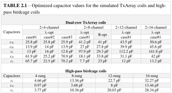
2.1 Optimized capacitor values for the simulated TxArray coils and high-pass birdcage coils. . . 15 2.2 Optimized capacitor values for the fabricated and simulated
2×4-channel TxArray coils. . . 16 2.3 Summary of the performance of the simulated TxArray coils designed
based on the different minimization approaches. . . 18 2.4 Sensitivity of the eigenvalues to the conductivity of the phantom. . . . 24 2.5 Sensitivity of the eigenvalues to the phantom diameter. . . . 25 4.1 Summary of the performance of the simulated TxArray coils designed
based on the minimum and maximum possible EF values. . . 58 5.1 Maximum of unilateral and bilateral SAR Reduction Efficiency
(SREUni,n,i and SREBi,n) for each patient and their corresponding
optimum coil rotating angles. . . 76 5.2 Sequences and scan parameters used in typical brain exams and in
thermal simulations. Here TR refers to repetition time, TE to echo time, FOV to field of view, FA to flip angle, and ST to slice thickness. 82 6.1 Computation space and time for each simulation of the OASIS coil
and horizontal birdcage coil. . . . 94 6.2 Maximum of 0.1g SAR. .. . . 96
1
Chapter 1
Introduction
Magnetic resonance imaging (MRI) is a non-invasive and powerful medical imaging tool. MRI is one of the most popular imaging modalities for diagnosis purposes. Indeed, MRI could penetrate deep into tissue with minimal risk for the patient and provide an outstanding soft-tissue contrast. MRI has been at the forefront of many researchers' interest throughout its existence, owing to its significance in clinical applications. Technological advancements developed and tested in the world's research laboratories continue to improve the flexibility and efficiency of MRI scanners. However, the evidently untapped capacities which remain could be the most interesting relative to the development of MRI.
The MRI principality is constructed from the main magnet with an intense static field (∼ T), radiofrequency (RF) coil (∼ µT), and three gradient coils with orthogonal fields (∼ mT/m). RF coils serve to both stimulate and receive the MRI signal and can be categorized as transmit only, receive only, and transmit/receive (transceiver) coils. An informed specification, design, implementation, assessment, and application of appropriately selected RF coils will provide a safe and efficient MRI test. Since the earliest days of the MRI scanners, researchers have been finding ways to develop RF coils. In fact, RF coils have developed from the simplistic single-channel coils to the complicated multi-channel coils designed for modern applications. Developed multi-channel technology for RF coils with array elements have found new and more essential applications in parallel transmit schemes and parallel imaging to further enhance imaging quality, speed, and safety.
2
The RF frequency for proton MRI has also risen as MRI has shifted to greater field strengths. Partly because of the human body's electrical characteristics and partially because of the physical scale, the RF excitation homogeneity reachable with one channel transmit coil sometimes is not sufficient for reliable clinical diagnosis in some applications and with some patients [1, 2]. Full-body electromagnetic (EM) field simulations demonstrate considerable RF inhomogeneity (dielectric shading) and local SAR variations for the typical clinical RF coils used today, which eventually restrict scan speed [3, 4].
Radiofrequency (RF) transmit array (TxArray) coils, using multiple RF transmit coil elements in parallel, are being extensively utilized in ultra-high field MRI to overcome different issues, such as RF excitation inhomogeneities [5-15]. TxArray coils can be very useful for conventional high-field scanners since they provide additional degrees of freedom to the designers of pulse sequences and enable RF shimming while attempting to suppress SAR [16-18] hotspots. Besides, these degrees of freedom are useful for increasing power efficiency [19-21] and accelerating RF-intense applications [15]. TxArray coils can also be beneficial for the implementation of the implant-friendly mode [22-25]. It follows that TxArray coils are critical for obtaining the maximum benefit from high-field MRI.
TxArray coil's performance can gain considerably from the parallel transmission technology when the coil designs meet particular specifications, such as low coupling among individual array elements and appropriate interaction with subjects under test to provide a sufficient B1+ field [26] efficiency. The high coupling level causes extra reflected power from the TxArray coil and decreases the power delivered to the subject, which is consequently considered a significant design challenge [21].
Numerous approaches are employed to reduce the effective coil coupling, including the use of L/C decoupling networks [27-30], overlapping of neighboring array elements [31, 32], transformer decoupling [33], inserting the induced current elimination (ICE) decoupling elements [34, 35], and adding reactive decoupling circuits among adjacent array elements [36]. Increasing the number of array elements will increase degrees of freedom for shimming and enhance excitation encoding capabilities of TxArray coils. The high coupling among individual array elements conversely decreases these degrees of freedom as B1+ patterns of the array elements become more similar. However, as the number of array elements increases, the
3
coupling issue becomes more challenging because it requires further decoupling components and longer RF cables to decouple non-neighboring array elements [21, 37, 38]. Owing to the factors mentioned above, it is far more challenging to design TxArray coils than conventional coils. Therefore, part of this dissertation introduces novel design techniques for TxArray coils.
Correspondingly, chapter 2 introduces the concept of the scattering (S) matrix eigenmode analysis. Using this concept, a general design technique for obtaining efficient operation modes of TxArray coils is developed. It is demonstrated that eigenmode analysis of the S-matrix is an efficient method that provides a quantitative and compact representation of the TxArray coil's power transmission capabilities. This method offers a simple tool for quantifying, comparing, and optimizing the performance of the TxArray coils. It is shown that the ratio of the total reflected power to the total incident power of TxArray coils for a given excitation signal is the weighted sum of the eigenvalues SHS-matrix where the superscript H denotes the Hermitian
transpose. Minimizing the eigenvalues of SHS-matrix can increase the excitation space
of TxArray coils with a low total reflection. This chapter also presents a new and efficient methodology for designing TxArray coils based on minimizing the total reflected power for certain operating modes. It shows that the low total reflected power for some critical excitation modes can be achieved for all TxArray coils, even with a high coupling level. The method can enable the coil designers to find the maximum possible number of efficient modes for a TxArray coil with an arbitrary number of channels by optimizing the free design parameters. The performance of various 3T TxArray coils is investigated using the proposed method together with simulations and experiments.
Chapter 3 presents a fast fine-tuning method for designing an imperfectly manufactured TxArray coil using its equivalent circuit model. In a typical transmit coil building process, the general structure of the coil is designed, and its capacitor values are found using various optimization processes [39, 40], which may include an electromagnetic field simulation. The imperfections in the manufacturing process result in poor performance. The coil has to be fine-tuned to improve its performance. Although the fine-tuning process is rather straightforward when the number of coil elements is low, it becomes challenging for a coil with a high number of channels. This chapter proposes to fit the measured S parameters to an equivalent circuit model
4
to estimate all self/mutual-inductances and self/mutual-resistances of the manufactured coil, and then to find the capacitors that fine-tune the coil. The fine-tuning process of a 3T TxArray coil is accelerated using the proposed method, and it is demonstrated that the fabrication could be done only in a single iteration.
Chapter 4 lays out a TxArray coil design strategy based on minimizing the magnetic coupling between non-adjacent transmit array elements. According to the proposed method, the TxArray coil's design has changed from a traditional single-stage procedure to a two-stage procedure. A vast majority of design strategies are based on optimizing the capacitor values for a TxArray coil with predefined geometry. The method presented in this chapter focuses on optimizing the coil's sizes, before optimizing capacitors, to decrease the mutual-inductances between non-adjacent array elements. As a sample design, a 3T TxArray coil's optimum dimensions, such as coil radius, coil length, copper widths, are determined. Finite element based simulations are performed to confirm the validity of the method.
Although the magnetic component of the RF field stimulates the MRI signals, the corresponding electric field is the cause of bioeffects. Nerve stimulation and tissue heating, principally, are the instant bioeffects of RF fields [41]. Thus, safety consideration has been one of the most critical research topics in MRI. The localized
specific absorption rate (SAR) concentration due to the interaction of metallic medical implants with electric fields is one of the essential safety considerations of RF coils. There has recently been considerable attention paid to the measurement of implant heating and the development of computational methods for implant safety assessments. Therefore, part of this dissertation is dedicated to RF safety assessment of patients with metallic implants.
MRI of patients with deep brain stimulation (DBS) implants is highly beneficial, both for target verification and to assess the "connectomics" functional effects of the neuromodulation [42]. Unfortunately, the interaction of RF fields with elongated DBS leads causes safety concerns that restrict MRI accessibility to these patients. Recent studies are mostly based on steering electric-field free regions in RF transmit coils through the design of implant-friendly modes using parallel transmit technology [22, 43-45]. Rendering the parallel transmit strategy is, however, complicated for ordinary applications in the clinic. Recently, a reconfigurable MRI technology with a rotating transmit coil was introduced, which offers an easy operational setup yet significant
5
reduction in SAR near tips of unilateral DBS leads during MRI at 1.5T [46, 47]. Chapter 5 presents the feasibility of using such reconfigurable coil technology for DBS imaging at 3T. This is the first study to assess the performance of field-steering based methods to simultaneously reduce the SAR at tips of bilateral DBS leads, use patient-derived realistic models, and consider both isolated leads and fully-implanted DBS systems with different configurations.
The majority of studies on RF heating of conductive implants, as well as the MR-labeling of DBS devices, have been limited to horizontal close-bore MRI scanners. Vertical MRI scanners introduced initially as open low-field MRI systems, are now available at 1.2T field strength, capable of high-resolution structural and functional imaging. No literature exists on DBS SAR in this class of scanners, which have a 90 rotated transmit coil and thus, generate fundamentally different electric and magnetic field distributions. Chapter 6 presents a simulation study of RF heating in a cohort of 90 patient-derived DBS lead models during MRI in a commercially available vertical open-bore MRI system (1.2T OASIS, Hitachi) and a standard horizontal 1.5T birdcage coil. It is shown that the open-bore vertical MRI system generates a significantly less SAR around implanted DBS leads. This SAR reduction is consistent over a large and diverse patient population with both types of isolated and fully implanted systems operated at two DBS centers.
Overall, this dissertation introduces innovative TxArray coil design techniques and evaluates RF heating in patients with implanted DBS leads to mitigate SAR during MRI scan, which primarily translates to improving the performance of RF transmit coils in terms of power efficiency and patient safety.
6
Chapter 2
Eigenmode Analysis of the Scattering
Matrix for the Design of MRI Transmit
Array Coils
2.1 Preface
The content of this chapter was partially presented at the International Society of Magnetic Resonance in Medicine (ISMRM)'s 27th and 28th Annual Scientific Meetings [48, 49], and published in Magnetic Resonance in Medicine [50]. The text, figures, and tables presented in this chapter are all based upon the journal publication [50]. Ergin Atalar has been involved in the conceptualization and methodology of the content of this chapter. The phantom experiments were conducted by the help of Alireza Sadeghi-Tarakameh.
2.2 Introduction
The performance of Radiofrequency (RF) transmit array (TxArray) coils significantly profits from parallel transmit technology if the coil designs satisfy particular requirements, such as low mutual coupling between individual array elements and sufficient interaction with samples to ensure sufficiently high power efficiency. High coupling among array elements makes power delivery to the subject challenging and, therefore, is considered a major design issue [21]. Increasing the number of transmit
7
elements can enhance the capability of TxArray coils in terms of RF shimming and homogeneity. The problem of mutual coupling reduction becomes more complex as the number of array elements increases due to the need for more decoupling components and longer cables to decouple non-adjacent elements, which are distantly located [21, 37, 38]. Considering the cost of high-power RF amplifiers, improvements in the incremental performance by further transmit elements with realistic assumptions of power budget for particular TxArray coil geometries and configurations should be determined. Theoretically, the power efficiency of a TxArray coil under single-channel excitation depends on the amount of power coupled to other transmit elements and is reflected back to the amplifier. The reflected power does not produce the B1+ field [26] within the sample and may cause damage to the amplifiers [21, 51]. In this situation, proper matching, tuning, and decoupling of a TxArray coil produce higher transmitted power from the amplifier to the transmit elements and lower reflected power from all transmit elements [21, 52]. For a TxArray coil with coupled transmit elements under multichannel excitation, the total reflected power depends on the phases and amplitudes of the RF excitation signals, as well as the levels of matching, tuning, and decoupling. Although multiple studies focused on optimizing the excitation signals with various strict constraints, including the power consumption of TxArray coils [21, 53-57], categorization of the inputs based on the transmitted and reflected power in TxArray coils warrants attention.
Here, the concept of excitation eigenmodes is presented to achieve a quantitative and compact representation of the TxArray coil's transmission capabilities. For a given set of excitation signals, the total power transmitted to a TxArray coil can be analyzed using its scattering matrix (S-matrix), which can be determined as a relationship between the incident waves and reflected waves. The eigenmode analysis of S-matrix
provides insight into the excitation signals with a low level of reflected power. It offers a simple tool for quantifying, comparing, and optimizing the performance of the TxArray coils.
An ideal TxArray coil in terms of the power efficiency will have a zero total reflected power for all incident waves, which requires a zero S-matrix. Due to the practical limitations and imperfections in matching and decoupling, S-matrix cannot be zero. However, the S-matrix elements can be minimized by adjusting the geometrical parameters or capacitor values of the coil using an optimization process.
8
In this process, the optimization criterion is fundamental and affects the performance of the coil [58]. The vast majority of studies concentrated on minimizing the magnitude of S-matrix elements without considering the excitation signals [38, 59-61]. However, the excitation signals have a significant role in determining the total transmitted and reflected power levels [58]. For a given TxArray coil, the reflection can be high for some excitation signals but low for some others. Here, it is proposed that the eigenmode analysis, looking at the S-matrix as a whole, captures more than just looking at the S-matrix elements individually. In this new matrix analysis, in addition to the magnitude of the S-matrix elements, their phases are also included, which was previously ignored. The insight provided by this approach can be used to minimize the total reflected power for larger sets of excitation signals by adjusting the TxArray coil design parameters. The novel design strategy utilized in this chapter demonstrates the possibility of obtaining very low total reflected power for specific sets of excitations, even for TxArray coils with a nonzero S-matrix.
In this chapter, the theory and concept of the S-matrix eigenmode analysis are provided, the details of the TxArray coil design are discussed, and the optimization strategy used to adjust the capacitor values to minimize the total reflected power is explained. A variety of simulation and experiment results on four dual-row TxArray coils with a different number of channels for imaging at 3T scanners are also provided. These coils [62, 63]have a significant potential to replace the conventional body coils since they can perform similar to the traditional birdcage coils if they are driven in the circularly polarized (CP) form but also provide additional degrees of freedom for many valuable applications of the TxArray coils.
2.3 Theory
The S-matrix describing a TxArray coil characterizes all the power interactions between its input ports. For a generic TxArray coil consisting of N transmit elements, the S-matrix is represented as b = Sa, where a and b are the vectors of the incident and reflected waves, respectively, defined as
* 0 0 0 0 1 1 ( ) and ( ) 2 | {Z }| Z 2 | {Z }| Z = + = − a V I b V I (2.1)
9
where V and I are the vectors of root-mean-square port voltages and currents. Z0 is the
reference impedance and is chosen as 50 ohms in this chapter. With this formulation, the total average power transmitted to a TxArray coil with lossless transmission lines can be written as [64]
( )
T t
P =a aH −b bH =aH U−S S aH (2.2) where the superscript H denotes the Hermitian (conjugate) transpose, and U denotes the identity matrix. Equation (2.2) expresses the net transmitted power as the difference between the incident power and the reflected power, which can be quantified as T
i
P =a aH and T r
P =b bH , respectively. A perfect design has 100%
transmitted power and no reflected power, which does not occur when the transmit coil elements are coupled. The ratio of the total reflected power to the total incident power can be defined as the normalized reflected power. The normalized reflected power can be characterized as a function of the excitations and S-matrix
( ) T r T i P P a = =b bHH =a S SaH HH a a a a (2.3)
λ(a) can be minimized to ensure high transmit efficiency.
Examining SHS can provide information on the total incident and reflected power
of a TxArray coil [65, 66]. SHS is a Hermitian matrix, which is therefore
diagonalizable by a unitary similarity transformation [67]. Hence =
H H
S S Q Q (2.4)
where Q is a unitary matrix (i.e., QQH = QHQ = U) formed by the eigenvectors (
n q ) of SHS. Λ is a diagonal matrix formed by the eigenvalues (λn) of SHS.
If the TxArray coil is excited in such a way that the vector of the incident waves is equal to the nth eigenvector of SHS, i.e.,
n
=
a q , then the normalized reflected power yields ( ) n n n n n n n n n n n a=q =b bHH =q S SqH HH =qHH q = a a q q q q (2.5)
10
because [S S qH ] n =nqn. It should be noted that all eigenvalues are positive real with values less than or equal to one [68]. The eigenvectors of SHS are orthogonal [68] and
represent the excitation vectors of the TxArray coil. Therefore, they shall be called the
excitation eigenmodes of the TxArray coil, and the eigenvalues of SHS shall be called
the modal reflected power values of the TxArray coil. The normalized reflected power in the case of an arbitrary vector of incident waves, which can be uniquely expanded as a sum of the distinct eigenmodes, that is,
1 N n n n w = =
= a q Qw , where
w1 w2 ... wN
= Tw is the vector of the expansion coefficients, can be expressed as follows 2 1 ( ) N n n n w = = = = = =
H H H H H H H H H H H H H H H a S Sa w Q S SQw a a a w Q Qw w Q Q Q Qw w w w Q Qw w w w (2.6)Equation (2.6) shows that the normalized reflected power can be represented as the normalized weighted sum of the modal reflected power values. Because the form of
λ(a) is a Rayleigh quotient [69], its values are always between the smallest and largest λn values [65]. To obtain an ideal TxArray coil with zero total reflected power for any
arbitrary inputs, all eigenvalues of SHS must be zero, which does not appear to be
feasible. However, the parameters in determining SHS can be adjusted to minimize all
eigenvalues and achieve a low total reflected power for a broader set of incident waves.
2.4 Methods
2.4.1 -opt design strategy
In this chapter, a design strategy based on the minimization of the normalized reflected power was employed to obtain the capacitor values of TxArray coils, known as -optimization (-opt). This strategy minimizes the normalized reflected power for excitation eigenmodes as well as for the CP excitation vector, that is, λCP. Minimizing λCP provides the opportunity to compose the CP excitation mode from the most
11
efficient excitation eigenmodes. However, the optimization problem was formulated as
(
2)
2 1 -opt: min N n n CP CP n = +
c (2.7)where c is the vector of the capacitor values and N is the total number of channels. αn
and αCP represent the weights for each term. A constraint can be added to Equation
(2.7) to obtain desired modes of operations. This general formulation was used under three specific cases:
2 2 1 2 2 1 2 1 1 case#1 min 1 min -opt: case#2 s.t. 0.01 1 case#3 min N n CP n N n CP n CP N n n N N N = = = + +
c c c (2.8)These three different minimization cases were employed to investigate the impact of the added constraint and weighting coefficients on the optimization results. To compare the performance of the -opt strategy, the conventional minimization strategy [20, 39, 52, 70], which is based on minimizing the magnitude of the S-matrix elements individually (S-opt), was also implemented. For this, the difference between the actual and desired S-matrices was minimized, as described in Ref. [39]. Therefore, this optimization criterion was formulated as
2 1 1 1 min | | -opt: s.t. | | 15 dB N N mn n m nn s N s = = −
c S (2.9)The added constraint puts an upper limit on the reflection coefficients. Note that
2 1 1 | | N N mn n m s = =
, which is equal to the trace of SHS, can also be calculated as thesummation of the λn values [67]; therefore, the S-opt approach minimizes the average
of the λn values denoted as λav, while limiting the reflection coefficients to be equal to
12
2.4.2 Proposed model for RF TxArray coil
The proposed model and schematic of dual-row (2×N
2 -channel) head TxArray coils
are shown in Figure 2.1. These coils have a cylindrical geometry, is composed of N transmit loops with the same dimensional sizes distributed in both the circumferential direction and the z-direction, and can be decoupled (approximately) by adjusting the decoupling capacitors placed between the nearest neighbors. In each loop, five distinct capacitor values, that is, c =[cdr cdc ct cm cs], mainly control the performance
of the TxArray coils as free design parameters. The chosen structure for the dual-row TxArray coil enables the coil to act like a single-row degenerate birdcage TxArray coil [29, 30, 62, 63, 71-74] when the mesh currents of the adjacent elements in the axial direction cancel each other in the mid-ring segments of the coil. In the CP excitation mode, both rows are individually excited with identical power and linearly increasing phases, and the lower-row channels are excited with a 180° phase shift relative to the
(A) Plane 1 Plane 2 Plane 3 (B) − 1 q 1 I − 1 q 1 v − 1iq1 dc c m c t c m c − 2 q 1 I t c − + − 2 q 1 v − 2iq1 dr c s c s c s c s c dr c t c t c dc c 1 q I 1 q v 1iq dc c m c t c m c 2 q I t c 2 q v 2iq dr c s c s c s c s c dr c t c dc c + 1 q 1 I + 1 q 1 v + 1iq1 dc c m c t c m c + 2 q 1 I t c + 2 q 1 v + 2iq1 dr c s c s c s c s c dr c t c t c dc c t c − CP q1 I CPIq CP +q1 I dr c dr c − + +− − + +− +− 2 4 channel − 2 8 channel − 2 12 channel − 2 16 channel −
FIGURE 2.1 – (A) EM simulation models and (B) general schematic of dual-row degenerate birdcage TxArray coils. Three axial planes are shown in (A) to compare the TxArray coil fields. The port voltages and the mesh currents (the red trace) are shown in each of the loops. CP
q
I (the blue trace) denotes the mesh current of the CP excitation mode. All coils have the same dimensions, are enclosed with the same cylindrical RF shields, and are loaded by the same uniform cylindrical phantom.
13
upper-row channels. When the CP excitation is applied to this coil, it produces a field similar to a conventional birdcage coil with a rather uniform B1+ field distribution in a large field-of-view.
2.4.3 Numerical simulations
Four shielded dual-row TxArray coils at 3T with 4, 8, 12, and 16 transmit channels in each row were designed and simulated (Figure 2.1). Additionally, four high-pass birdcage coils at 3T composed of 4, 8, 12, and 16 rungs connected at each end to two end-rings, as shown in Figure 2.2A, were simulated to compare the B1+ patterns of the
TxArray coils in the CP excitation mode with the traditional birdcage coils. The birdcage coils were tuned by capacitors distributed at the end-rings gaps (ct) and
matched to 50 Ω using two different capacitors: one at the top end-ring gap (cm)
connected in parallel to another capacitor (cs) which is in series with an ideal voltage
source (Figure 2.2B). The capacitors in the simulation of the high-pass birdcage coils were adjusted to produce a uniform magnetic field. However, the birdcage coils have
4 rungs− 8 rungs− 12 rungs− 16 rungs− (A) (B) 1 v m c t c s c t c − +v2 t c m c t c s c − +
FIGURE 2.2 – (A) EM simulation models and (B) general schematic of four high-pass birdcage coils. All coils have the same dimensions, are enclosed with the same cylindrical RF shields, and are loaded by the same uniform cylindrical phantoms.
14
two decoupled ports on the top end-ring that were driven in the quadrature mode, where their ports were fed with the same amplitudes but with a 90° phase differential.
All TxArray coil and birdcage coils had a cylindrical geometry with the same dimensions (diameter of 315 mm, length of 270 mm, shield diameter of 408.9 mm, and shield length of 420 mm). All rings and legs were copper strips with a width of 15 mm. All coils shown in Figures 2.1-2.2 were loaded with a uniform cylindrical phantom with a diameter of 160 mm, a length of 350 mm, a conductivity of 0.6 S/m, and a relative permittivity of 80.
ANSYS Electronics Desktop 18.2 (ANSYS Inc., Canonsburg, PA, USA) was used to implement the numerical simulations at the operation frequency of 123.2 MHz. The conductors were modeled as good conductors [75], and the finite conductivity boundary was defined for them. A sphere with a radius greater than a quarter of the wavelength with the radiation boundary condition was defined as the outer surface of all simulations. Capacitors were adjusted based on the optimization method explained in the previous section using a combined finite element method and circuit analysis approach [76]. By substitution of all capacitors with equivalent lumped ports, the multiport S-matrices of the loaded TxArray coils were calculated in ANSYS HFSS. The multiport S-matrices were applied to perform the minimization problem, which was implemented in custom-written MATLAB 2018b scripts and obtain the optimal values of the capacitors. These MATLAB scripts are openly available in GitHub at https://github.com/UMRAM-Bilkent/Eigenmode-Analysis. In the next step, the multiport S-matrices were exported to ANSYS Designer. The updated port current and voltage values were pushed back to ANSYS HFSS to calculate the distributions of the electric and magnetic fields.
To obtain the capacitor values of the 2×4-channel TxArray coil, all three different minimization cases of the -opt method were studied. The -opt (case#1) approach was also used to determine the coil performance as a function of the number of channels. To evaluate the performance of the proposed optimization strategy, both the -opt (case#1) and S-opt approaches were employed to optimize a 2×8-channel TxArray coil. The capacitor values in the simulation of the TxArray coils and the high-pass birdcage coils are listed in Table 2.1.
15
To obtain more information about the total transmitted power to each TxArray coil, the power loss in phantom and conductors, including the power-loss in the shield, were calculated. The capacitors are assumed to be lossless. The radiation loss was calculated as the difference between the total transmitted power and all other losses.
The B1+ efficiency was evaluated as the average B1+ within a region of interest for a unit total incident power. For comparison of the performance of the coils, the electromagnetic fields were recorded from three different axial planes that pass through the phantom, as shown in Figure 2.1A.
2.4.4 Measurements
To validate the simulations, the structure of a 2×4-channel TxArray coil, which was supported by cylindrical plexiglass with a thickness of 3 mm and an outer diameter of 315 mm (Figure 2.3A), was constructed. The length of the coil was 270 mm, and all rings and legs were copper strips with a width of 15 mm. The coil's copper is broken into 56 different sections to distribute the capacitors. Due to practical limitations, the shield was built on another plexiglass in the shape of a right regular dodecagonal prism (Figure 2.3B). The shield is also constructed of copper strips on the outer side of the frame and slit in 12 equally spaced rectangular sections with dimensions of 105.5×480 mm2 along the axial direction to reduce gradient-induced eddy currents [77]. The neighboring slits were connected with three 2 nF capacitors at positions that face rings
TABLE 2.1 – Optimized capacitor values for the simulated TxArray coils and high-pass birdcage coils
Dual-row TxArray coils
Capacitors
2×4-channel 2×8-channel 2×12-channel 2×16-channel
-opt -opt
S-opt -opt -opt
case#1 case#2 case#3 case#1 case#1 case#1
cdr 25.8 pF 25.8 pF 25.9 pF 41.2 pF 41 pF 43.5 pF 50.6 pF
cdc 13.9 pF 14 pF 13.9 pF 27 pF 27.8 pF 39.9 pF 45.6 pF
ct 13 pF 16 pF 12.8 pF 97.9 pF 29.3 pF 112.2 pF 161.8 pF
cm 61.9 pF 25.2 pF 70.9 pF 18.1 pF 33.8 pF 31.1 pF 42 pF
cs 65.7 pF 22.5 pF 70.2 pF 7.7 pF 23 pF 12 pF 13.2 pF
High-pass birdcage coils
Capacitors 4-rung 8-rung 12-rung 16-rung
ct 4.66 pF 13.36 pF 22.7 pF 32.27 pF
cm 0.97 pF 3.68 pF 8 pF 13.46 pF
16
of the coil. The strip thickness in both the coil and the shield was 35 μm. The coil was loaded with a cylindrical SNR phantom (3.7 g/L NiCl2.6H2O and 2.4 g/L NaCl) with a diameter of 153 mm. Magnetic resonance electrical properties tomography (MREPT) [78] was used to measure the conductivity of the phantom as 0.62 S/m. Its relative permittivity was assumed to be equivalent to that of water [79, 80].
(C)
(A) (B)
Slots
2nF
Input ports
FIGURE 2.3 – Experimental setups. (A) A 2×4-channel degenerate birdcage head TxArray coil that was designed and constructed using the proposed method. (B) An RF shield with several parallel slots placed on plexiglass in the shape of a right regular dodecagonal prism. (C) An overview of the TxArray coil inside the scanner. The coil is loaded with the sodium-nickel solution phantom, and the body-matrix coil of the Siemens scanner is used to pick up the MR signals.
To estimate the capacitor values needed for the fabricated coil, an identical loaded
2×4-channel TxArray coil with the same 2 nF capacitors on its shield was simulated.
The capacitor values (Table 2.2) were obtained using the -opt (case#1) method. Note that the optimal capacitors determined by the simulation were finely tuned in the fabricated coil to minimize the error between the simulated and measured reflection coefficients, λav, and λCP at 123.2 MHz.
TABLE 2.2 – Optimized capacitor values for the fabricated and simulated 2×4-channel TxArray coils
Capacitors cdr cdc ct cm cs Fabricated TxArray coil 25.7 pF ± 0.2 pF 14.6 pF ± 0.2 pF 14.6 pF ± 0.2 pF 51.6 pF ± 0.2 pF 51.9 pF ± 0.2 pF Simulated TxArray coil 26.4 pF 14.1 pF 13.3 pF 56.6 pF 57 pF