Metrol. Meas. Syst., Vol. XX (2013), No. 2, pp. 263–274.
_____________________________________________________________________________________________________________________________ ________________________________________________________ Article history: received on Dec. 17, 2012; accepted on Mar. 03, 2013; available online on Jun. 03, 2013; DOI: 10.2478/mms-2013-0023.
METROLOGY AND MEASUREMENT SYSTEMS
Index 330930, ISSN 0860-8229
www.metrology.pg.gda.pl
A CURRENT DECOMPOSITION-BASED METHOD FOR COMPUTATIONALLY EFFICIENT IMPLEMENTATION OF POWER RESOLUTION METERS IN NON-SINUSOIDAL SINGLE-PHASE SYSTEMS
Murat Erhan Balci1), Mehmet Hakan Hocaoglu2)
1) Balikesir University, Department of Electrical and Electronics Engineering, Balikesir 10145, Turkey (* [email protected],
+90266 6121194)
2)Gebze Institute of Technology, Department of Electronics Engineering, Kocaeli, 41400, Turkey ([email protected],+90262 6052417) Abstract
For non-sinusoidal single-phase systems, the classical apparent power has been divided into various components using different techniques. These power resolutions generally aim at to provide a tool for the accurate determination of the maximum power factor achievable with a passive compensator and to measure the load’s nonlinearity degree. This paper presents a current decomposition-based methodology that can be employed for computationally efficient implementation of the widely recognized non-sinusoidal power resolutions. The proposed measurement method and the original expressions of the power resolutions are comparatively evaluated by considering their computational complexity. The results show that the proposed method has a significant advantage in terms of computational efficiency for the simultaneous measurements of the powers when compared with the original expressions. Finally, in this paper, a PC-based power meter is developed using the proposed measurement method via the LabVIEW programme.
Keywords: Power resolutions, non-sinusoidal conditions, single-phase systems, power meter.
© 2013 Polish Academy of Sciences. All rights reserved
1. Introduction
The classical apparent power resolution, S2=P2+Q2, has long been employed to facilitate a tool for system’s efficiency improvement and sizing of the system equipment in sinusoidal single-phase systems. However, it does not fulfil the conditions caused by the presence of non-sinusoidal voltages and/or currents. Consequently, several power resolutions [1]-[7] have been proposed for non-sinusoidal systems to fill the gap left out in the classical apparent power concept. The power resolutions, which were proposed by Fryze [2], Shepherd&Zakikhani [3], Sharon [4], Kusters&Moore [5] and Czarnecki [6], are widely recognized and employed for the accurate determination of the maximum power factor achievable with passive compensators and to measure the load’s nonlinearity degree under non-sinusoidal conditions. In addition to that, several studies [8]-[11] investigated the physical meaning of these power resolutions via qualitative and/or quantitative analysis.
On the other hand, in order to solve power quality problems, measurements of the power resolutions should be implemented before appropriate action on this matter is taken [12], [13]. Thus, for non-sinusoidal conditions, the studies on the implementation of the power meters, which can measure different power componentresolutions, were presented in [14]-[18].
In this paper, a novel current decomposition-based method is proposed for the simultaneous measurements of the widely recognized power resolutions with improved computational efficiency. In addition to that, a PC-based power meter is developed using the proposed measurement method via LabVIEW programme [19]. It should be noted that this work was partly presented in [20].
Brought to you by | Balikesir Üniversitesi Authenticated
2. Brief summary of the power resolutions
One of the main frame works on the subject belongs to Fryze whose power resolution is based on a current separation, and has two orthogonal components, namely: active and reactive currents [2]. By using this current separation, he decomposed apparent power into active and reactive powers.
In another study [3], Shepherd and Zakikhani proposed a power resolution by separating individually the current of common numbers of harmonics, which exist in both voltage and current, into two orthogonal components, namely; active and reactive currents. Their current decomposition’s third component, named as distortion current, can be observed if voltage and current have uncommon harmonic numbers. Thus, they decomposed apparent power into three components ie.; active apparent, reactive apparent and distortion apparent powers by the product of the RMS values of voltage and respective current components.
In [4], Sharon further developed the resolution proposed in [3] by replacing active apparent power with active or average power and kept Shepherd&Zakikhani’s reactive apparent power as it is. The last component of his power resolution was named as complementary power.
The reactive power components of Fryze, Shepherd&Zakikhani and Sharon can provide useful information on the optimum compensation capacitor with extra mathematical efforts. However, they do not directly give the power of an optimal compensation capacitor. Therefore, Kusters and Moore proposed a power resolution that provides the power system operator to determine if the possibility of improving power factor by means of shunt capacitance or inductance exists and to easily identify the proper value required to realize the maximum benefit [5]. Accordingly, they divided current into three orthogonal components i.e., active, reactive and residual reactive currents. Active current is in phase with voltage and reactive current is in phase with the derivative of voltage for the inductive loads. On the other hand, reactive current is in phase with the integral of voltage when the load is capacitive. Consequently, their power resolution was formed as the vector sum of active, reactive and residual reactive powers, which were defined as the product of RMS values of voltage and respective current components.
Finally, Czarnecki’s work, which is one of the most important studies on the subject, was aimed to interpret the physical mechanism of the powers in non-sinusoidal conditions [6]. In his study, the current was separated into four components, namely; active, reactive, scattered and generated harmonic currents. Active and reactive currents occur due to the equivalent conductance and nth harmonic susceptance of the load, respectively. In addition, scattered current is caused by the differences between nth harmonic load conductance and load equivalent conductance, and generated harmonic current is the current component created by the harmonics that exist only in current not in voltage. As a result, his power resolution was formed as the vector sum of active, reactive, scattered and generated harmonic powers, which were defined as the product of RMS values of voltage and respective current components.
For non-sinusoidal systems where voltage and current are written as;
(
)
(
)
0 2 n n n 0 2 n n n
n N n N
v=V V sin ω t+θ , i=I I sin ω t+δ
+ +
Î Î
+
å
+å
(1)the expressions of above summarized power resolutions are given in Table 1. Table 2-Table 5 show the numbers of operations that should be performed when the expressions presented in Table 1 are implemented for the simultaneous measurements of the power resolutions.
Metrol. Meas. Syst., Vol. XX (2013), No. 2, pp. 263–274.
Table 1: Expressions of the power resolutions.
Power
Resolutions Active Components Reactive Components Distortion Components
Fryze 0 0 n n N P V I P + Î = +
å
(
)
n n n n n P =V I cos q -d 2 2 , n f n N P V V i i v V Î =å
= -f f 2 2 Q VI S P = = -- Shepherd& Zakikhani r r S =VI(
)
2 2 r n n n n m I I cos q d Î =å
-m: Common harmonics of voltage and current.x x S =VI
(
)
2 2 x n n n n m I I sin q d Î =å
- Sd= S2-Sr2-Sx2 Sharon P Sx Sc= S2-P2-Sx2 Kusters& Moore P kus qc Q =VI(
)
n n n n n N qc 2 2 n n N nV I sin I n V q d + + Î Î -=å
å
(for inductive loads)
2 2 2 kusr kus Q = S -P -Q Czarnecki P Cz R Q =VI 2 2 R n n n m I B V Î =
å
n n 2 n Q B V =(
)
n n n n n Q =V I sin q -d Scattered Power: s s D =VI(
)
2 2 s n e n n m I G G V Î =å
-n e 2 n 2 n P P G , G V V = = Generated Harmonic Power: h h D =VI 2 h n n k I I Î =å
k : Current harmonic numbers do not present in the set of voltage harmonic numbers.Brought to you by | Balikesir Üniversitesi Authenticated
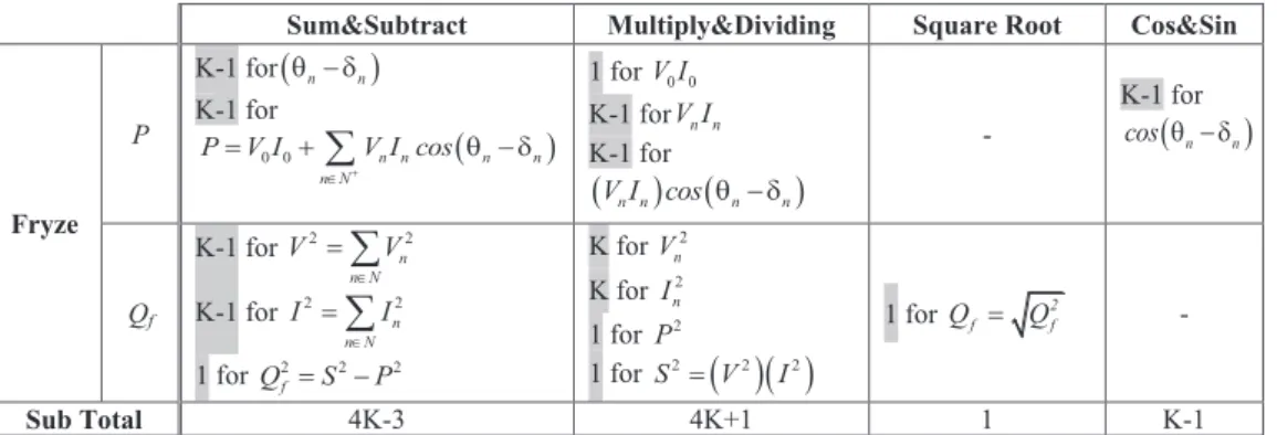
Table 2. The numbers of operations performed for the measurement of Fryze’s power resolution.
Table 3. The numbers of operations performed for the measurement of the power resolutions of Shepherd&Zakikhani and Sharon.
Sum&Subtract Multiply&Dividing Square Root Cos&Sin
Fryze P K-1 for(q - dn n) K-1 for ( ) 0 0 n n n n n N P V I V I cos + Î = +
å
q - d 1 for V I0 0 K-1 forV I n n K-1 for (V In n)cos(q - d n n) - K-1 for ( n n) cos q - d Qf K-1 for 2 2 n n N V V Î =å
K-1 for 2 2 n n N I I Î =å
1 for 2 2 2 f Q =S -P K for 2 n V K for 2 n I 1 for P 2 1 for S2=( )( )
V2 I2 1 for 2 f f Q = Q - Sub Total 4K-3 4K+1 1 K-1Sum&Subtract Multiply&Dividing Square Root Cos&Sin
Shepherd& Zakikhani 2 r I K-1 for ( ) 2 2 2 2 r 0 n n n n N I I I cos + Î = +
å
q -d K-1 for 2( ) n n cos q -d K-1 for( )
2(
2( ))
n n n I cos q -d - - 2 x I K-2 for ( ) 2 2 2 x n n n n N I I sin q d + Î =å
-K-1 for 2( ) n n sin q -d K-1 for( )
2(
2( ))
n n n I sin q -d - K-1 for ( n n) sinq - d 2 d I 1 for I2-Ir2 1 for 2(
2 2)
2 d r x I = I -I -I - - - Sr - 1 for( )( )
2 2 2 r r S = V I 1 for 2 r r S = S - Sx - 1 for( )( )
2 2 2 x x S = V I 1 for 2 x x S = S - Sd - 1 for( )( )
2 2 2 d d S = V I 1 for 2 d d S = S - Sharon Sc 1 for(
)
2 2 2 2 c x S = S -P -S - 1 for 2 c c S = S - Sub Total 2K 4K-1 4 K-1Metrol. Meas. Syst., Vol. XXI (2013), No. 2, pp. 263–274.
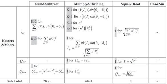
Table 4. The numbers of operations performed for the measurement of Kusters&Moore’s power resolution.
Table 5. The numbers of operations performed for the measurement of Czarnecki’s power resolution. Sum&Subtract Multiply&Dividing Square Root Cos&Sin
Kusters &Moore Iqc K-2 for ( ) n n n n n N nV I sin + Î q - d
å
K-2 for 2 2 n n N n V + Îå
K-1 for (V In n)(
sin(q - dn n))
K-1 for n V I sin(
n n (q - dn n))
K-1 for n 2 K-1 for( )( )
2 2 n n V 1 for ( ) 2 2 n n n n n N qc n n N nV I sin I n V + + Î Î q - d =å
å
1 for 2 2 n n N n V + Îå
-Qkus - 1 for Qkus=VIqc 1 for V= V2 -
Qkusr 1 for
(
)
2 2 2 2 kusr kus Q = S -P -Q 1 for 2 kus Q 1 for 2 kusr kusr Q = Q - Sub Total 2K-3 4K-1 3 -Sum&Subtract Multiply&Dividing Square Root Cos&Sin
Czarnecki 2 R I K-2 for ( ) 2 2 R n n n N I B V + Î =
å
K-1 for ( )(
)
( )
2 n n n n n n V I sin B V q - d = K-1 for ( )( )Bn Vn K-1 for (B Vn n)2 - - QCz - 1 for( )( )
2 2 2 Cz R Q = V I 1 for 2 Cz Cz Q = Q - Ds K for (Gn-Ge) K-1 for ( )2 2 2 s n e n n N I G G V Î =å
-1 for G0=I V0 0 K-1 for ( )(
)
( )
2 cos n n n n n n V I G V q - d = 1 for 2 e G =P V K for (Gn-Ge)2 K for ( )2 2 n e n G -G V 1 for 2( )( )
2 2 s s D = V I 1 for 2 s s D = D - Dh 1 for(
2 2)
2 Cz S -P -Q 1 for(
)
2 2 2 2 2 h Cz s D = S -P -Q -D - 1 for 2 h h D = D - Sub Total 3K-1 6K 3 -Brought to you by | Balikesir Üniversitesi Authenticated
In the tables, K and (K-1) are the numbers of voltage and current harmonics in N (natural numbers) and N+ (cardinal numbers), respectively. It can be seen from Table 2-Table 5 that for the simultaneous measurements of the power resolutions via their original expressions total numbers of sum&subtract, multiply&dividing, square root and cosines&sinus operations are 11K-7, 18K-1, 11 and 2K-2, respectively.
In the next section, a novel current decomposition will be provided for the simultaneous measurements of the power resolutions with reduced computational efforts.
3. Proposed method
To derive the expressions of the novel current decomposition, which can effectively be employed for the simultaneous measurements of the widely recognized power resolutions, firstly the active current component (ia) is calculated:
(
)
a e e 0 e n n n n N i =G v =G V + G 2V sin ω t+θ + Îå
(2) where 2(
)
2 0 0 cos e n n n n n n N n N G P V V I V I V + Î Î æ ö = =ç + q - d ÷è
å
øå
is the load’s equivalent conductance.In the second step, Kusters&Moore’s reactive current (iqc) is expressed:
1 2 2 qc e n n n n N i nB V sin t + Î æ ö = ç + - ÷ è ø
å
w q p (3)using the fundamental harmonic equivalent susceptance (Be1) defined as,
(
)
e1 + + + + n n n n n n N n N 2 2 2 2 n n n N n N nV I sin θ -δ nQ B = = n V n V Î Î Î Îå
å
å
å
(4)After writing active and Kusters&Moore’s reactive currents in terms of equivalent conductance and susceptance parameters, the current is separated into three components, namely; active, Kusters&Moore’s reactive and Kusters&Moore’s residual reactive (iqcr)
currents:
(
)
0 2 1 2 + e e n n n e n n n qcr n N n N i G V + 2G V sin ω t+θ nB V sin wt q p i + Î Î æ ö = + ç + - ÷+ è øå
å
(5)On the other hand, by means of the dc conductance (G0), nth harmonic conductance (Gn) and
nth harmonic susceptance (Bn);
(
)
(
)
n n n n n n n n 0 0 n n n 2 2 0 n n V I cos V I sin I G , Y G jB j V V V - -= = - = q d - q d (6) Brought to you by | Balikesir ÜniversitesiMetrol. Meas. Syst., Vol. XXI (2013), No. 2, pp. 263–274.
the current can be written as:
(
)
0 0 2 2 2 n n n n n n n n n N n N i G V G V sin wt q B V sin wt q p + + Î Î æ ö = + + + ç + - ÷ è øå
å
(7)By equating the right hand sides of (5) and (7), the residual reactive current of Kusters&Moore (iqcr) is found:
(
0)
0 2(
)
(
)
2(
1)
2 qcr e n e n n n n e n n n n N n N i G G V G G V sin wt q B nB V sin wt q p + + Î Î æ ö = - + - + + - ç + - ÷ è øå
å
(8) It is seen from (8) that iqcr is the sum of two current parts:Czarnecki’s scattered current;
(
)
(
)
(
)
s 0 e 0 n e n n n n N i G G V 2 G G V sin wt q + Î = - +å
- + (9)and a novel current component named as scattered susceptance current;
(
)
ss n e1 n n n n N i 2 B nB V sin t 2 p w q + Î æ ö = - ç + - ÷ è øå
(10)As a result, the current decomposition in the time domain is obtained:
a qc s ss
i= +i i + +i i (11)
Due to the orthogonality among four components of the proposed current decomposition, which was previously provided in [21], the rms value of total current can be written as:
(
)
2(
)
2(
)
2 2 2 2 2 2 1 1 2 2 2 2 2 a qc s ss e n e n n e n n e n n N n N n N n N I =I +I +I +I G V nB V G G V B nB V + + Î Î Î Î =å
+å
+å
- +å
- (12)In addition to the novel current decomposition given in (12), some cases should be considered to reduce computational efforts for the simultaneous measurements of the power resolutions:
· Distortion apparent power (Sd) of Shepherd&Zakikhani’s resolution and generated
harmonic power (Dh) of Czarnecki’s resolution are zero in practical systems due to the
fact that the voltage and current should contain the same harmonic orders [10]. · The reactive powers proposed by Shepherd&Zakikhani (Sx) and Czarnecki (QCz) give
the same results due to the equality given in (13):
(
)
2 2 2 2
n n n n n
B V =I sin q -d (13)
· The power resolutions proposed by Czarnecki and Sharon are identical for the practical systems due to the fact that the scattered and complementary power components give the same results [10].
Brought to you by | Balikesir Üniversitesi Authenticated
Finally, by considering above mentioned cases and novel current decomposition, it can be concluded that the product of the RMS voltage with
· active current (ia)’s RMS value gives the active or average power (P),
· the vector sum of RMS values of the current components apart from active current gives the reactive power defined by Fryze (Qf),
· the reactive current (iqc)’s RMS value gives the reactive power defined by
Kusters&Moore (Qkus),
· the vector sum of RMS values of the scattered (is) and scattered susceptance (iss)
currents gives the residual reactive power defined by Kusters&Moore (Qkusr),
· the scattered current’s RMS value gives the scattered power defined by Czarnecki (Ds) and the complementary power defined by Sharon (Sc),
· the vector sum of RMS values of the reactive and scattered susceptance currents gives the reactive powers defined by Czarnecki (QCz), Shepherd&Zakikhani and Sharon
(Sx),
· the vector sum of RMS values of the active and scattered currents gives the active apparent power defined by Shepherd&Zakikhani (Sr).
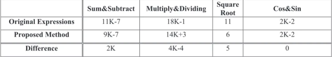
The numbers of the operations of the proposed current decomposition-based method, which is performed for the simultaneous measurements of the power resolutions, can be detailed as in Table 6. Thus, a comparison between the operation numbers of both methods is obtained in Table 7.
Table 7. Comparison between the operation numbers of both methods. Sum&Subtract Multiply&Dividing Square
Root Cos&Sin
Original Expressions 11K-7 18K-1 11 2K-2
Proposed Method 9K-7 14K+3 6 2K-2
Difference 2K 4K-4 5 0
It is seen from Table 7 that the numbers of cosinus and sinus calculations are the same in the both methods. On the other hand, the measurements based on the proposed method contain a smaller number of sum&subtract, multiply÷ and square root operations.
Thus, it can be concluded that the proposed method can be used for the simultaneous measurements of the powers with less computational efforts when compared to the original expressions of the power resolutions.
Due to the fact that the proposed power measurement method provides less computational complexity or requires a smaller number of operations, it can be clearly mentioned that the proposed one will present better performance than the original expressions from the point of view of measurement uncertainty.
Metrol. Meas. Syst., Vol. XXI (2013), No. 2, pp. 263–274.
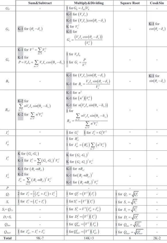
Table 6. The numbers of operations of the proposed method for simultaneous measurements of the power resolutions.
Sum&Subtract Multiply&Dividing Square Root Cos&Sin
G0 - 1 forG0=I V0 0 - - Gn K-1 for (qn-dn) K-1 for (V In n) K-1 for (V In n)cos(qn-dn) K for 2 n V K-1 for ( )
(
)
( )
n n n n n 2 n V I cos G V q -d = - K-1 for ( n n) cosq d -Ge K-1 for 2 2 n n N V V Î =å
K-1 for ( ) 0 0 n n n n n N P V I V I cos + Î = +å
q - d 1 for V I0 0 1 for e 2 P G V = - - Bn - K-1 for (V In n) (sinqn-dn) K-1 for n n ( n n) n 2 n V I sin B V q -d = - K-1 for ( n n) sinq d -Be1 K-2 for ( ) n n n n n N nV I sin + Î q - då
K-2 for 2 2 n n N n V + Îå
K-1 for 2 n K-1 for( )( )
2 2 n n V K-1 for n V I sin(
n n (q - dn n))
1 for ( ) 1 2 2 n n n n n N e n n N nV I sin B n V + + Î Î q - d =å
å
- - 2 a I - 1 for 2 e G 1 for 2 2 2 a e I =G V - - 2 qc I - 1 for 2 1 e B 1 for 2( ) (
2 2 2)
1 qc e n n N I B n V + Î =å
- - 2 s I K for (G -Gn e) K-1 for 2 ( )2 2 s n e n n N I G -G V Î =å
K for (G -Gn e)2 K for ( )2 2 n e n G -G V - - 2 ss I K-1 for (B -nBn e1) K-2 for ( ) 2 + 2 2 ss n e1 n n N I B -nB V Î =å
K-1 for nBe1 K-1 for(B -nBn e1)2 K-1 for ( )2 2 n e1 n B -nB V - - P - - - - Qf 2 for(
)
2 2 2 2 f qc ss s I =éëI +I +I ùû 1 for 2( )( )
2 2 f f Q = V I 1 for 2 f f Q = Q - Sr 1 for(
)
2 2 2 r a s I = I +I 1 for 2( )( )
2 2 r r S = V I 1 for 2 r r S = S - Sx= QCz - 1 for(
)
2 2 2 2 x qc ss S =V I +I 1 for Sx= S2x - Ds=Sc - 1 for( )( )
2 2 2 s s D = V I 1 for 2 s s D = D - Qkus - 1 for( )( )
2 2 2 kus qc Q = V I 1 for 2 kus kus Q = Q - Qkusr 1 for 2 2 2 qcr s ss I =I +I 1 for 2( )( )
2 2 kusr qcr Q = V I 1 for 2 kusr kusr Q = Q - Total 9K-7 14K+3 6 2K-2Brought to you by | Balikesir Üniversitesi Authenticated
4. Demonstration of a PC-based power meter developed according to the proposed method
For the proposed power measurement method, a computer (PC)-based power meter is developed by using LabVIEW programme. The LabVIEW block diagram, which runs on PC, is given in Fig. 1. This figure shows that the LabVIEW block diagram has a compact frame, which could be divided into two main parts related with the computations of the voltage and current harmonics and the measurement of the powers.
Fig. 1. Designed LabVIEW block diagram for the simultaneous measurements of the power resolutions according to the proposed method.
4.1. Demonstration system
A picture of the system, which is used for demonstration of the developed PC-based power meter, is given in Fig. 2. The demonstration system consists of a PC, a programmable power supply, which is used for generation of a non-sinusoidal supply voltage, a data acquisition card and a load (RL impedance bank controlled by a dimmer circuit).
Fig. 2. Picture of the demonstration system.
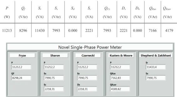
4.2. Measurement results
A randomly generated non-sinusoidal supply voltage and non-sinusoidal load current, which are used for the demonstration, have total harmonic distortion values measured as 15% and 25%, respectively. For the demonstration voltage and current, the power components’ values are calculated by using their original expressions (Table 8). Table 8 shows that Sd and
Dh are zero for the demonstration case. It is also seen that Sx is equal to QCz, and Sc is equal to
Metrol. Meas. Syst., Vol. XXI (2013), No. 2, pp. 263–274.
Ds. For the same case, Fig. 3 shows the screen of the PC-based power meter, which is used for
simultaneous measurements of the power resolutions according to the proposed method. One can see from Table 8 and Fig. 3 that the results of both methods are almost the same.
Table 8. For the demonstration case, the power components’ values calculated by using the original expressions of the power resolutions.
P (W) Qf (VAr) Sr (VA) Sx (VAr) Sd (VA) Sc (VA) QCz (VAr) Ds (VA) Dh (VA) QKus (VAr) QKusr (VAr) 11213 8296 11430 7993 0.000 2221 7993 2221 0.000 7166 4179
Fig. 3. Screen of the PC-based power meter for the demonstration case.
5. Conclusion
In this paper, a method is proposed to measure the widely recognized power resolutions with computational efficiency. It is mainly based on the division of the load current into orthogonal components, which are related to the equivalent conductance and susceptance of the load.
The results of the complexity analysis point out that the proposed method has a significant advantage in terms of computational efficiency for the simultaneous measurements of the powers when compared with the original expressions of the power resolutions. In addition to that, for the proposed method a PC-based power meter is developed using the LabVIEW programme. Its measurement results for a demonstration case show that developed PC-based meter can effectively be employed for simultaneous power measurements in non-sinusoidal conditions.
Acknowledgements
This work was supported by the Scientific and Technological Research Council of Turkey (TUBITAK) under project number 110E113.
References
[1] Budeanu, C. I. (1927). Reactive and Fictitious Powers. Bucuresti: Romanian Nat. Inst.
[2] Fryze, S. (1932). Wirk-, Blind, und Scheinleistung in Elektrischen Stromkreisen Mit Nichtsinusoidalformigem Verlauf von Strom und Spannung. Elektrotechnische Zeitschrift, 53 (25), 596-599.
Brought to you by | Balikesir Üniversitesi Authenticated
[3] Shepherd, W., Zakikhani, P. (1973). Power Factor Correction in Nonsinusoidal Systems by the Use of Capacitance. J. of Phys. D: Appl. Phys., 6, 1850-1861.
[4] Sharon, D. (1973). Reactive Power Definition and Power-Factor Improvement in Nonlinear Systems. Proc. Inst. Elec. Eng., 120, 704-706.
[5] Kusters, N. L., Moore, W. J. M. (1980). On the Definition of Reactive Power under Nonsinusoidal Conditions. IEEE Trans. on Power Appar. and Syst., 99 (5), 1845-1854.
[6] Czarnecki, L. S. (1993). Physical Reasons of Currents RMS Value Increase in Power Systems with Nonsinusoidal Voltage. IEEE Trans. on Power Deliv., 8 (1), 437-447.
[7] IEEE Std. 1459-2010 (2010). IEEE Standard Definitions for the Measurement of Electric Power Quantities under Sinusoidal, Non-sinusoidal, Balanced or Unbalanced Conditions.
[8] Emanuel, A. E. (1990). Powers in Nonsinusoidal Situations a Review of Definitions and Physical Meaning. IEEE Trans. on Power Deliv., 5 (3), 1377-1389.
[9] Czarnecki, L. S. (1990). Comparison of Power Definitions for Circuits with Nonsinusoidal Waveforms. IEEE Tutorial Course 90EH0327-7-PWR, 43-50.
[10] Balci, M. E., Hocaoglu, M. H. (2008). Quantitative Comparison of Power Decompositions. Electr. Power Syst. Res., 78 (3), 318-329.
[11] Kosobudzki, G., Nawrocki, Z., Nowak, J. (2005). Measure of Electric Reactive Power. Metrol. Meas. Syst., 12 (5), 131-150.
[12] Cataliotti, A., Cosentino, V. (2009). A Single-Point Approach Based on IEEE 1459-2000 for the Identification of Detection of Prevailing Harmonic Sources in Distorted Three Phase Power Systems. Metrol. Meas. Syst., 16 (2), 209-219.
[13] Balci, M. E., Karacasu, O., Hocaoglu, M. H. (2009). A Detection Method for Harmonic Producing Loads. In Proc. of Eleco 2009 Conference, Bursa, Turkey, I-149- I-153.
[14] Gherasim, C., Van den Keybus, J., Driesen, J., Belmans, R. (2004). DSP Implementation of Power Measurements According to the IEEE Trial-Use Standard 1459. IEEE Trans. on Instrum. Meas., 53 (4), 1086–1092.
[15] Moreira, A. C., Deckmann, S. M., Marafao, F. P., De Lima, E. G., Bini, M. A. (2005). Virtual Instrumentation Applied to the Implementation of IEEE-STD 1459-2000 Power Definitions. In Proc. of IEEE PESC 2005, Recife, Brazil, 1712-1718.
[16] Orfanos, C. N., Topalis, F. V. (2005). Single-phase Virtual Power and Energy Analyzer in Compliance with IEEE Std 1459–2000 for Harmonic Measurements on Discharge Lamps. In Proc. of IEEE Powertech 2005, St. Petersburg, Russia, 1-6.
[17] Cataliotti, A., Cosentino, V., Nuccio, S. (2008). A Virtual Instrument for the Measurement of IEEE Std. 1459-2000 Power Quantities. IEEE Trans. on Instrum. Meas., 57 (1), 85–94.
[18] D’Apice, B., Landi, C., Pelvio, A., Rignano, N. (2007). A Multi- DSP Based Instrument for Real-Time Energy and PQ Measurements. Metrol. Meas. Syst., 14 (4), 495-506.
[19] Labview8.6 programme. Data sheet for Labview. http://www.ni.com/ (Sept. 2008).
[20] Balci, M. E., Hocaoglu, M. H. (2010). A Current resolution for Fast Measurement of Power Resolutions in Non Sinusoidal Single Phase Systems. In Proc. of IEEE ICHQP 2010, Bergamo, Italy, 1-6.
[21] Balci, M. E., Hocaoglu, M. H. (2006). New Power Decomposition for Sinusoidal and Nonsinusoidal Conditions. In Proc. of IEEE ICHQP 2006, Cascais, Portugal. CD-ROM.