Photonic Crystal based Spatial Filtering
E. Colak*1, A. O. Cakmak1, A. E. Serebryannikov1,2, and E. Ozbay11Department of Physics, Department of Electrical and Electronics Engineering, Nanotechnology Research Center—NANOTAM,
Bilkent University, 06800 Ankara, Turkey.
2Technische Universitaet Hamburg-Harburg, D-21071 Hamburg, Germany.
* Corresponding author ([email protected])
Abstract: Two dimensional Photonic Crystal structure is used to achieve spatial filtering. The structure
provides bandstop filtering in the incident angle range of 18° to 38°. The transmission is close to unity outside of this range.
1. Introduction
Spatial filters are used for investigation of spatial spectrum, radar data processing, aerial imaging, the detection of extrasolar planets, as well as in biomedical applications [1, 2]. Such spatial filters can be implemented via anisotropic media [1],resonant grating systems [3,4],interference patterns [5],multilayer stacks combined with a prism [2],metallic grids over a ground plane [6],and slabs of photonic crystal (PC) with defects [7]. Due to different signs of the elements of the permittivity and permeability tensors, ranges of transmittance T<1 and reflectance R=1 have been obtained using the anti-cutoff media [1]. However, obtaining wide angle domain ranges of total transmission is still a subject of research.
In [8], it is shown that wide adjacent ranges of variation of θ>0 with T
»
1 and R=1, and with a steep switching between them can be realized using two dimensional, square-lattice, dielectric PCs with proper topologies of isofrequency contours (IFCs). Here, the experimental setup and both the simulation and experimental results will be given to prove the idea of total transmission and reflection (T»
0) for illumination at certain incident angles.2. Analysis
High-pass or bandpass filtering at θ=const can be achieved if IFCs are localized around either the M point of the first Brillouin zone (FBZ) if the PC interfaces are parallel to the Γ-X direction (case (a)), or the X point if they are parallel to the Γ-M direction (case (b)). A bandstop or dual bandpass filter at ψ=const, that has a passband including ψ=0 is achieved for the case where IFCs are localized around the M point while the interfaces are parallel to the Γ-M direction (case (c)), or when the IFCs localized around the X point coexist with those around the M point while the interfaces are parallel to the Γ-X direction (case (d)). Considering several flat IFC cases, working with PCs with Γ -X as the excitation interface and a similar IFC shape as in Fig. (1d), a passband with ψb>20° can be obtained whose details are described in [8].
FIG. 1. Examples of IFCs for a square-lattice PC which are given in [8]: arrows show the direction of the incident wave at ψ=0, dashed lines indicate the orientation of the interfaces, dotted linen indicate FBZ boundaries.
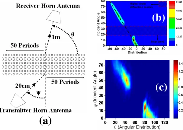
Experimental work setup is given in Fig. 2(a). For N= 8 (number of layers), ψ which is the incident angle is varied from 0o to 80o. The two dimensional Photonic Crystal (PC) consists of an 8x101 array of
735
ThO4 11.30 - 11.45
dielectric (alumina) rods. The rods have a diameter of 3.15mm and their permittivity is 9.61. The length of the rods is 15.4cm. The lattice constant of the PC is 7mm. The distance from the transmitter to PC is 20cm whereas the distance from the PC to the receiver antenna is 1m. In Figure 2(b), the simulation results which are obtained by Finite Difference Time Domain (FDTD) Method reveal that, the Transmisson falls to 0 (T
»
0) (i.e., bandgap, bandstop region) between incident angles of 18o and 38o. The transmission experiment is carried out at 21.41GHz by employing a pair of horn antennas. A corresponding bandgap also exists as seen in the experimental result which is given in Fig. 2(c).
Fig. 2. (a) Experimental setup for spatial filtering, (b)Simulation of the transmission obtained by FDTD method, (c) Experimental result obtained at 21.41GHz.
Conclusion
Employing two dimensional Photonic Crystal structure spatial (Bandstop) filtering is achieved. In the simulation results which are carried out with the FDTD Method, it is seen that the Transmission is prohibited for the incident angle range of 18° to 38°. Experimental work performed at 21.41GHz verifies the simulation results. The transmission is close to unity outside of the bandgap.
References
1. D. Schurig and D. R. Smith, Appl. Phys. Lett. 82, 2215 (2003).
2. I. Moreno, J. J. Araiza, and M. Avedano-Alejo, Opt. Lett. 30, 914 (2005). 3. R. Rabady and I. Avrutsky, Opt. Lett. 29, 605 (2004).
4. A. Sentenac and A.-L. Fehrembach, J. Opt. Soc. Am. A 22, 475 (2005). 5. L. Dettwiller and P. Chavel, J. Opt. Soc. Am. A 1, 18 (1984). 6. O. F. Siddiqui and G. Eleftheriades, J. Appl. Phys. 99, 083102 (2006). 7. A. E. Serebryannikov and T. Magath, J. Opt. Soc. Am. B 25, 286 (2008).
8. A. E. Serebryannikov, A. Y. Petrov, and Ekmel Ozbay, “Toward Photonic Crystal Based Spatial Filters with Wide Angle Ranges of Total Transmission” Applied Physics Letters 94, 181101, (2009).
![FIG. 1. Examples of IFCs for a square-lattice PC which are given in [8]: arrows show the direction of the incident wave at ψ=0, dashed lines indicate the orientation of the interfaces, dotted linen indicate FBZ boundaries.](https://thumb-eu.123doks.com/thumbv2/9libnet/5948147.124005/1.918.364.552.797.981/examples-direction-incident-indicate-orientation-interfaces-indicate-boundaries.webp)