Şu le T aş lı Pe kt aş op en h ou se in te rn at io na l V ol .3 9 N o. 1, M ar ch 2 01 4. T he L ay er ed D ep en de nc y St ru ct ur e M at rix fo r M an ag in g C ol la bo ra tiv e D es ig n Pr oc es se s. I NTRO D UC TI O N
The two foremost groups of building professionals are architects and structural engineers. The former aim, mainly, at providing functional, efficient, and aesthetic spatial environments, and are thus con-cerned primarily with space and elements related to it such as spatial organization, spatial divisions, environmental behavior of spaces, etc.; they use concepts such as “spatial flow”, “hierarchy of spaces”, and “environmental comfort”. Structural engineers, on the other hand, aim at providing strength and stability by means of structural ele-ments that resist imposed loads or transmit internal forces, and are thus concerned with structural com-ponents such as beams, columns, and shear walls, while using concepts such as “gravitational/lateral force”, “support”, and “deformation”.
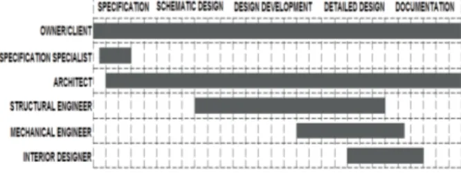
What's more, in any building project which comprises a design process, these two groups, among the different professionals associated with such a process, are those who work together for the longest period of time (Figure 1).
This collaboration between architects and structural engineers is characterized by iteration and rework, entailing an intense flow of information among the different participants. However, not many studies have been done to either understand the nature of this flow, or find ways of manipulating it (Eastman, 1999: 347). As a result, the steps and stages of the decision-making process that leads to specific building design configurations remain invis-ible. This is probably also due to the fact that build-ing design is a very difficult process to manage. It
involves thousands of decisions with numerous interdependencies in a highly uncertain environ-ment. It moreover entails a large staff, and each group of experts has a distinct and different profes-sional background.
It is also widely known that a considerable amount of building defects result from decisions made by these two groups during the design process. Although the increasing complexity of buildings and the existence of a very competitive market-place have been forcing design profession-als to improve their performances in terms of time and quality, many of their projects still do not con-tain any systematic design planning. This is due to the common misconception of designers that design, being a creative process, cannot be planned effectively. And even when planning is done, it is carried out in an intuitive manner based solely on discipline-specific programs, although, to be effective, collaboration in design necessitates planning the flow of interdisciplinary information. However, compared to production management in construction, to which much scholarly attention has been given, relatively little research has been done
Şule Taşlı Pektaş
Abstract
Effective collaboration and knowledge management are the major contributors of success in the construction industry. Although a huge amount of interdisciplinary knowledge is exchanged in building design processes, there is a lack of tools for representing information flows. Therefore, this paper focuses on the collaboration between architects and struc-tural engineers and introduces an innovative matrix-based tool named “The Layered Dependency Structure Matrix” for modeling and managing the discipline-specific and collaborative design activities. The proposed method is compared with the conventional techniques used in the industry and its application is demonstrated in a beam design example. Keywords: Collaborative Design, Design Process, Disciplinary Domains, Process Modeling, Dependency Structure Matrix, Design Structure Matrix, Complexity Management.
THE LAYERED DEPENDENCY STRUCTURE MATRIX FOR
MANAGING COLLABORATIVE DESIGN PROCESSES.
Figure 1.A generalized schema of building design process-es and organizations(adapted from Kalay et al., 1998: 178)
op en h ou se in te rn at io na l V ol .3 9 N o. 1, M ar ch 2 01 4. T he L ay er ed D ep en de nc y St ru ct ur e M at rix fo r M an ag in g C ol la bo ra tiv e D es ig n Pr oc es se s. Şu le T aş lı Pe kt aş
on the management of the design process (Formoso et al., 1998), as is the case for the flow of information during the design process, as noted above.
This paper is based on the premise that it is useful to develop quantifiable models of the build-ing design process within a systematic approach developed to understand complex phenomena related to design (Pektaş, 2007, 2010; Pektaş and Özgüç, 2011). Although "modeling" has limitations arising from the reduction of a complex situation to a (simplified, yet) more structured form, it does have valuable merits, as it allows one to learn about a process, and suggests ways by which the process may be controlled. Starting from this viewpoint, this paper proposes the use of a layered dependency structure matrix (DSM) as a system analysis and scheduling tool for building design. First, process models of design are briefly reviewed, and then the dependency structure matrix method is explained in detail. Finally, an innovative DSM-based tool, which represents the collaboration processes of architects and structural engineers, is introduced. The utilization of the tool is demonstrated through a beam design example.
PRO CE SS MOD E LS O F D ESI GN
There is a distinct stream of modeling research work on design methodology that focuses on the descriptive methodological and philosophical frameworks of the design process. It includes Hubka's Principles of Engineering Design (this trans-lation into English 1982); Pahl and Beitz's Engineering Design (this translation into English 1984); and Cross's Engineering Design Methods: Strategies for Product Design (1989), to name a few. In the models put forth by these works, the
design process is described in terms of generic phases in an either linear or cyclic manner. Another characteristic common to all these works is their representing the process at high levels, and giving very little information at lower levels. On the other hand, in this paper, the focus is on quantitative and graphical models that are capable of representing design processes in detail with most of the com-plexity involved.
In the construction industry, chart-based scheduling is still the most widely used process modeling method. This type of modeling compris-es the milcompris-estone chart and the bar chart. Charts are easy to prepare and use, but their application is limited to short design projects with few partici-pants, since they cannot represent any design-relat-ed information beyond activity durations.
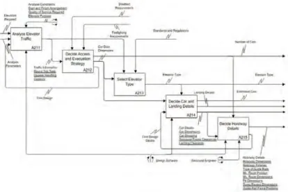
Network models can overcome some of the drawbacks of chart-based methods by incorpo-rating activity relationships. Such models are based on the premise that once decomposed, the design process may be described as an interconnected network of design tasks which may be illustrated on a directed graph. The Project Evaluation and Review Technique (PERT), the Critical Path Method (CPM) (Galloway, 2006), and the Integrated DEFinition Language (IDEF) (Karhu, 2000) are examples of models based on digraphs which are used in the construction industry (Figure 2). However, there are several limitations in these
mod-eling methods, such as the following:
1. They lack the ability to model feedback and iteration in the projects, so they cannot model projects as a dynamic decision process; 2. They have a top-down approach and do not
support detailed analyses which are required due to the complexity of design processes;
3. They take only the document
pro-ducing activities into consideration for modeling, in spite of the fact that an important amount of information flows by informal communication in design processes;
4. They can be time-consuming to
prepare, and difficult to read and update. As a result, they are often more useful in the construction phase than the design phase of the building process;
5. They suffer from size limitations,
since they tend to grow rapidly for a large number of tasks, and the visual inspection of the information structure becomes very complex and also misleading.
Figure 2.An example network diagram: elevator design process model in IDEF0 notation (researched and developed by the author).
Şu le T aş lı Pe kt aş op en h ou se in te rn at io na l V ol .3 9 N o. 1, M ar ch 2 01 4. T he L ay er ed D ep en de nc y St ru ct ur e M at rix fo r M an ag in g C ol la bo ra tiv e D es ig n Pr oc es se s.
Thus, it is clear that there is a need for new process modeling methods in building design which are both compact and capable of represent-ing iterations, dependencies, critical activities, and other components of design complexity.
T H E D E P E ND E N C Y S T R U C T U R E
MA TR I X METH O D
An alternative method for the design process, namely the dependency structure matrix method, has its roots in the 1960s, when several efforts were devoted to understanding systems. Donald Steward first coined the term “Design Structure Matrix” in 1981 (Steward, 1981: 71). The design structure matrix method gained credibility as a result of sev-eral studies at the Massachusetts Institute of Technology (MIT) in the 1990’s. In recent years, research devoted to this topic has expanded to include many new areas, and a more general term, “Dependency Structure Matrix” (DSM), has come to be used.
A dependency structure matrix is a matrix representation of a system or a project. The rows and columns of the symmetric matrix consist of a list of all elements of the system; while matrix elements represent the corresponding dependency patterns. In general, there are two types of process DSMs, namely activity (task)-based and parameter-based (Browning, 2001). The process DSM methods assume that each task (or a decision about a para-meter) can be modeled as an information process-ing activity, usprocess-ing and creatprocess-ing information. The output information from one activity becomes the input information to another activity. Activities are indicated in the rows and columns, in roughly a chronological order. Matrix elements indicate the existence and direction of information flow from one activity to another. Reading across a row, a dependency mark reveals the flows to that element from the column activities. Reading down a column reveals the output information flows from the activ-ity represented by that column to other activities. Thus, the marks to the right of the diagonal in a sin-gle row reveal a feedback from a later activity to an earlier one that causes iteration in the design process. By re-arranging the position of activities, unintentional iterations can be avoided and an optimum sequence may be obtained (Figure 3).
The construction of a DSM requires exten-sive knowledge of the system to be modeled. Besides the formal knowledge manifested in design documents, the DSM method aims also to capture informal knowledge held by the professionals. Therefore, in the initial stages, it may be difficult to produce a useful DSM. However, once an initial
DSM model is built, it can serve as a platform for continued organizational learning and process improvement. The DSM method is advantageous compared to other process modeling methods, because it provides a compact, visual, and analyti-cally advantageous format even for complex tasks. Although other process modeling techniques are also useful for scheduling activities, they do not enable an analysis of the total information structure processed in the system.
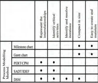
A comparison of DSM with the other process modeling methods used by the construction industry is given on Table 1.
A recent book edited by Eppinger and Browning (2012) demonstrated that DSM applica-tions include a wide range of industries such as automotive, aerospace, electronics, building, and pharmaceutical. Krishnan (1993) has worked on sequencing and overlapping activities in product development via DSM, to improve design process-es in the automotive and electronics industriprocess-es. Browning (1998) has applied DSM techniques in developing lean design strategies for the aerospace Figure 3.Three configurations that characterize a sys-tem in DSM analysis.
Table 1.A Comparison of the DSM Method with the other Process Modeling Methods.
op en h ou se in te rn at io na l V ol .3 9 N o. 1, M ar ch 2 01 4. T he L ay er ed D ep en de nc y St ru ct ur e M at rix fo r M an ag in g C ol la bo ra tiv e D es ig n Pr oc es se s. Şu le T aş lı Pe kt aş
industry. Rogers and Salas (1999) have built a web-based DSM system at NASA (the US National Aeronautics and Space Administration) for sequencing and monitoring design processes. Hameri, Nihtila and Rehn (1999) have studied doc-ument interdependencies on the design phase of one-of-a kind delivery processes. English, Bloebaum and Mille (2001) have developed a DSM-based method for quantifying the strength of couplings in multidisciplinary design processes in mechanical and aerospace engineering.
Applications of DSM in the construction industry have mostly utilized high-level activity-based DSM. The method has been applied in building research at VTT (Valtion Teknillinen Tutkimuskeskus - Technical Research Center of Finland) and at Loughborough University. At VTT, Huovila and Seren (1998) have studied the applic-ability of DSM in understanding customer needs and in planning the building design process. The research team at Loughborough University has developed a DSM-based design planning tech-nique called Analytical Design Planning Techtech-nique (ADePT) (Austin et al., 2002). These studies have demonstrated that activity-based DSM is a useful project management tool. However, analyses of finer granularity—at parameter level— have been needed to exploit the capabilities of the method for visualizing and managing complexity in design. A parameter-based DSM represents the information flows between parameter decisions (the lowest level activities) and allows bottom-up analysis. Black et al. (1990) have applied a parameter-based DSM to automobile brake system design. The method has also been used in planning software develop-ment for airplane design at Boeing Company (Browning, 1998). The parameter-based DSM method was introduced to building design by Pektaş and Pultar (2006) and recognized interna-tionally by the scholars in the field. This paper fur-ther elaborates the parameter-based DSM method in order to represent information ownership in inter-disciplinary design. The following section describes the proposed method.
PRO CE SS MO DE LI NG FO R BU I LD ING D ESI GN USI NG TH E L AYE RE D D SM Browning (1998) explains that DSMs are especially useful when several participants must coordinate actions and/or information, because they provide a medium whereby the groups can visualize and explore how they must function together to achieve overall goals. Such is the condition in the collabo-ration of architects and structural engineers in building design. However, in a conventional DSM,
a mark denotes merely existence of a dependency or an information flow. Information ownership (who produces a particular piece of information) is not visible. In interdisciplinary design tasks (like most of the activities of architects and structural engineers) decisions on design parameters are highly coupled because information ownership is often shared. This paper proposes that collaborative design processes can be described with a layered DSM with each layer showing processes of a design pro-fessional. The bottom layer is called the “Collaborative Process DSM” and it results from the superposition of discipline-specific dependencies (Figure 6).
A layered DSM may provide insights into the following issues:
1. Information ownership
2. The optimum sequence of parameter decision points
3. Critical parameters that cause large iteration cycles
4. Design decisions that can be made concurren ly (parallel, at the same time)
5. Schedule of assumptions to be made in the process.
Of course, there are many parameters involved in design processes. Therefore, to capture and manage all describing parameters in building design may be unrealistic and not necessary. A selection can be made depending on the pur-pose of the parameter deployment. If the num-ber of considered parameters is based on the critical tasks, the number of parameters to be captured reduces considerably. Even such a small-scale model is useful for the following reasons:
1. Sharing a DSM opens the process to its partic-ipants and facilitates a common understanding of the process. This is especially useful for col-laborative projects in which participants may have difficulty in understanding how the whole system works. Designers may not be aware of what information they hold and what informa-tion they owe to others. DSM can be an effi-cient learning tool to discover previously unknown patterns of design and organization-al architecture.
2. For many processes it is very difficult to estimate the magnitude of change and the effort required without the knowledge of the existing state. The recognition of problems in existing processes is important in order to avoid repeat-ing the problems in the new process.
Şu le T aş lı Pe kt aş op en h ou se in te rn at io na l V ol .3 9 N o. 1, M ar ch 2 01 4. T he L ay er ed D ep en de nc y St ru ct ur e M at rix fo r M an ag in g C ol la bo ra tiv e D es ig n Pr oc es se s.
3. In building design, several assumptions are made when related information is not avail-able. These assumptions are reviewed at some point in the process in order to validate them. What assumptions have been made and when they are to be reviewed are critical for process success. DSM makes these assumptions explic-it. It identifies when assumptions should be made and how they affect the overall process. 4. Explicit definition of parameters and
character-istics of information flows between them is also helpful for the development of parametric mod-eling systems which have attracted much atten-tion in recent years.
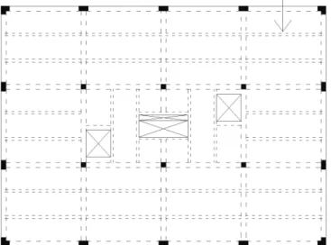
A n Ex ample DSM f or Be am Desig n The application of the layered DSM to design processes of architects and structural engineers may be best explained by an example. The exam-ple building presented here has been adapted from Parker and Ambrose's Simplified Engineering for Architects and Builders (1993). The building is a three-story office building and has a cast-in-place slab and beam system of reinforced concrete. Concrete columns provide support for the spanning structure. Figure 4 shows the structural framing plan for the reinforced concrete structure of the building. The basic floor-framing system consists of a series of beams that support a continuous, one-way span-ning slab and are supported by column-line girders or directly by the columns. The beam shown by an arrow in Figure 4 carries a narrow strip of the slab as a uniformly distributed loading.
Parameter-based DSMs have been devel-oped for the design of this beam as explained below. DSM operations were then performed to optimize the sequence of parameter decision
points, to identify iterative cycles, and to decide on when assumptions should be made. A Visual Basic software program initially developed at the MIT and enhanced by the author was used in the analysis. Building the DSM
Building of any type of DSM consists of three steps in general:
1. Determine the list of tasks or parameters 2. Build a DSM listing the system elements as row
and column labels in the same order 3. Determine inputs and outputs.
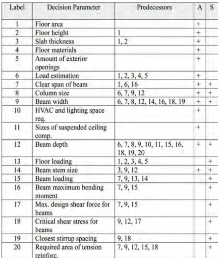
Within this framework, a parameter is defined as a physical property whose value deter-mines a characteristic or behavior of a system com-ponent. Such parameters include sizes, quantities, loads, and material resistance. For the beam design example, twenty basic parameters were identified and listed in the matrix in a roughly chronological order. Floor area, floor height, floor materials, and amount of exterior window surface were considered as input parameters and it is assumed that their values remain constant during the beam design process. The value of the slab thickness is based on assumed minimum require-ments for fire protection. The clear span would not require this thickness based on limiting bending or shear conditions or recommendations for deflection control. These five parameters as well as initial val-ues of beam width, column size, clear span of beam, and beam depth are assumed to be deter-mined by the architect. Other parameters were in the domain of structural design and their values affected the sizes designed by the architect.
A precedence analysis helps in identifying the interactions between system elements before entering them in the matrix. The precedence relations of our example are shown in Table 2.
The DSM corresponding to this table is shown in Figure 5. Here, the letters A, B, and S denote an information flow from the column parameter to the row parameter. The letters used discriminate the information ownership with "A" indicating architect, "S" structural engineer, and "B" both, producing information for a specific parameter deci-sion.
In fact, the matrix shown in Figure 5 can be thought of as a two-dimensional projective superposition of two overlapping discipline-specific matrices as depicted in Figure 6. Each of these DSMs represents the Figure 4.The structural framing plan of the example building.
op en h ou se in te rn at io na l V ol .3 9 N o. 1, M ar ch 2 01 4. T he L ay er ed D ep en de nc y St ru ct ur e M at rix fo r M an ag in g C ol la bo ra tiv e D es ig n Pr oc es se s. Şu le T aş lı Pe kt aş
Figure 5.The parameter-based DSM for the collaborative beam design example.
Table 2.The Precedence Relations for the Beam Design Example. The column A includes those parameters in the architect’s domain and S those in the structural engineer’s domain.
Şu le T aş lı Pe kt aş op en h ou se in te rn at io na l V ol .3 9 N o. 1, M ar ch 2 01 4. T he L ay er ed D ep en de nc y St ru ct ur e M at rix fo r M an ag in g C ol la bo ra tiv e D es ig n Pr oc es se s.
view of the design problem from the point of the corresponding discipline.
Pa rt ition ing t he DSM
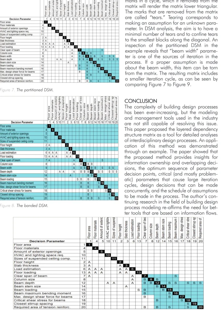
Partitioning is the process of re-ordering the DSM rows and columns so that the resulting matrix does not contain iterations. This means that the DSM is transformed into a lower triangular form. For com-plex processes, it is often impossible to obtain a lower triangular form DSM by partitioning. In this case, the aim is to cluster the feedback marks in a block about the diagonal of the DSM so that fewer system elements are involved in the iteration cycle. The partitioned DSM of our example is shown in Figure 7. It contains three coupled blocks affecting eleven parameter decisions.
B an din g th e DSM
In the banding procedure, alternating light and dark bands are added to the matrix to show inde-pendent parameter decision points. The decision process for the parameters belonging to the same band can be conducted concurrently, i.e. in paral-lel. In a DSM, it is desirable to have as few bands as possible. As shown in Figure 8, there are thirteen bands in the partitioned matrix. The first band con-sists of five independent parameters, which are the inputs to beam design process. The large amount of bands denotes the highly interdependent nature of design processes of architects and structural engineers.
Te ar ing t he DSM
Tearing is the process of choosing those feedback Figure 6.DSM as superposition of discipline-specific dependencies.
op en h ou se in te rn at io na l V ol .3 9 N o. 1, M ar ch 2 01 4. T he L ay er ed D ep en de nc y St ru ct ur e M at rix fo r M an ag in g C ol la bo ra tiv e D es ig n Pr oc es se s. Şu le T aş lı Pe kt aş
marks in a cycle, which if removed from the matrix will render the matrix lower triangular. The marks that are removed from the matrix are called “tears.” Tearing corresponds to making an assumption for an unknown para-meter. In DSM analysis, the aim is to have a minimal number of tears and to confine tears to the smallest blocks along the diagonal. An inspection of the partitioned DSM in the example reveals that “beam width” parame-ter is one of the sources of iparame-teration in the process. If a proper assumption is made about the beam width, this item can be torn from the matrix. The resulting matrix includes a smaller iteration cycle, as can be seen by comparing Figure 7 to Figure 9.
CONCLUSION
The complexity of building design processes has been ever-increasing, but the modeling and management tools used in the industry are not still capable of resolving this issue. This paper proposed the layered dependency structure matrix as a tool for detailed analyses of interdisciplinary design processes. An appli-cation of this method was demonstrated through an example. The paper showed that the proposed method provides insights for information ownership and overlapping deci-sions, the optimum sequence of parameter decision points, critical (and mostly problem-atic) parameters that cause large iteration cycles, design decisions that can be made concurrently, and the schedule of assumptions to be made in the process. The author’s con-tinuing research in the field of building design process modeling re-affirms the need for bet-ter tools that are based on information flows. Figure 7.The partitioned DSM.
Figure 8.The banded DSM.
Şu le T aş lı Pe kt aş op en h ou se in te rn at io na l V ol .3 9 N o. 1, M ar ch 2 01 4. T he L ay er ed D ep en de nc y St ru ct ur e M at rix fo r M an ag in g C ol la bo ra tiv e D es ig n Pr oc es se s.
The author hopes that this new method would form the basis of useful tools for the collaborative processes of the construction industry.
Author’s Note: An earlier version of this paper was presented in Buildings Ahoy: A Festschrift in Honor of Mustafa Pultar (limited edition of 75 copies).
RE FE RE NCE S
AUSTIN, S., NEWTON, A., STEELE, J. and WASKETT, P. 2002, Modeling and managing project complexity, International Journal of Project Management, 20:3, 191-198.
BLACK, T. A., FINE, C. H. and SACHS, E. M. 1990, A Method for Systems Design Using Precedence Relationships: An Application to Automotive Brake Systems, M.I.T. Sloan School of Management Working Papers no. 3208, Cambridge, MA: Sloan School of Management, MIT.
BROWNING, T. R. 1998, Modeling and Analyzing Cost, Schedule, and Performance in Complex System Product Development, Unpublished PhD. dissertation, Technology, Management and Policy Program, Massachusetts Institute of Technology.
BROWNING, T. R. 2001, Applying the design structure matrix to system decomposition and integration problems: a review and new directions, IEEE Transactions on Engineering Management, 48:3, 292-306.
CROSS, N. 1989, Engineering Design Methods: Strategies for Product Design, Wiley and Sons, Chichester, U.K.
EASTMAN, C. M. 1999, Building Product Models: Computer Environments Supporting Design and Construction, CRC, Boca Raton, FL.
ENGLISH, K., BLOEBAUM, C. L. and MILLER, E. 2001, Development of multiple cycle coupling suspension in the opti-mization of complex systems, Structural and Multidisciplinary Optimization, 22:4, 268-283.
EPPINGER, S. D. and BROWNING, T. R. (Eds.) 2012, Design Structure Matrix Methods and Applications, MIT Press, Cambridge, MA.
FORMOSO, C. T., TZOTZOPOULOS, P., JOBIM, M. S. S. and LIEDTKE, R. 1998, Developing a protocol for managing the design process in the building industry, in: Proceedings of the Sixth Annual Conference of the International Group for Lean Construction, 13-15 August, Guarujá, Brazil.
GALLOWAY, P. 2006, Survey of the construction industry rela-tive to the use of CPM scheduling for construction projects, Journal of Construction Engineering and Management, 132:7, 697–711.
HAMERI, A.P., NIHTILA, J. and REHN, J. 1999, Document viewpoint on one-of-a-kind delivery process, International Journal of Product Research, 37:6, 1319-1336.
HUBKA, V. 1982, Principles of Engineering Design, Trans. Wolfgang E. Eder, Butterworth Scientific, London.
op en h ou se in te rn at io na l V ol .3 9 N o. 1, M ar ch 2 01 4. T he L ay er ed D ep en de nc y St ru ct ur e M at rix fo r M an ag in g C ol la bo ra tiv e D es ig n Pr oc es se s. Şu le T aş lı Pe kt aş
HUOVILA, P. and SEREN, K. 1998, Customer-oriented design methods for construction process, Journal of Engineering Design, 9:3, 225-238.
KALAY, Y. E., KHEMLANI, L. and CHOI, J. W. 1998, An inte-grated model to support distributed collaborative design of buildings, Automation in Construction, 7:2, 177-188. KARHU, V. 2000, Proposed new method for construction process modelling, Integrated Journal of Computer Integrated Design and Construction, 2:3, 166-182.
KRISHNAN, V. 1993, Design Process Improvement: Sequencing and Overlapping Activities in Product Development, Unpublished Ph.D. Dissertation, Department of Mechanical Engineering, Massachusetts Institute of Technology.
PAHL, G. and BEITZ, W. 1984, Engineering Design, Trans. Arnold Pomerans and Ken Wallace, Ed. Ken Wallace, Design Council, London.
PARKER, H. and AMBROSE, J. 1993, Simplified Engineering for Architects and Builders, John Wiley and Sons, New York. PEKTAŞ, Ş. T. 2007, A structured analysis of CAAD education, Open House International, 32:2, 46-54.
PEKTAŞ, Ş. T. 2010, Effects of cognitive styles on 2D drafting and design performance in digital media, International Journal of Technology and Design Education, 20:1, 63-76.
PEKTAŞ, Ş. T. and ÖZGÜÇ, B. 2011, Virtual prototyping for open building design, Open House International, 36:4, 46-56.
PEKTAŞ, Ş. T. and PULTAR, M. 2006, Modelling detailed infor-mation flows in building design with the parameter-based design structure matrix, Design Studies, 27:1, 99-122. ROGERS, J. L. and SALAS, A. O. 1999, Toward a more flexi-ble web-based framework for multidisciplinary design, Advances in Engineering Software, 30:7, 439-444.
STEWARD, D. V. 1981, The design structure system: a method for managing the design of complex systems, IEEE Transactions on Engineering Management, 28:3, 71-74.
Author(s): Şule Taşlı Pektaş Bilkent University
Faculty of Art, Design and Architecture 06800 Bilkent/Ankara TURKEY Email: [email protected]