QUALITY COMPARISON AND ACCELERATION FOR DIGITAL HOLOGRAM
GENERATION METHOD BASED ON SEGMENTATION
Hoonjong Kang, Fahri Yaras¸, and Levent Onural
Dept. of Electrical and Electronics Engineering, Bilkent University,
TR-06800 Bilkent, Ankara, Turkey
[email protected], [email protected], [email protected]
ABSTRACT
A holographic fringe pattern generation methods is based on Fraunhofer diffraction and subsequent segmentation and ap-proximation of the fringe pattern. Several modifications of the original algorithm are already proposed to improve the quality of reconstructions. We compare the quality of to the reconstructed images from different versions of this algorithm by taking the reconstructions from the Fresnel hologram as a reference. Since, there is not any generally accepted objective quality assessment method for such reconstructions, we used some experimental methods such as intensity spread over the reconstructed images, total noise power, and peak-signal-to-noise for comparison. Then we chose the best performing algorithm in terms of ireconstruction quality, and developed a GPU-based implementation to accelerate the computation speed. The quality of the resultant reconstructions is compa-rable to reconstructions from Fresnel holograms; much higher speed is achieved due to multi-GPU implemetation.
Index Terms— Digital holography, real-time holography,
Fresnel hologram, graphic processing unit, objective quality assessment, digital hologram reconstruction
1. INTRODUCTION
Electro-holography often requires tens of seconds of compu-tation time to generate the holographic fringe pattern. There are several ways to solve this computational problem such as using hardware instead of software [1, 2, 3], using better algo-rithms or finding different physical models [4]. The coherent holographic stereogram (CS) [5] is a fast method which sig-nificantly reduces the computational complexity. The main algorithm in this approach uses discrete spatial frequencies and the associated phases. Modified and improved versions of the basic stereogram are reported in the literature [6, 7, 8, 9, 10, 11, 12]. In this paper, quality improvements due to the phase-added stereogram (PAS), which is the basic ver-sion of the CS, are described. The quality of reconstructions
This work is supported by EC within FP7 under Grant 216105 with the acronym Real 3D.
is compared to the quality of reconstruction from the Fresnel hologram. Furthermore, the accurate phase-added stereogram (ACPAS), latest version, is implemented on a multi GPU en-vironment, and thus, a higher speed is achieved.
2. QUALITY IMPROVEMENTS FOR COHERENT STEREOGRAM
Computational speed of the CS is much faster than that of the Fresnel hologram due to the segmentation of the output fringe pattern and inverse fast Fourier transform (IFFT). The calculation of the CS comprises two steps. In the first step the output fringe pattern is divided into suitable square size seg-ments.Each segment is composed of superposition of weighted 2D complex sinusoids which are the contributions of object points to the hologram pattern over that segment. Complex amplitudes of the sinusoids depend on the position and am-plitude of 3D object points. In a second step each such su-perposed pattern is transformed by IFFT. Repeating this pro-cedure for each segment completes the computation. In a second step, the frequency plane is discretized, and the orig-inal frequency components are modified by changing their frequencies to the value of the nearest allowed discrete fre-quency; the complex amplitudes of the original frequency components are kept unaltered. This modification is a source of error (noise) on the reconstruction.
The compensated phase-added stereogram (CPAS), accu-rate phase-added stereogram (APAS), and ACPAS are im-proved versions of the PAS. The CPAS is to compensate the error caused by the mapping to discrete value by means of adding the phase compensation, which is computed from the differences between the spatial frequency values in the con-tinuous and the discrete domains. The reconstructed image of the CPAS is better than that of the PAS. The calculation time is almost the same as the PAS. The calculation of the CPAS is described below. The fundamental spatial frequency compo-nent of a fringe pattern in a segment, in cycles per unit length, is, fF SF = 1 TF P = 1 ∆S = 1 ∆P Ns, (1)
where TF P is the fundamental period, ∆S is the
tion size, ∆P is the pixel size, and Nsis the number of pixels
along one direction of a segment. We take the number of pix-els in a segment as Ns× Ns. Accordingly, the coordinates
of the spatial frequencies are ξint = integer(fpξc/fF SF ξ),
and ηint = integer(fpηc/fF SF η), where fpξc and fpηc are
the continuous spatial frequencies on ξ and η axes, and ξint
and ηintare the corresponding horizontal and vertical discrete
coordinates. Here the integer(·) refers to the “nearest inte-ger” operator. The spatial frequencies fpξc and fpηcare
de-termined as (sinθpξc−sinθξref)/λ and (sinθpηc−sinθηref)/λ,
where θpξcand θξrefare the incidence angles of the object and
reference beams on ξ axis, and θpηc and θηref are the
inci-dence angles on η axis. The related frequency error compen-sations are Cξ= j2π (fpξc− fpξcint) and Cη = j2π (fpηc− fpηcint),
on the ξ and η axes, respectively. The spatial frequency and the phase at the center of a segment are used to calculate the PAS of the segment. Then the error due to discretization of the spatial frequencies is reduced by adding the error com-pensations to the phases. Consequently, the cosine function form of the compensated PAS for only real-term is computed as [9], ICP AS(ξ, η) = N X p=1 ap rp cos{j2π[(ξ − ξc)fpξcint + (η − ηc)fpηcint] + krp+ Cξ+ Cη}, (2)
where N is the number of object points. The wave number
k is 2π/λ, where λ is the free-space wavelength of the
co-herent light. The distance rp between the p-th object point
and the point (ξ, η) on the hologram is [(ξ − xp)2+ (η − yp)2+ zp2]1/2. Spatial frequencies fpξcintand fpηcintare
de-termined as fpξcint = ξintfF SF ξ, and fpηcint = ηintfF SF η,
respectively.
In the computational procedures of the CS, if the seg-ment size gets smaller, and if the IFFT size is taken to be equal to the segment size as in PAS, the discretization of the frequencies gets coarser. On the other hand, if the segment size gets larger, the approximation error which assumes a sin-gle frequency contribution from each object point also gets larger. The noise over the reconstructed image increases in both cases. There is an optimal choice of the segment size to minimize the overall error in the reconstructed image. The optimal segment size is determined as ∆S ≤ (∆f )−1, where ∆f is the difference of spatial frequency between neighbor-ing segments [10, 11, 12]. However, even if the segmentation size is determined by the above method, the quality is not in-creased since there is a trade-off as mentioned above. Never-theless, this problem can be overcome by using a larger IFFT size per each segment.
The APAS uses a larger IFFT size without any phase com-pensation as the CPAS, and thus reduces the error due to dis-cretized spatial frequency domain. In this case, the hologram segment is obtained by truncating the large-size IFFT out-put properly. As a consequence of the larger IFFT size, the
quality of the reconstructed image using the APAS is close to the continuous-frequency PAS. However, the computing time of the APAS is longer than the discrete-frequency PAS due to larger size IFFT computations. Therefore, the IFFT size should be decided according to application. The ACPAS, lat-est version of the CS, is generated by using both fringe gener-ation method of the CPAS and the APAS. Therefore, the AC-PAS has both advantages: phase compensation and reduction of the error due to finer discretization at the spatial frequency domain. Consequently the ACPAS gets a higher quality re-constructed image than the other previous versions. In addi-tion, the reconstruction from the ACPAS closely resemble the reconstruction from the Fresnel hologram.
3. QUALITY COMPARISON
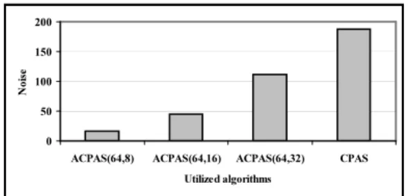
A generated fringe pattern by the Fresnel model has a contin-ues spatial frequency distribution. Therefore, the diffracted light by the fringe is steered to a designed direction. However, the generated fringe pattern by the CS has a discrete spatial frequency distribution. This causes noise on the reconstructed image because the diffracted light by the each segment on the fringe pattern may not be steered to the exact designed direction. In order to understand the effect of noise, the re-constructed images are compared to the rere-constructed image from the Fresnel hologram. In this experiment, a single point located at the center position of a hologram display area is used as the input. Various methods are utilized such as Fres-nel hologram, PAS without FFT, PAS with FFT, CPAS, APAS and ACPAS as the fringe generation algorithm [6, 9, 11, 12]. The measured intensity distributions of the reconstructed im-ages for each case are shown in Fig. 1. In the parenthesis of APAS and ACPAS notation, first and second terms mean IFFT size and segment size, respectively. As seen in Fig. 1, the Fresnel hologram and the PAS without FFT give a single peak without any noise. Here, the highest peak means the reconstructed object, and the other components are the noise which is caused by inaccurate superposition of the diffracted light. The other methods have a single high peak with some noise around it. The total noise levels of each reconstructed image are shown in Fig. 2. Although the reconstructed im-ages of the improvements of the CS have some noise, these methods are acceptable fringe generation algorithms because they are much faster than that of the Fresnel hologram, and the noise may not be noticeable by the observer. These improve-ments, particularly the ACPAS and the CPAS, can be utilized for real-time holographic display systems, and can be selected according to the computational performance of a used sys-tem. The peak-signal-to-noise ratio (PSNR) is used as the objective quality assessment method. The mean squared er-ror (MSE) which for two m × n reconstructed images IrF H
Fig. 1. Intensity distributions of reconstructed images. 0 50 100 150 200
ACPAS(64,8) ACPAS(64,16) ACPAS(64,32) CPAS Utilized algorithms
N
oi
se
Fig. 2. Total power except the single peak. respectively, is determined as,
M SE = 1 mn m−1X i=0 n−1 X j=0 (IrF H(i, j) − IrCS(i, j))2, (3)
and the PSNR is computed as,
P SN R = 10 · log10 µ 2552 M SE ¶ . (4)
The measured results are shown in Fig. 3. The ACPAS (64,08) yields highest noise power among other tested algorithms. One interesting result is that even the reconstruction of the PAS with FFT has a low spread of peaks as shown in Fig. 1, it yields a higher noise level because not only peaks at center area but also whole reconstruction area, which is zero, also contributes to the PSNR. Therefore, a suitable objective qual-ity assessment method for holography is superior and desir-able.
4. ACPAS ACCELERATION ON GPU
A graphics processing unit (GPU) is a processor attached to a graphics card dedicated to calculating floating point oper-ations. Modern GPUs are very efficient to use for scientific computing, because their highly parallel structure makes them more effective than general-purpose CPUs for a range of com-plex algorithms. The CS computes each segment separately, and all segments share the source input object points for this
0 10 20 30 40 50 60 70 80
ACPAS(64,08) ACPAS(64,16) ACPAS(64,32) CPAS(64) PAS(FFT)
Utilized algorithms
PSN
R
[dB
]
Fig. 3. Measured PSNR results corresponding to the recon-structed images of various fringes.
computation. Therefore, this show that the CS algorithm can be easily mapped to a single instruction multiple data archi-tecture, and thus the ACPAS computing can significantly ben-efit from GPU based implementations.
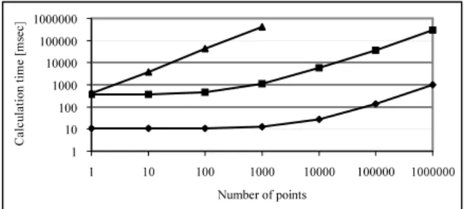
In this work, the latest version ACPAS has been imple-mented based on multi-GPU using Compute Unified Device Architecture (CUDA) as a programming environment. The computation of the ACPAS is performed in three steps: cal-culation of spatial frequencies and phases in each segment, IFFT for each segment, and normalization of the complex fringe pattern. In order to accelerate the ACPAS computa-tion, the three steps are implemented not on CPU but on GPU. The CPU just controls the GPU computing flow and data flow between the computer main memory and GPU memory. Computation times corresponding to the CGH generation al-gorithms for different number of object points are shown in Fig. 4. By the multi GPU computing environment, we could achieve up to 300 times faster computation compared to a typ-ical CPU-based implementation.
One mega-pixel frame size full color holograms can be generated at a rate of 30 frames per second for objects with more than 10,000 points. Comparative results for the ACPAS on a CPU and on three GPUs are shown in Fig. 4. The used parameters in this experiment are as follow: the hologram size is 1K × 1K pixels; the IFFT size is 64 × 64 pixels and the corresponding segment size is 32 × 32 pixels. The comput-ing system has two Intel(R) Xeon(R) CPU 2GHz, 8-GByte memory and three NVIDIA GeForce GTX 280 video cards.
A 3D model, Rose, is used in this experiment as the input model, and this model is shown in Fig. 5(a). The used dense 3D object points are extracted from the 3D model, and are used to generate hologram patterns using the Fresnel holo-gram, the CPAS, and the ACPAS algorithms, for compari-son. The reconstructed images are shown in Fig. 5(b) - 5(d). The used 3D object consisted of about 9,000 vertices, and therefore, the rendered images are photorealistic. The re-constructed image using the CPAS is not clear, and seems to have some noise. On the other hand, the quality of the re-constructed images using the ACPAS and the unapproximated Fresnel holograms are similar.
1 10 100 1000 10000 100000 1000000 1 10 100 1000 10000 100000 1000000 Number of points Ca lc ul at io n tim e [ m se c]
Multi GPU-based ACPAS CPU-based ACPAS CPU-based Fresnel hologram Fig. 4. Calculation-time comparison between CPU-based and GPU-based implementations.
(a) 3D model (b) Fresnel (c) CPAS (d) ACPAS Fig. 5. A perspective image of the used 3D model, Rose, and reconstructed images.
5. CONCLUSION
Various quality improvements for the CS are described. These improvements are due to phase compensation and reduction of frequency discretization step-size. The reconstructed im-ages using these methods are compared to the reconstructed images from the Fresnel holograms, where a single point ob-ject is used as the input. The reconstructed images due to the improvements have a single high peak with lower un-wanted components (noise). The latest version, ACPAS, has the highest peak with lowest noise. The reconstruction us-ing the ACPAS is quite similar to the reconstruction from the Fresnel hologram. And even if it has some noise, this method is acceptable because it is much faster than that the Fresnel hologram case, and the noise can be neglected, since it is not noticeable.
Furthermore, the speed up due to multi-GPU implemented ACPAS is discussed. We can generate high quality hologram patterns in real-time as a consequence of a speed up factor of about 300 compared to CPU-based implementations. The digital holograms generated by the ACPAS can be computed and displayed at a rate of 30 fps for photorealistic scenes rep-resented by ten thousands of object points.
6. REFERENCES
[1] T. Ito, N. Masuda, K. Yoshimura, A. Shiraki, T. Shimob-aba, and T. Sugie, “Special-purpose computer horn-5 for a real-time electroholography,” Opt. Express, vol. 13, pp. 1923–1932, March 2005.
[2] J. A. Watlington, M. Lucente, C. J. Sparrell, V. M. Bove, and I. Tamitani, “A hardware architecture for rapid gen-eration of electro-holographic fringe patterns,” in
Prac-tical Holography IX. SPIE, 1995, vol. 2406, pp. 172–
183.
[3] T. Okada, S. Iwata, O. Nishikawa, K. Matsumoto, H. Yoshikawa, K. Sato, and T. Honda, “The fast com-putation of holograms for the interactive holographic 3d display system,” in International Conference on
Appli-cations of Optical Holography. SPIE, 1995, vol. 2577,
pp. 33–40.
[4] M. Lucente, “Interactive computation of holograms us-ing a look-up table,” Journal of Electronic Imagus-ing, vol. 2, pp. 28–34, 1993.
[5] T. Yatagai, “Stereoscopic approach to 3-d display using computer-generated holograms,” Appl. Opt., vol. 15, pp. 2722–2729, August 1976.
[6] M. Yamaguchi, H. Hoshino, T. Honda, and N. Ohyama, “phase-added stereogram: calculation of hologram us-ing computer graphic technique,” in Practical
holo-graphic VII. SPIE, 1993, vol. 1914, pp. 25–33.
[7] H. Yoshikawa and H. Kameyama, “Integral hologra-phy,” in Practical Holograhy IX. SPIE, 1995, vol. 2406, pp. 226–234.
[8] J. Tamai and H. Yoshikawa, “Faster computation of sub-sampled coherent stereogram (in japanese),” Journal of
ITEJ, vol. 50, pp. 1612–1615, 1996.
[9] H. Kang, T. Fujii, T. Yamaguchi, and H. Yoshikawa, “The compensated phase-added stereogram for real-time holographic display,” Optical Engineering, vol. 46, pp. 095802, September 2007.
[10] H. Kang, T. Yamaguchi, and H. Yoshikawa, “Accurate phase-added stereogram to improve the coherent stere-ogram,” Appl. Opt., vol. 47, pp. D44–D54, July 2008. [11] H. Kang, Quality Improvements of the Coherent
Holo-graphic Stereogram for Natural 3D Display and Its Ap-plications, Ph. D. Thesis, Nihon University, Japan, 2008.
[12] H. Kang, F. Yaras¸, L. Onural, and H. Yoshikawa, “Real-time fringe pattern generation with high quality,” in
Dig-ital Holography and Three-Dimensional Imaging. OSA,