Isolation and one-way effects in diffraction on
dielectric gratings with plasmonic inserts
A.E. Serebryannikov1 and Ekmel Ozbay1,*
1
Nanotechnology Research Center-NANOTAM, Department of Physics, Department of Electrical and Electronics Engineering, Bilkent University, 06800 Ankara, Turkey
*Corresponding author: [email protected]
Abstract: Diffraction of plane waves on dielectric gratings with planar plasmonic inserts is studied with the emphasis put on the anomalous selectivity of diffraction orders. It is shown that some formally propagating orders can be suppressed within a wide frequency range. The effect of suppression is more general than the isolation effect observed earlier in zero-permittivity and (near-)zero-index slabs and sensitive to the frequency dependent peculiarities of the field distribution within the plasmonic layer. It is required that the real part of the permittivity of this layer is positive less than unity. The wideband features of the suppression effect, i.e., one-way transmission and diffraction-free reflection are demonstrated. Narrowband selectivity effects are also studied. The structures suggested can be used for extending the potential of technologies that are based on multibeam operation and field transformation.
©2008 Optical Society of America
OCIS codes: (050.1970) Diffractive optics; (050.1960) Diffraction theory; (120.7000)
Transmission; (160.4670) Optical materials; (160.3900) Metals.
References and links
1. R.W. Ziolkowski, “Propagation in and scattering from a matched metamaterial having a zero index of
refraction,” Phys. Rev. E 70, 046608 (2004).
2. A. Alu, M. G. Silveirinha, A. Salandrino, and N. Engheta, “Epsilon-near-zero metamaterials and
electromagnetic sources: Tailoring the radiation phase pattern,” Phys. Rev. B 75, 155410 (2007).
3. A. E. Serebryannikov, T. Magath, K. Schuenemann, and O.Y. Vasylchenko, “Scattering of s-polarized
plane waves by finite-thickness periodic structures made of ultralow-permittivity metamaterials,” Phys. Rev. B 73, 115111 (2006).
4. M. J. Lockyear, A. P. Hibbins, K. R. White, and J. R. Sambles, “One-way diffraction grating,” Phys. Rev. E
74, 056611 (2006).
5. A. E. Serebryannikov, T. Magath, and K. Schuenemann, “Bragg transmittance of s-polarized waves through
finite-thickness photonic crystals with a periodically corrugated interface,” Phys. Rev. E 74, 066607 (2006).
6. J. B. Pendry, A. J. Holden, W. J. Stewart, and I. Youngs, “Extremely low frequency plasmons in metallic
mesostructures,” Phys. Rev. Lett. 76, 4773-4776 (1996).
7. B. T. Schwartz and R. Piestun, “Total external reflection from metamaterials with ultralow refractive
index,” J. Opt. Soc. Am. B 20, 2448-2453 (2003).
8. S. Enoch, G. Tayeb, P. Sabouroux, N. Guerin, and P. Vincent, “A metamaterial for directive emission,”
Phys. Rev. Lett. 89, 213902 (2002).
9. M. Silverihna and N. Engheta, “Design of matched zero-index metamaterials using non-magnetic
inclusions in epsilon-near-zero media,” Phys. Rev. B 75, 075119 (2007).
10. R.W. Ziolkowski and C.-Y. Cheng, “Lumped element models of double negative metamaterial-based
transmission lines,” Radio Sci. 39, RS2017 (2004).
11. N. Katsarakis, G. Konstantinidis, A. Kostopoulos, R. S. Penciu, T. F. Gundogdu, M. Kafesaki, E. N.
Economou, Th. Koschny, and C. M. Soukoulis, “Magnetic response of split-ring resonators in the far-infrared frequency regime,” Opt. Lett. 30, 1348-1350 (2005).
12. L. Jylhä, I. Kolmakov, S. Maslovski, and S. Tretyakov, “Modeling of isotropic backward-wave materials
composed of resonant spheres,” J. Appl. Phys. 99, 043102 (2006).
13. K. Guven, A. O. Cakmak, M. D. Caliskan, T. F. Gundogdu, M. Kafesaki, C. M. Soukoulis, and E. Ozbay,
“Bilayer metamaterial: analysis of left-handed transmission and retrieval of effective medium parameters,” J. Opt. A 9, S361-S365 (2007).
14. W. J. Padilla, M. T. Aronsson, C. Highstrete, M. Lee, A. J. Taylor, and R. D. Averitt, “Electrically resonant terahertz metamaterials,” Phys. Rev. B 75, 041102 (2007).
15. B. Baumeier, T. A. Leskova, and A. A. Maradudin, “Transmission through thin metal film with periodically
and randomly corrugated surfaces,” J. Opt. A 8, S191-S207 (2006).
16. I. R. Hooper and J. R. Sambles, “Coupled surface plasmon polaritons on thin metal slabs corrugated on
both surfaces,” Phys. Rev. B 70, 045421 (2004).
17. M. M. Dvoynenko, I. I. Samoylenko, and J.-K. Wang, “Suppressed light transmission through corrugated
metal films at normal incidence,” J. Opt. Soc. Am A 23, 2315-2319 (2006).
18. N. Bonod, S. Enoch, L. Li, E. Popov, and M. Neviere, “Resonant optical transmission through thin metallic
films with and without holes,” Opt. Express 11, 482-490 (2003).
19. R. A. Depine, A. Lakhtakia, and D. R. Smith, “Enhanced diffraction by a rectangular grating made of a
negative phase-velocity (or negative index) material,” Phys. Lett. A 337, 155-160 (2005).
20. R. A. Depine, M. E. Inchaussandague, and A. Lakhtakia, “Vector theory of diffraction by gratings made of
a uniaxial dielectric-magnetic material exhibiting negative refraction,” J. Opt. Soc. Am. B 23, 514-528 (2006).
21. Z. Wang, J. D. Chong, J. D. Joannopoulos, and M. Soljacic, “Reflection-free one-way edge modes in
gyromagnetic photonic crystals,” Phys. Rev. Lett. 100, 013905 (2008).
22. F. D. M. Haldane and S. Raghu, “Possible realization of directional optical waveguides in photonic crystals
with broken time-reversal symmetry,” arXiv:cond-mat/0503588 (2008).
23. T. Magath and A. E. Serebryannikov, “Fast iterative, coupled-integral-equation technique for
inhomogeneous profiled and periodic slabs,” J. Opt. Soc. Am. A 22, 2405-2418 (2005).
24. R. Petit, Ed., Electromagnetic theory of gratings (Springer, Berlin Heidelberg New York, 1980).
1. Introduction
Recently, it has been demonstrated that the planar slabs of a matched-index metamaterial having a zero index of refraction can transform the cylindrical waves generated by an embedded line source or external curvilinear wave fronts into planar wave fronts [1]. A similar transformation can be realized by using epsilon-near-zero materials [2]. The wave fronts can be transformed in such a way that two regions of space with a rather complex boundary shape can be isolated and the phase pattern in one region can be tailored, while being independent of the excitation shape in the other region. This effect is connected with the fact that the phase variation within an epsilon-near-zero material is small and completely disappears at zero permittivity.
In case a linearly polarized plane wave is incident on the grating with front-side periodic corrugations, which is made of a zero-permittivity material, the isolation effect manifests itself in that some diffraction orders in transmission, which are formally allowed to propagate, can be suppressed [3]. As a result, the transmitted far field is not affected by the front-side corrugations. One more feature, that is related to this effect, is that the transmission can strongly depend on whether the front or back side of the grating is corrugated (these results have not been shown in [3]). This effect is known as one-way transmission and has been studied in detail at microwave frequencies in [4] for multislit gratings, in which the slits are branched in such a manner that the interfaces have different periods. It is noteworthy that a similar effect has been observed in photonic crystals with one-side grating-like corrugations [5].
Materials with near-zero permittivity, ε ≈0, exist in nature at terahertz frequencies (polar dielectrics) and at the visible and ultraviolet (noble metals). They are necessarily dispersive and their permittivities are often well described in the framework of Drude or Drude-Lorentz models. According to [6], Drude-type dispersion can be scaled down to microwave frequencies in arrays of thin metallic wires. Correspondingly, the operation regimes with 0<Reε<1 can be obtained within a wide frequency range. For example, periodic arrays of silver rods have been suggested in [7] for obtaining a metamaterial for wavelengths from 0.5
μm to 1.5 μm. Other performances of epsilon-near-zero and matched zero-index metamaterials have been considered, for example, in [2,8,9]. In the context of our present interest, we should also mention those metamaterials that have been designed to operate at optical or microwave frequencies in the negative-index regime, but also show the ranges with 0<Reε<1, e.g., see [10]-[14].
It is noteworthy that thin metallic films with corrugated interfaces have been studied by many research groups, by putting the emphasis on the anomalous transmission effects, which appear due to surface plasmon polaritons and hence correspond to Reε<0, or to narrowband transmission effects at Reε>0, e.g., see [15]-[17]. A combined structure, which consists of a thin non-corrugated metallic film and periodically located dielectric pillars, has been studied in [18]. Some interesting diffraction effects have been observed in the relief gratings, which are obtained by introducing periodic corrugations on the interface between an air half-space and a half-space that is made of a negative-phase-velocity (negative-index) material [19,20].
In the present paper, we study diffraction on three-layer gratings, which consist of the inner non-corrugated plasmonic layer and the outer corrugated dielectric layers, while the permittivity of the plasmonic layer is smaller than unity but positive. In some theoretical performances, one of the dielectric layers is removed, in turn leading to two-layer gratings. It will be shown here that the isolation effect can appear within a wide range of Reε varying in line with the Drude model, i.e., the (near-)zero phase variation is not a necessary condition. For the structures considered, this leads to the appearance of several anomalous diffraction effects, which manifest themselves in the wideband suppression of some propagating diffraction orders and, hence, can be characterized in terms of the diffraction order selectivity. In particular, we will demonstrate that the one-way transmission can be achieved within a wide frequency range. It is distinguished from the recently suggested performances, in which this effect is narrowband. On the other hand, it is distinguished from a transmission that is associated with surface plasmon polaritons at negative Reε, which is a rather narrowband effect. In fact, the used plasmonic materials can be the same as those in [15]-[18], but correspond in most cases to another frequency range. In our case, plasmonic layers have flat interfaces, so that the regions, which are mainly responsible for the isolation and diffraction effects, are different. This feature distinguishes the suggested gratings from the two-layer gratings considered in [3] but makes them similar to some of those in [18]. Note that the considered isolation mechanism differs from that occurring due to the reflection-free edge modes in gyromagnetic and gyroelectric crystals [21,22], since no anisotropic material is required in our case. All effects studied in this paper are in accordance with the reciprocity theorem. To numerically solve the diffraction problem, we use a flexible and efficient self-made solver, which is based on the fast coupled-integral-equations technique [23].
2. Theoretical background
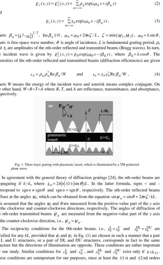
General geometry of the suggested structures is shown in Fig. 1. The planar plasmonic layer is sandwiched between two dielectric layers, at least one of which has a periodically corrugated interface. The upper (front-side) and lower (back-side) interfaces are assumed to be set by
) / 2 cos( / ) ( 1 1 1 x h=A+B πxM L+φ f and f2(x)/h=C+Dcos(2πxM2/L+φ2), (1) respectively, where h is the total thickness. We refer to the structure shown in Fig. 1 as a DU structure (Double corrugations, Upper interface determines the period of the whole structure). In this case, M2/M1 is an integer larger than unity. Correspondingly, M1/M2 is an integer larger
than unity for a DL structure (Double corrugations, Lower Interface). If D=0, then we obtain a U structure. In turn, L structures correspond to B=0. The upper and lower dielectric layers are assumed to be made of dielectrics with ε=εU and ε=εL, respectively. The permittivity of the
plasmonic insert (a<y<b) satisfies the Drude model, i.e., it is given by )] ( /[ 1 ) (ω ω2 ω ω γ
εi = − p +i , where ωp and γ mean plasma and collision frequencies. It is
assumed that A+B≤1, C−D≥0, C+D≤a/h, and A−B≥b/h.
Consideration is restricted to the case of TM polarization. We assume that the plane wave is incident on a grating, as shown in Fig. 1. The electric fields in the upper (y>h) and lower (y<0) half-spaces are presented as follows:
) exp( ) , ( ) , (x y E x y i x i y E n n n n i z z = + ∑ρ α + β ∞ −∞ = (2) and ) exp( ) , (x y i x i y E n n n n z = ∑τ α − β ∞ −∞ = , (3) where β [ 2 α2]1/2 n n= k − , Imβn≥0, αn=α0+2πnζ /L, ζ =min{M1,M2}, α0=ksinθ,
k=ω/c is free-space wave number, θ is angle of incidence, L is fundamental grating period, ρn
and τn are amplitudes of the nth-order reflected and transmitted beams (Bragg waves). In turn,
the incident wave is given by Eiz(x,y)=E0exp(iα0x−iβ0y), where β0=kcosθ. The
intensities of the nth-order reflected and transmitted beams (diffraction efficiencies) are given by
W
rn=ρnρ*nReβn/ and tn=τnτn*Reβn/W , (4)
where W means the energy of the incident wave and asterisk means complex conjugate. On the other hand, W=R+T+A where R, T, and A are reflectance, transmittance, and absorptance, respectively.
Fig. 1. Three-layer grating with plasmonic insert, which is illuminated by a TM polarized plane wave.
In agreement with the general theory of diffraction gratings [24], the nth-order beams are propagating if k>kn where kn=2πn/(1±sinθ)L. In the latter formula, signs + and –
correspond to sgnn≠sgnθ and sgnn=sgnθ, respectively. The nth-order reflected beams diffract at the angles ψn, which can be obtained from the equation sinψn=sinθ+2πnζ/kL.
It is assumed that the angles ψn and θ are measured from the positive-value part of the y axis
in the clockwise and counter-clockwise directions, respectively. The angles of diffraction of the nth-order transmitted beams ψˆn are measured from the negative-value part of the y axis in the counter-clockwise direction, i.e., ψˆn=ψn.
The reciprocity conditions for the 0th-order beams, i.e., tL0=t0U and tDL0 =tDU0 are satisfied for any kL, provided that φ1and φ2 in Eq. (1) are chosen in such a manner that a pair of L and U structures, or a pair of DL and DU structures, corresponds in fact to the same structure but the directions of illumination are opposite. These conditions are rather important for our study. Similar conditions for rL0 and r0U, and r0DL and rDU0 exist only if k<k±1.
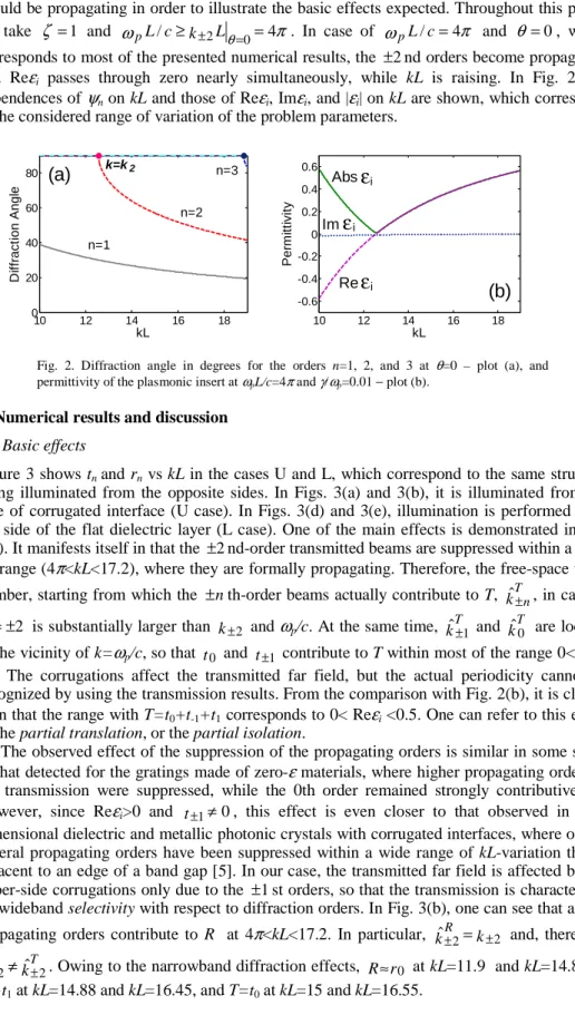
should be propagating in order to illustrate the basic effects expected. Throughout this paper, we take ζ =1 and ω / θ 4π 0 2 = ≥k± L = c L
p . In case of ωpL/c=4π and θ =0, which
corresponds to most of the presented numerical results, the ±2nd orders become propagating and Reεi passes through zero nearly simultaneously, while kL is raising. In Fig. 2, the
dependences of ψn on kL and those of Reεi, Imεi, and |εi| on kL are shown, which correspond
to the considered range of variation of the problem parameters.
10 12 14 16 18 0 20 40 60 80 kL D if fr ac ti on A ngl e n=1 n=2 n=3 k=k2
(a)
10 12 14 16 18 -0.6 -0.4 -0.2 0 0.2 0.4 0.6 kL P e rm itti v ity(b)
Im Re Absε
ε
ε
i i iFig. 2. Diffraction angle in degrees for the orders n=1, 2, and 3 at θ=0 – plot (a), and
permittivity of the plasmonic insert at ωpL/c=4π and γ/ωp=0.01 − plot (b).
3. Numerical results and discussion
3.1 Basic effects
Figure 3 shows tn and rn vs kL in the cases U and L, which correspond to the same structure
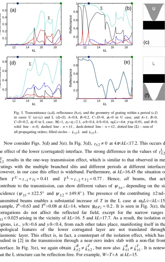
being illuminated from the opposite sides. In Figs. 3(a) and 3(b), it is illuminated from the side of corrugated interface (U case). In Figs. 3(d) and 3(e), illumination is performed from the side of the flat dielectric layer (L case). One of the main effects is demonstrated in Fig. 3(a). It manifests itself in that the ±2nd-order transmitted beams are suppressed within a wide
kL-range (4π<kL<17.2), where they are formally propagating. Therefore, the free-space wave number, starting from which the ±nth-order beams actually contribute to T, kˆT±n, in case of
2 ± =
n is substantially larger than k±2 and ωp/c. At the same time, kˆT±1 and k T
ˆ0 are located in the vicinity of k=ωp/c, so that t0 and t±1 contribute to T within most of the range 0< Reεi
<1. The corrugations affect the transmitted far field, but the actual periodicity cannot be recognized by using the transmission results. From the comparison with Fig. 2(b), it is clearly seen that the range with T=t0+t-1+t1 corresponds to 0< Reεi <0.5. One can refer to this effect
as the partial translation, or the partial isolation.
The observed effect of the suppression of the propagating orders is similar in some sense to that detected for the gratings made of zero-ε materials, where higher propagating orders in the transmission were suppressed, while the 0th order remained strongly contributive [3]. However, since Reεi>0 and t±1≠0, this effect is even closer to that observed in
two-dimensional dielectric and metallic photonic crystals with corrugated interfaces, where one or several propagating orders have been suppressed within a wide range of kL-variation that is adjacent to an edge of a band gap [5]. In our case, the transmitted far field is affected by the upper-side corrugations only due to the ±1st orders, so that the transmission is characterized by wideband selectivity with respect to diffraction orders. In Fig. 3(b), one can see that all the propagating orders contribute to R at 4π<kL<17.2. In particular, kˆR±2=k±2 and, therefore,
k
kˆR±2≠ ˆT±2. Owing to the narrowband diffraction effects, R≈r0 at kL=11.9 and kL=14.8, T=
12 14 16 18 0 0.1 0.2 0.3 0.4 0.5 kL T ra n sm itta n c e (a) Σ 12 14 16 18 0 0.2 0.4 0.6 0.8 1 kL Re fl e c ta n c e (b) Σ 12 14 16 18 0 0.2 0.4 0.6 0.8 kL T ra n s m it ta n c e (d) Σ 12 14 16 18 0 0.2 0.4 0.6 0.8 1 kL Re fl e c ta n c e (e)
Fig. 3. Transmittance (a,d), reflectance (b,e), and the geometry of grating within a period (c,f)
in cases U (a)-(c) and L (d)-(f); A=0.8, B=0.2, C=D=0, φ1=0 in U case, and A=1, B=0,
C=D=0.2, φ2=0 in L case; Μ1=1, εU=εL=2.1, a/h=0.4, b/h=0.6, ωpL/c=4π, γ/ωp=0.01, and θ=0;
solid line – n=0, dashed line - n=±1, dash-dotted line - n=±2, dotted line (Σ) – sum of
all propagating orders; filled circles – k±2L and k±3L.
Now consider Figs. 3(d) and 3(e). In Fig. 3(d), t±2≠0 at 4π<kL<17.2. This occurs due to the effect of the lower (corrugated) interface. The strong difference in the values of tL±2 and tU±2 results in the one-way transmission effect, which is similar to that observed in metallic gratings with the multiple branched slits and different periods at different interfaces [4]. However, in our case this effect is wideband. Furthermore, at kL=16.45 the situation occurs when U≈ 1+ 1≈0.41
− t
t
T and TL≈t−2+t2≈0.77. Hence, all beams, that actually
contribute to the transmission, can show different values of ψ±n, depending on the side of incidence (ψ±1=±22.5° and ψ±2=±49.8°). The presence of the contributing ±2nd-order transmitted beams enables a substantial increase of T in the L case at ωpL/c<kL<15. For
example, TL=0.63 and TU=0.08 at kL=14, where Reεi≈0.2. It is seen in Fig. 3(e), that the corrugations do not affect the reflected far field, except for the narrow ranges with
025 . 0
1<
±
t arising in the vicinity of kL=16. 5 and kL=17.7. As a result, the isolation of two regions, i.e., y/h>0.6 and y/h<0.4, from each other takes place, manifesting itself in that the topological features of the lower corrugated layer are not translated through the plasmonic layer. This effect is, in fact, a counterpart of the isolation effect, which has been studied in [2] in the transmission through a near-zero index slab with a non-flat front-side interface. In Fig. 3(e), we again obtain kˆR±2≠kˆT±2, but now also kˆ±R1≠kˆT±1. It is noteworthy that the L structure can be reflection-free. For example, W=T+A at kL=15.
12 14 16 18 0 0.1 0.2 0.3 0.4 0.5 kL T ra n sm itta n c e (a) Σ 12 14 16 18 0 0.2 0.4 0.6 0.8 1 kL Re fl e c ta n c e (b) Σ 12 14 16 18 0 0.1 0.2 0.3 0.4 0.5 0.6 kL T ra n s m it ta n c e (d) Σ 12 14 16 18 0 0.2 0.4 0.6 0.8 1 kL Re fl e c ta n c e (e)
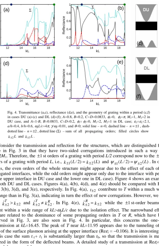
Fig. 4. Transmittance (a,c), reflectance (d,e), and the geometry of grating within a period (c,f)
in cases DU (a)-(c) and DL (d)-(f); A=0.8, B=0.2, C=D=0.0833, φ1=0, φ2=π, M1=1, M2=2 in
DU case, and A=1-B, B=0.0833, C=D=0.2, φ1= φ2=0, M1=2, M2=1 in DL case; εU=εL=2.1,
a/h=0.4, b/h=0.6, ωpL/c=4π, γ/ωp=0.01, and θ=0; solid line – n=0, dashed line - n=±1,
dash-dotted line - n=±2, dotted line (Σ) – sum of all propagating orders; filled circles show
L
k±2 and k±3L.
Consider the transmission and reflection for the structures, which are distinguished from those in Fig. 3 in that they have two-sided corrugations introduced in such a way that
M2=2M1. Therefore, the ±1st orders of a grating with period L/2 correspond now to the ±2nd
orders of a grating with period L, i.e., k±1(L/2)=k±2(L) and ψ±1(L/2)=ψ±2(L). In other words, the even orders of the whole structure might appear due to the effect of each of the corrugated interfaces, while the odd orders might appear only due to the interface with period
L (the upper interface in DU case and the lower one in DL case). Figure 4 shows an example
for both DU and DL cases. Figures 4(a), 4(b), 4(d), and 4(e) should be compared with Figs. 3(a), 3(b), 3(d), and 3(e), respectively. In Fig. 4(a), t±2 contribute to T within a much wider
kL-range than in Fig. 3(a), indicating in turn the effect of new corrugations. However, we still
have kˆT±2>k±2 and k kR T
2 2
ˆ± ≠ ± . In Fig. 4(e), kˆ±R2=k±2 while the ±1st-order beams are
absent within a wide range of kL>ωpL/c due to the isolation effect. The narrowband effects
that are related to the dominance of some propagating orders in T or R, which have been observed in Fig. 3, are also seen in Fig. 4. In particular, this concerns the one-way transmission at kL=16.45. The peak of T near kL=11.95 appears due to the tunneling of the field of the surface plasmon arising at the upper interface (Reεi = −0.106). It is interesting that
in this case the sum t-1+ t1 is substantially larger than t0, so that the transmission is mainly
realized in the form of the deflected beams. A detailed study of a transmission at Reεi<0 is
beyond the scope of the present paper.
To better understand the mechanism leading to the order selectivity, we consider near-field patterns (in units of |Ez|) within a single grating period, i.e., at 0<x<L and 0<y<h. Several
examples are shown in Fig. 5, which correspond to the typical behaviors of tn and rn in Figs. 3
and 4. First, we compare Figs. 5(a) and 5(b) corresponding to the two cases (L and DL), which only differ in the shape of the upper-side interface. Three typical regions can be recognized in each figure. Within the lower region (0<y/h<0.4), the field patterns are nearly
the same. Four maxima of |Ez(x,y)| occur at y=0 within the period, which can be associated
with the ±2nd orders. Indeed, T≈t−2+t2 at kL=16.45 in Figs. 3(d) and 4(d). In the upper
region (0.6<y/h<1), |Ez(x,y)| in Figs. 5(a) and 5(b) is completely different, that indicates the
effect exerted by the upper interface. Four maxima occur at y=const at least within a part of the upper region in Fig. 5(b). In this case, R≈r0+r−2+r2, see Fig. 4(e). Since the field topology at y<0.4 is not affected by the shape of the upper layer, the middle region (0.4<y/h<0.6) isolates the two others.
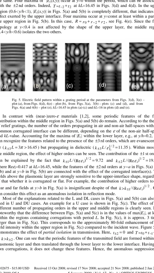
Fig. 5. Electric field pattern within a grating period at the parameters from Figs. 3(d), 3(e) – plot (a), from Figs. 4(d), 4(e) – plot (b), from Figs. 3(a), 3(b) – plots (c) and (d), and from
Figs. 4(a) and 4(b) – plot (e); kL=16.45 in plots (a)-(c) and kL=16 in plots (d) and (e).
In contrast with (near-)zero-ε materials [1,2], some periodic features of the field distribution within the middle region in Figs. 5(a) and 5(b) do remain. According to the theory of relief gratings, the number of the orders propagating in air and non-air half-spaces with the common corrugated interface can be different, depending on the ε of the non-air half-space and kL-value. Accounting for the maxima of |Ez| within the lower layer, e.g., at y/h=0.2, one
can recognize the features related to the presence of the ±3rd orders, which are evanescent in air (k±3L=3π >16.45) but propagating in dielectric (k±3L/ε1L/2=11.35). Within most of the middle region, the effect of higher orders can be seen. The contribution of the ±1st orders can be explained by the fact that k±1L/(Reεi)1/2=9.72 and k±2L/(Reεi)1/2=19.45, where Reεi=0.417 at kL=16.45, while the features of the ±2nd orders at y=a in Figs. 5(a) and
5(b) and at y=b in Fig. 5(b) are connected with the effect of the corrugated interface(s). The fields above the plasmonic layer are strongly sensitive to the upper-interface shape, regardless of that whether it is corrugated or flat. For example, the contribution of higher orders to the near and far fields at y>b in Fig. 5(a) is insignificant despite of that k>k±1/(Reεi)1/2. One can consider this effect as an anomalous isolation in reflection mode.
Most of the explanations related to the L and DL cases in Figs. 5(a) and 5(b) can also be used in U and DU cases. An example for a U case is shown in Fig. 5(c). The effect of the different number of propagating orders in the upper and middle regions is clearly seen. It is noteworthy that the difference between Figs. 5(a) and 5(c) is in the values of max|Ez|, at least
within the regions containing corrugations with period L. In Fig. 5(c), it is approx. 3 times larger than in Fig. 5(a). This corresponds to the approximately 80-fold enhancement of the field intensity within the upper region in Fig. 5(c) compared to the incident wave. Figure 5(c) demonstrates the effect of partial isolation in transmission. Here, t±2=0 and T≈t0+t−1+t1
at k>k±2. One can see that the periodic features of the transmitted field are formed within the
plasmonic layer and then translated through the lower layer to the lower interface. Having no own corrugations, it does not change these features. Hence, the anomalous suppression of
the±2rd orders within a wide kL-range [Fig. 3(a)] can simply be explained in terms of the
periodicity reduction by the plasmonic layer.
Figures 5(d) and 5(e) show a field pattern in the U and DU cases, when t0≠0 but the 1
± st orders dominate in T and the 0th order dominates in R. It is seen that the field topologies differ only within the lower region due to the shape of the lower interface. Again, the plasmonic layer reduces the periodicity, while the role of the upper and lower regions depends on the presence of corrugations. From the presented results, it follows that the structures suggested can provide one with a powerful tool for controlling the number of beams actually contributing to the transmission and reflection and the topology of the near field.
One can use the following condition for U-case transmission. If 1
Reεi< and k±p/(Reεi)1/2<k<k±(p+1)/(Reεi)1/2 , (5)
the field features, which correspond to the orders with |n|=0,1,…p, can be translated to the lower half-space (partial translation), while those corresponding to |n|= p+1, p+2,… cannot be translated (partial isolation). If the condition k<k±1/(Reεi)1/2 is satisfied, i.e., p=0 and
k0=0 in Eq. (5), no periodic feature can appear within the plasmoniclayer. Therefore, the
effect of the upper corrugated interface on the transmitted far field would be reduced, so that the condition Reεi=0 is not necessary for achieving the total isolation (TU≈t0). This case
corresponds to the wave front flattening [1,2], which can be considered as a special case of the periodicity reduction. To obtain Eq. (5), it has been assumed that Imεi=0.
It can be shown that such a kL range always exists near any ω=ωp that all the higher
orders are evanescent within the plasmonic layer, provided that 0<Reεi<1 and Imεi=0. Indeed, ∞
=
±n/(Reεi)1/2
k at Reεi=0 and is decreased with raising Reεi, tending to k±n at Reεi=1.
All the higher orders (|n|>0) are evanescent if
) / ( /c k k21 p c 2 p ω ω < < ± + . (6)
The total isolation is always a wideband effect, because the all materials with Reεi<1 are
necessarily dispersive. The band width is determined by the values of dReεi /dω and can be
relatively large for the typical parameters of the Drude model. In particular, this explains why k
c
k±1<ωp/ < ˆT±1. Correspondingly, the range of achievable values of the ±1st-order
diffraction angles is limited by
⎥⎦ ⎤ ⎢⎣ ⎡ + < − ± ±1 sin 1 2π/ (k 1L)2 (ωpL/c)2 ψ .
For example, ψ±1<26.5°at ωpL/c=4π and ( ) ( / ) 14.05 2
1 2+ =
= k± L L c
kL ωp . A rather
strong contribution of the higher orders to T at kL<14.05 in Figs. 3 and 4 can be explained by the fact that the thickness of the plasmonic region is not large enough.
3.2 Parametric Study
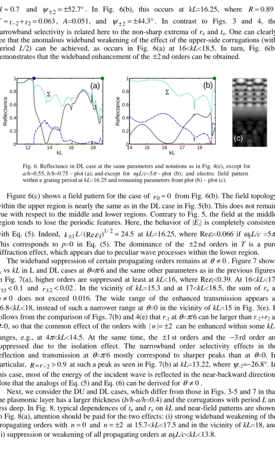
Now, we consider some manifestations of the near- and far-field effects, which are similar to those in Figs. 3-5 and appear at varying the grating parameters. At least in the DL case, the situation can be realized when r0≈0 and R≈r−2+r2, i.e., the reflected far field only
7 . 0 ≈
R and ψ±2=±52.7°. In Fig. 6(b), this occurs at kL=16.25, where R≈0.89, 063 . 0 2 2+ = ≈t− t
T , A=0.051, and ψ±2=±44.3°. In contrast to Figs. 3 and 4, the narrowband selectivity is related here to the non-sharp extrema of rn and tn. One can clearly
see that the anomalous wideband weakening of the effect of the upper-side corrugations (with period L/2) can be achieved, as occurs in Fig. 6(a) at 16<kL<18.5. In turn, Fig. 6(b) demonstrates that the wideband enhancement of the ±2nd orders can be obtained.
12 14 16 18 0 0.2 0.4 0.6 0.8 1 kL Re fl e cta n c e (a) Σ 14 15 16 17 18 0 0.2 0.4 0.6 0.8 1 kL Re fl e cta n c e (b) Σ
Fig. 6. Reflectance in DL case at the same parameters and notations as in Fig. 4(e), except for a/h=0.55, b/h=0.75 – plot (a), and except for ωpL/c=5π – plot (b); and electric field pattern
within a grating period at kL=16.25 and remaining parameters from plot (b) – plot (c).
Figure 6(c) shows a field pattern for the case of r0≈0 from Fig. 6(b). The field topology within the upper region is nearly the same as in the DL case in Fig. 5(b). This does not remain true with respect to the middle and lower regions. Contrary to Fig. 5, the field at the middle region tends to lose the periodic features. Here, the behavior of |Ez| is completely consistent
with Eq. (5). Indeed, k±1L/(Reεi)1/2=24.5 at kL=16.25, where Reεi=0.066 if ωpL/c =5π.
This corresponds to p=0 in Eq. (5). The dominance of the ±2nd orders in T is a pure diffraction effect, which appears due to peculiar wave processes within the lower region.
The wideband suppression of certain propagating orders remains at θ≠0. Figure 7 shows
rn vs kL in L and DL cases at θ=π/6 and the same other parameters as in the previous figures.
In Fig. 7(a), higher orders are suppressed at least at kL<16, where Reεi<0.39. At 16<kL<17, 1
. 0
1<
±
r and r±2<0.02. In the vicinity of kL=15.3 and at 17<kL<18.5, the sum of rn at 0
≠
n does not exceed 0.016. The wide range of the enhanced transmission appears at 16.8<kL<18, instead of such a narrower range at θ=0 in the vicinity of kL=15 in Fig. 3(e). It follows from the comparison of Figs. 7(b) and 4(e) that r-2 at θ=π/6 can be larger than r-2+r2 at θ=0, so that the common effect of the orders with |n|=±2 can be enhanced within some kL-ranges, e.g., at 4π<kL<14.5. At the same time, the ±1st orders and the −3rd order are suppressed due to the isolation effect. The narrowband order selectivity effects in the reflection and transmission at θ=π/6 mostly correspond to sharper peaks than at θ=0. In particular, R≈r−2>0.9 at such a peak as seen in Fig. 7(b) at kL=13.22, where ψ−2=−26.8°. In this case, most of the energy of the incident wave is reflected in the near-backward direction. Note that the analogs of Eq. (5) and Eq. (6) can be derived for θ ≠0.
Next, we consider the DU and DL cases, which differ from those in Figs. 3-5 and 7 in that the plasmonic layer has a larger thickness (b/h-a/h=0.4) and the corrugations with period L are less deep. In Fig. 8, typical dependences of tn and rn on kL and near-field patterns are shown.
In Fig. 8(a), attention should be paid for the two effects: (i) strong wideband weakening of the propagating orders with n=0 and n=±2 at 15.7<kL<17.5 and in the vicinity of kL=18, and (ii) suppression or weakening of all propagating orders at ωpL/c<kL<13.8.
12 14 16 18 0 0.2 0.4 0.6 0.8 1 kL R e fl ec tanc e (a) 10 12 14 16 18 0 0.2 0.4 0.6 0.8 1 kL R e fl ec tanc e (b)
Fig. 7. Reflectance at the parameters from Fig. 3(e) except for θ=π/6 – plot (a), and at the
parameters from Fig. 4(e) except θ=π/6 – plot (b); solid line – n=0, dashed line – n=−1,
dash-dotted line – n=−2, thin solid line – n=−4, dotted line – sum of all propagating
orders; filled circles – k-3L and k-4L.
12 14 16 18 0 0.2 0.4 0.6 0.8 kL T ransm ittanc e (a) Σ 12 14 16 18 0 0.2 0.4 0.6 0.8 1 kL R e flec tan c e (b) Σ
Fig. 8. Transmittance at the same parameters and notations as shown in Fig. 4(a), except for a/h=0.3, b/h=0.7, A=0.85, and B=0.15 – plot (a); reflectance at the same parameters and notations as in Fig. 4(d), except for a/h=0.3, b/h=0.7, and C=D=0.15 – plot (b); electric field pattern within a grating period at kL=15.8 and the remaining parameters from plot (a) – plot (c), and at kL=16 and the remaining parameters from plot (b) – plot (d).
The former case is associated with a wideband one-way transmission effect (compare to [4]). In the vicinity of kL=18, we obtain a similar situation as in Figs. 3(a) and 3(c) at
kL=16.45, i.e., TDU≈t−1+t1 and TDL≈t−2+t2, but here it occurs for a structure with
two-side corrugations. This case corresponds to 0<Reεi<0.17. According to Eq. (6), the total
isolation should occur at kL<14.05. On the other hand, the weakening of the 0th-order transmission at 4π<kL<14.05 is related to the increase of the thickness of the middle region, which now shows near-zero Reεi.
From the comparison of Figs. 8(b) and 4(e), one can see that the wideband suppression of the ±1st-order beams and the typical behavior of the ±2nd-order beams do remain. The only exception is probably related to the relatively wide range in the vicinity of kL=17.8, where
r
R≈ 0. Some features of the near field are shown in Figs. 8(c) and 8(d). Figure 8(c)
corresponds to the case with the 0th and ±1st orders being dominant in R and the ±1st orders being dominant in T, while Reεi≈0.37. One can see how the periodic features that are associated with the ±1st orders are enhanced within the plasmonic layer and then translated to the lower half-space. In comparison with Fig. 5(d), this regime is realized here, while the lower interface is corrugated with period L/2. Although the effect of the ±2nd orders is seen within the lower region, the peculiar near-field distribution leads to the fact that their contribution to the transmitted far field is vanishing. Therefore, not only the actual upper-side periodicity but also the actual lower-side periodicity can be unseen for an observer located in the far zone at y<0. Figure 8(d) provides one with an example of another typical near field
distribution, where the contribution of the 0th order within the plasmonic layer is strong, leading to some flatness. Despite of this, the effect of the 0th order on T is relatively weak.
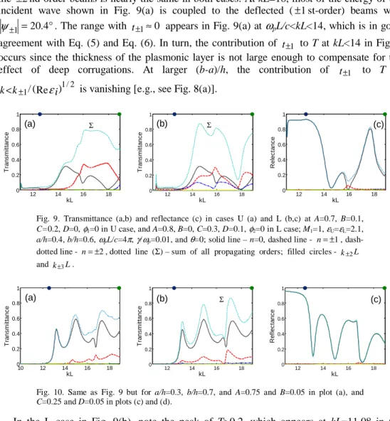
Figure 9 shows tn and rn vs kL for the structures with a smaller h/L than in Figs. 3-8. This
is obtained due to the use of more thin dielectric layers, while (b-a)/L is kept. It is seen that the basic effects related to the isolation regime, i.e., suppression of some higher propagating orders in transmission and all such orders in reflection do remain. A comparison of Fig. 3(a) with Fig. 9(a) shows that T is larger in the latter case, at least at 15<kL<18. The suppression of the ±2nd-order beams is nearly the same in both cases. At kL=18, most of the energy of the incident wave shown in Fig. 9(a) is coupled to the deflected (±1st-order) beams with
° =
±1 20.4
ψ . The range with t±1≈0 appears in Fig. 9(a) at ωpL/c<kL<14, which is in good
agreement with Eq. (5) and Eq. (6). In turn, the contribution of t±1 to T at kL<14 in Fig. 3
occurs since the thickness of the plasmonic layer is not large enough to compensate for the effect of deep corrugations. At larger (b-a)/h, the contribution of t±1 to T at
) Re ( / 1/2 1 εi k
k< ± is vanishing [e.g., see Fig. 8(a)].
12 14 16 18 0 0.2 0.4 0.6 0.8 1 kL T rans m it tanc e (a) Σ 12 14 16 18 0 0.2 0.4 0.6 0.8 1 kL T rans m it tanc e (b) Σ 12 14 16 18 0 0.2 0.4 0.6 0.8 1 kL R e lec tanc e (c)
Fig. 9. Transmittance (a,b) and reflectance (c) in cases U (a) and L (b,c) at A=0.7, B=0.1, C=0.2, D=0, φ1=0 in U case, and A=0.8, B=0, C=0.3, D=0.1, φ2=0 in L case; M1=1, εU=εL=2.1, a/h=0.4, b/h=0.6, ωpL/c=4π, γ/ωp=0.01, and θ=0; solid line – n=0, dashed line - n=±1,
dash-dotted line - n=±2, dotted line (Σ) – sum of all propagating orders; filled circles - k±2L
and k±3L. 10 12 14 16 18 0 0.2 0.4 0.6 0.8 1 kL T rans m it tanc e (a) 12 14 16 18 0 0.2 0.4 0.6 0.8 1 kL T rans m it tanc e (b) Σ 12 14 16 18 0 0.2 0.4 0.6 0.8 1 kL R e fl ec tanc e (c)
Fig. 10. Same as Fig. 9 but for a/h=0.3, b/h=0.7, and A=0.75 and B=0.05 in plot (a), and C=0.25 and D=0.05 in plots (c) and (d).
In the L case in Fig. 9(b), note the peak of T>0.2, which appears at kL=11.08 in the surface-plasmon regime (Reεi≈−0.29). For larger thicknesses of the dielectric layers, this effect has been observed in DU and DL cases only (compare with Figs. 3 and 4). In the comparison with Figs. 3(a) and 3 (d), both narrowband and wideband one-way transmission effects become weaker. No principal difference appears in the reflected far field, see Fig. 9(c). In Fig. 10, the kL-dependences of tn and rn are presented for the structures, which differ
from those in Fig. 9 in that they have a thicker plasmonic layer and less deep corrugations with period L. As was expected, the suppression of the ±1st orders at kL<14 in the U case in Fig. 10(a) is more pronounced than Fig. 9(a). A comparison with [5] gives one an idea of how to explain a similar effect in metallic photonic crystals with the grating-like corrugations. The used modifications of the layer thicknesses result in a stronger wideband contribution of t0
than in Fig. 9. The ±2nd orders are suppressed even at those kL values, at which they contribute to T in the U case in Figs. 9(a) and 3(a). Furthermore, the wideband weakening of the contribution of t±2 to T occurs even in L case [compare Figs. 9(b) and 10(b)]. These
examples show that the effect of the corrugations in producing the higher transmitted orders is weakening with a decreasing corrugation depth in both the U and L cases. The contribution of the higher orders to R also becomes weaker [compare Figs. 9(c) and 10(c)].
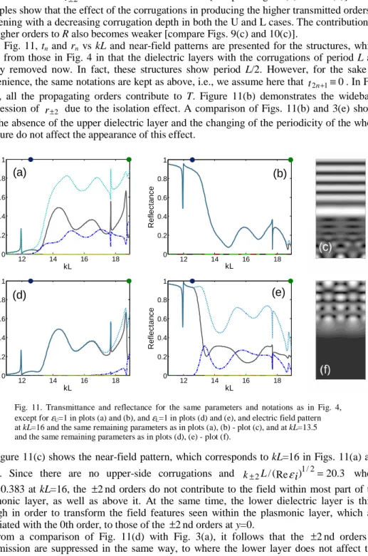
In Fig. 11, tn and rn vs kL and near-field patterns are presented for the structures, which
differ from those in Fig. 4 in that the dielectric layers with the corrugations of period L are simply removed now. In fact, these structures show period L/2. However, for the sake of convenience, the same notations are kept as above, i.e., we assume here that t2n+1≡0. In Fig. 11(a), all the propagating orders contribute to T. Figure 11(b) demonstrates the wideband suppression of r±2 due to the isolation effect. A comparison of Figs. 11(b) and 3(e) shows
that the absence of the upper dielectric layer and the changing of the periodicity of the whole structure do not affect the appearance of this effect.
12 14 16 18 0 0.2 0.4 0.6 0.8 1 kL T ra n s m it ta n c e (a) 12 14 16 18 0 0.2 0.4 0.6 0.8 1 kL R e fl ec ta nc e (b) 12 14 16 18 0 0.2 0.4 0.6 0.8 1 kL T ra n sm itta n c e (d) 12 14 16 18 0 0.2 0.4 0.6 0.8 1 kL Re fl e c ta n c e (e)
Fig. 11. Transmittance and reflectance for the same parameters and notations as in Fig. 4,
except for εU=1 in plots (a) and (b), and εL=1 in plots (d) and (e), and electric field pattern
at kL=16 and the same remaining parameters as in plots (a), (b) - plot (c), and at kL=13.5 and the same remaining parameters as in plots (d), (e) - plot (f).
Figure 11(c) shows the near-field pattern, which corresponds to kL=16 in Figs. 11(a) and 11(b). Since there are no upper-side corrugations and k±2L/(Reεi)1/2=20.3 where Reεi=0.383 at kL=16, the ±2nd orders do not contribute to the field within most part of the
plasmonic layer, as well as above it. At the same time, the lower dielectric layer is thick enough in order to transform the field features seen within the plasmonic layer, which are associated with the 0th order, to those of the ±2nd orders at y=0.
From a comparison of Fig. 11(d) with Fig. 3(a), it follows that the ±2nd orders in transmission are suppressed in the same way, to where the lower layer does not affect this effect, despite of the fact that the periods of the upper-side corrugations in these two figures are different. This is a quite predictable feature in the context of the consideration related to Fig. 5. Now compare Fig. 11(e) with Fig. 4(e). One can see that the removal of the lower dielectric region exerts an insignificant effect on the reflection. On the other hand, the
comparison of Figs. 11(d) and 4(d) shows that the presence of the lower dielectric layer with the corrugated interface strongly affects the transmission. It is noteworthy that the situation shown in Figs. 11(d) and 11(e) is the same as in the zero-permittivity gratings from [3] in the sense that only the 0th order contributes to T, while all the propagating orders contribute to R. A typical near-field pattern is shown in Fig. 11(f) for the structure from Figs. 11(d) and 11(e). Within the upper region, the field topology is similar to those in Figs. 5(b), 6(c), and 8(d), in turn showing a contribution of r±2 to R. In contrast, no periodic feature appears in Fig. 11(f)
below the plasmonic layer, for which k±1L/(Reεi)1/2=37. In fact, this example is connected with the possibility of obtaining flat transmitted wave fronts at Reεi>0.
12 14 16 18 10-6 10-5 10-4 10-3 10-2 kL T rans m it tanc e (a) t2
Ω
12 14 16 18 10-10 10-8 10-6 10-4 10-2 100 kL T rans m it tanc e (b) 2 tΩ
Fig. 12. Second-order transmittance t 2 for parameters from Figs. 3(a)-3(c), except for γ=0 –
plot (a), and from Figs. 11(d)-11(f), except for γ=0 - plot (b); solid line – P=300 and Q=600,
dashed line – P=200 and Q=400, and dash-dotted line – P=50 and Q=100; energy balance Ω is
shown for all three sets of P and Q by dotted lines, the most upper line corresponds to P=50 and the lowest line does to P=300.
Finally, we demonstrate how strong suppression of formally propagating orders can typically be in the structures considered, and compare it with the achievable numerical accuracy, see Fig. 12. It is seen that t2<10-3 at least at kL<16. The strength of suppression can
be varied due to a proper choice of the grating parameters. The solid and dashed lines in Fig. 12 almost coincide, so that the used number of discretization points over x and y, P and Q [23], is large enough. In addition, the energy balance Ω is presented in Fig. 12, showing that
t2>Ω can be obtained by increasing P and Q. It is important that a rather good convergence of
t2 is achieved even if Ω can further be decreased by appropriately increasing P and Q. It is
noteworthy that at least P=300 and Q=600 were used in all examples presented in Figs. 2-11. 4. Conclusions
To summarize, we have studied diffraction on three- and two-layer gratings with one- and two-side periodic corrugations, in which one layer (insert) is made of a plasmonic material. It was shown that the isolation effect, which has previously been associated with isotropic (near-) zero-ε materials or multislit gratings, can appear within a wide range of variation of the permittivity of the plasmonic layer, allowing for the existence of anomalous wideband effects in the transmission and reflection. In the studied structures, the isolation effect can manifest itself in that some propagating diffraction orders in the transmission and/or reflection are suppressed, giving a new alternative to an anisotropic route of achieving one-way transmission. Most of the observed features can be explained in terms of the periodicity reduction, which is related to the change of the number of the propagating orders from one layer to another. The effect of wave front flattening can be considered as a limiting case of the field periodicity transformation. The actual periodicity of some gratings cannot be detected by a far-zone observer within a wide frequency range.
For example, for the three-layer structure with the upper corrugated interface (U case), the highest transmitted order is determined by the highest order supported by the plasmonic layer. If the wave is incident on the same structure from the opposite side (L case), it is determined by the lower-side corrugations. Either partial or total isolation can be obtained in the transmission, depending on number of the orders, which are allowed to propagate within the plasmonic layer. As a result, wideband one-way transmission can be realized. In other words, transmission can be substantially different when the structure is illuminated from the different sides. A similar narrowband effect can be obtained, in which diffraction orders contributing to the transmission and reflection are different. An anomalous manifestation of the isolation effect in the L case concerns the fact that the reflected field is not affected by the lower-side corrugations and, therefore, takes on no periodic feature, even if some higher orders within the plasmonic layer might be propagating.
These and other effects, which we refer to as the diffraction order selectivity, are affected by two-side corrugations, the thicknesses of plasmonic and dielectric layers, and the presence of a non-corrugated dielectric layer. The isolation effect can result in the fact that the actual cutoff wave numbers are shifted towards larger values compared to those corresponding to Rayleigh frequencies. Furthermore, the actual cut offs for the same orders in reflection and transmission can be different, that is distinguished from conventional diffraction gratings. This effect is similar to that observed earlier in photonic crystals with one-side grating-like corrugations. However, one-way transmission can be achieved in the considered structures within wider frequency ranges. As a next step, the possibility of obtaining selectivity at enhanced (nearly total) transmission will be studied. The demonstrated effects promise to be a basis for a new approach to efficient beam management in multibeam regime and field transformations.
Acknowledgments
This work is supported by the European Union under the projects EU-METAMORPHOSE, EU-PHOREMOST, EU-PHOME, and EU-ECONAM, and by TUBITAK under the Projects Numbers 105E066, 105A005, 106E198, and 106A017. One of the authors (A.S.) thanks TUBITAK for partial support of this work in the framework of the Visiting Scientists Fellowship Program. One of the authors (E.O.) acknowledges partial support from the Turkish Academy of Sciences.