ADVANCED ELECTROMAGNETICS, VOL. 8, NO. 2, MARCH 2019
A Low Profile Wideband Log Periodic Microstrip Antenna Design
for C-Band Applications
Mehmet Yerlikaya
1,*, Seyfettin Sinan Gültekin
2and Dilek Uzer
21Department of Electrical and Electronics Engineering, Karamanoglu Mehmetbey University, Karaman, Turkey 2Department of Electrical and Electronics Engineering, Konya Teknik Univesity, Konya, Turkey
*corresponding author, E-mail: myerlikaya@kmu.edu.tr
Abstract
In this study, a wideband and low profile microstrip log periodic monopole antenna (LPMA) design for C-band applications is presented. The proposed antenna consists of a monopole log periodic patch in the equilateral triangular dimensions with the microstrip line fed and a rectangular ground plane. The antenna has 9×19.8 mm2 overall size,
thickness of 1.6 mm, 4.3 dielectric constant, and 0.02 tangent loss. According to the simulation results, the proposed antenna has a 60% bandwidth while operating in the frequency band of 4.25-7.95 GHz and 5 GHz resonance frequency. The proposed antenna was also prototyped on FR4 substrate and the results obtained from the measurements were quite similar to the simulations.
1. Introduction
Recently, wireless communication systems with the spread of mobile devices have become one of the most important elements of our daily life. The C band defined by the IEEE within the 4-8 GHz range includes many of the most widely used wireless communication standards such as WLAN, WiMAX, satellite communication, ISM band applications and radar applications [1]. Certainly, the most important elements in a wireless system are antennas. In modern wireless communication systems due to the increasing mobility and miniaturization of mobile devices low profile are needed for high mobility and also wideband antennas are needed for high speed data transmission with maximum coverage. According to the Federal Communications Commission (FCC), an antenna must be greater than 1% or at least 500 MHz impedance bandwidth in order to define as a wideband [2].
Microstrip antennas are the most commonly used antennas in wireless communication systems owing to their features such as low profile, light weight, low-cost, easy to integrate planar or non-planar surfaces, easy to be manufactured by a printed circuit board (PCB) technology and compatible with microwave integrated circuits (MIC) [3-4]. Narrow bandwidth is one of the most important disadvantages of conventional microstrip antennas. To overcome this narrowband trouble, a number of different methods can be used, like adding slots [5], using the defected ground structures (DGS) [6] and using the log periodic arrays [7-10].
Conventional log-periodic antennas are known as frequency independent antennas and have relatively high gain and broadband characteristics. Since the antenna’s structures and performances are in the form of the logarithmic function of the frequency, they are called logarithmic periodic or log periodic antennas [4]. The geometry of the log periodic dipole antenna (LPDA) was applied to microstrip structures by several researchers to obtain better antenna performance in terms of wide bandwidth, reduced size and better gain [7-10].
In this study, a microstrip log periodic monopole antenna (LPMA) with a very small size and simple geometry is presented. The antenna model was inspired by a triangular monopole equilateral patch. The proposed LPMA is suitable for almost all C-band applications, especially WLAN 802.11a operating at 5 GHz and 5.8 GHz ISM band applications. The proposed antenna stands out its small size and simple patch geometry compared to other broadband log periodic antennas presented in the literature [7-10]. The proposed LPMA has almost whole C-band coverage with 4.25-7.95 GHz impedance bandwidth. All antenna designs and simulations were performed with method of moments (MoM) based IE3DTM package program [11]. Furthermore,
the VSWR simulations of the proposed antenna is also verified by Ansys HFSSTM [12]. In addition, the proposed
antenna is also prototyped on FR4 substrate with 1.6 mm thickness and VSWR measurements of the LPMA were performed. It is seen that simulation and measured results are quite similar.
2. Antenna Design
Two dimensional (2D) form of the proposed LPMA are given in Figure 1 for both top and bottom view. As shown in Figure 1, the proposed antenna structure has a 9×19.8 mm2 overall
dimensions with 1.6 mm thickness and consists of a monopole equilateral triangular shaped log periodic monopole patch with a 9 mm side length fed by a microstrip line and a rectangular ground plane of 9×11 mm2. A
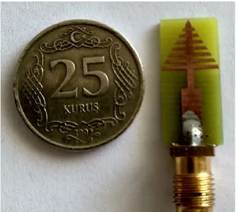
microstrip line with 3 mm length and 1 mm width is also positioned between the log periodic patch and the feed line to increase the impedance matching. In addition, the prototype of the proposed antenna was printed on a FR4 substrate with a tangent loss of 0.02 as seen in Figure 2.
49 (a) (b)
Figure 1: 2D view of proposed LPMA (a) top view (b) bottom view.
Figure 2: Photograph of the LPMA
2.1. Antenna Design Steps
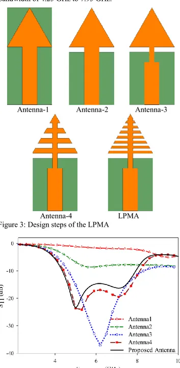
Several antenna designs were tried before the proposed LPMA was created. The design steps of the proposed LPMA are given in Figure 3, respectively. The simulated S11 graphs
of design steps are also shown in Figure 4. The antenna design is based on the equilateral triangular patch considering that it will be suitable for the log periodic antenna structure. First of all, the antenna feed line length of lf and width of wf were calculated respectively as 12mm and
3mm by the calculation tool of the IE3DTM program. While
calculating the equilateral triangular side length of a, it was thought that the triangular edge would be the longest element of the log periodic array.To calculating the length of the longest element of log periodic array, Equation (1) that given by [13] is used: max max
4
ra L
(1)where λmax is the longest wavelength of the antenna operating
frequencies in free space and εr is the dielectric constant of
substrate.
Since the longest wavelength in the C band frequencies is at 4 GHz, the side length of the equilateral triangular antenna is found as about 9mm. Thus, the design steps were started with a conventional ground plane and an equilateral triangular patch with 9mm side length fed by width of 3mm and length of 12mm microstrip line without impedance matching line. However, it was found that Antenna-1 was not suitable for C-band coverage.
Therefore, in order to increase the antenna's impedance matching at C-band frequencies; DGS, which is one of the impedance matching methods, was applied to the antenna ground plane. The length of the DGS (L) can be calculated by using equation from [14]:
min
4
effc
L
f
(2)where fmin is the minimum operating frequency, εeff is the
effective dielectric constant and c is speed of light in free space.
When fmin and εeff are taken as 4 GHz and 3.25, DGS length
of L is calculated as 10.5 mm according to Equation (2). Thus, by applying DGS to Antenna-2, the ground plane is reduced to approximately half in size. But, it has been found that the antenna is still unsuitable for C-band operations. Then, in the Antenna-3 geometry a thin microstrip line is inserted between the patch and the feed line, which is another impedance matching method. The length and width of this impedance matching line is determined by the optimization tool included in the IE3DTM program. Thus, a wideband
antenna structure having a bandwidth of 4.7-8.3 GHz and operating at 6.2 GHz resonance frequency was obtained. Thereafter, the antenna modified into a LPMA with 4 array elements to increase bandwidth for all C-band coverage in Antenna-4. Here, the triangular part at the upper end of the patch is also considered as a log periodic element. This antenna provided a very good coverage for the C band. However, it is desirable that the antenna operation band lower cut-off frequency approaches 4 GHz. Therefore, the number of log periodic array elements must be fully estimated. The total number of elements for the log periodic array is determined by [15]:
log(
)
1
log(1/ )
arB B
N
(3)where B is the bandwidth ratio, Bar is defined as the active
region bandwidth and τ is described as scaling factor. These parameters can be calculated from Equations (4-6) respectively: max min
f
B
f
(4) 21.1 7.7(1
) cot
arB
(5)50 1 n n
L
L
(6)where α is the half angle of antenna and Ln is the half length
of nth array element.
For an equilateral triangle, the angle α is 30° and τ is calculated as 0.87 from Equation (6). By using Equations (4) and (5), B and Bar are calculated as 2 and 1.325, respectively.
Finally, using the Equation (3), the number of log periodic array elements is calculated as 8. Thus, the proposed LPMA with consisting of 8 log periodic array elements was obtained According to simulated results proposed antenna has a almost whole C band coverage with the impedance bandwidth of 4.25 GHz to 7.95 GHz.
Antenna-1 Antenna-2 Antenna-3
Antenna-4 LPMA Figure 3: Design steps of the LPMA
Figure 4: Comparative simulated S11 graphs of the LPMA
design steps
3. Results and Discussion
The VSWR measurements of prototyped antenna was made by using the Keysight PNA 5224A Network Analyzer. The measured and the simulated VSWR results are given in Figure 5, comparatively. According to measurement and simulation results, the proposed LPMA has a very suitable bandwidth for C-band applications.
Figure 5: Measured and simulated VSWR graphs of the LPMA.
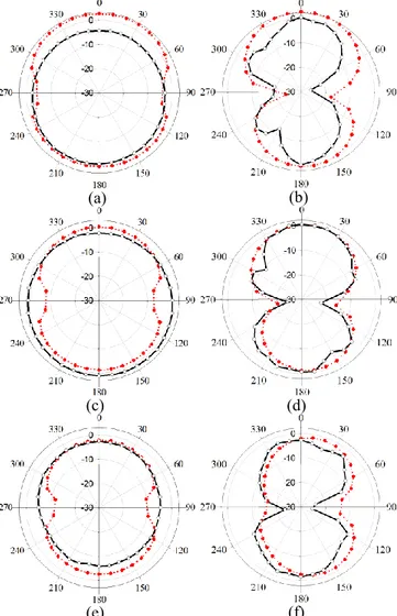
As can be seen from the Figure 5; although there is a great similarity between the IE3D and HFSS graphsthere are some differences between the measured and simulated results. There are 3 important factors affecting the difference between antenna measurement and simulations: SMA, soldering and substrate effects. Firstly, for small antennas like proposed LPMA, the SMA connector used to connect to the measurement equipment influences on the measurement results [16]. Secondly, one of the main concerns with small or high-Q antennas is the undesired soldering thermal loss in the conductor on the antenna substrate [17]. Finally, the parameters of the FR4 material obtained from the market are unstable according to the values used in the antenna designs. 2D radiation patterns of the proposed LPMA on xz-plane (ϕ= 0° or E-plane) and yz-plane (ϕ= 90° or H-plane) at the frequency points of 5 GHz, 5.8 GHz and 7 GHz are displayed in Figure 6. The pattern measurements are realized by using EBTRO EAMS-120 turn-table antenna measurement system. In figure 6, the red dotted lines ( ) show simulated gains while the black solid lines ( ) refer to measured gains.As can be seen from Figure 6, the measurement and simulation gain patterns for the LPMA are quite similar to each other for both the xz plane and the yz plane. From figure 6, the simulated maximum gains for xz-plane are 2.65 dB at 5 GHz, 0.34 dB at 5.8 GHz and -2.09 dB at 7 GHz; while according to the measurement results -0.51 dB, 1.09 dB and -2.5 dB gain values are obtained for same frequencies, respectively. Similarly, the maximum simulated gains for yz-plane are 2.67 dB at 5 GHz , 0.42 dB at 5.8 GHz and -2.06 dB at 7 Ghz; whereas, the measured gain values were obtained as 0.5 dB, 0.42 dB and -1.8 dB, respectively.
The simulated surface current distributions of the LPMA at the frequency points of 5 GHz, 5.8 GHz and 7 GHz are
51 presented in Figure 7. From the figure, the current distributions for given frequencies varies in similar. According to current distributions, the majority of the radiation concentrated on the log periodic elements and matching line. (a) (c) (e) (b) (d) (f)
Figure 6: Simulated and measured radiation patterns of the LPMA at (a) 5 GHz for xz-plane (b) 5 GHz for yz-plane (c) 5.8 GHz for xz-plane (d) 5.8 GHz for yz-plane (e) 7 GHz for xz-plane (f) 7 GHz for yz-plane
( shows simulations, shows measurements)
(a) (b)
(c)
Figure 7: Simulated current distributions of the LPMA at (a) 5 GHz (b) 5.8 GHz (c)7 GHz
3.1. Comparison with the Literature
Planar log periodic antennas can be considered as a suitable antenna for wideband wireless applications. However, wideband printed log periodic antennas are generally in dipole structure and have large dimensions. In [7], an UWB log periodic patch antenna with square fractal geometry is presented. Proposed antenna prototyped on Rogers RO4003 substrate with 3.55 dielectric constant and 173×70×1.52 mm3
overall size. In [8], a dual band log periodic microstrip patch antenna for 2.4 GHz and 5 GHz WLAN applications is designed on FR4 substrate with dielectric constant of 4.5, 1.6mm thickness and 0.019 tangent loss. The antenna consists of 4 inset fed microstrip patches with the overall dimensions of 120×75 mm2. In [9], a wideband microstrip antenna based
on log periodic technique with 270×110 mm2 entire size was
conceived and demonstrated on FR4 substrate which operates between 2.3-6 GHz frequencies according to VSWR results. A 117×35 mm2 sized coplanar waveguide fed printed log
periodic dipole array (LPDA) is presented in [10]. The proposed antenna has a wide bandwidth from 3 to 6 GHz and manufactured on ARLON AD450 with dielectric constant of 4.5, thickness of 1.524mm and tangent loss of 0.0035. Wideband log periodic microstrip antenna dimensions are relatively large since only the frequency-dependent log periodic antenna equations are used for dimension calculation of array elements. In this study, DGS equation of the triangular patch antennas is also used for the dimension reduction in addition to the log periodic array equations. Thus, the proposed LPMA dimensions are considerably reduced compared to the other log periodic microstrip antennas in the literature [7-10]. The comparative results of the proposed LPMA with the other wideband log periodic microstrip antennas in the literature [7-10] are given in Table 1. According to the table, the proposed LPMA stands out for its small size and the wide bandwidth, compared to other wideband log periodic antennas in the literature. As mentioned before, two different methods were used to achieve this size reduction. One of these methods is the use of monopole log periodic elements instead of dipole; the other was to use the defected ground structure.
52 Table 1: Comparison of the LPMA with wideband log periodic printed antennas given in literature
Reference Antenna size (mm) Frequencies (GHz) Operating
7 173×70 3.1-10.6 8 120×75 2.41-2.49 5.0-5.45 9 270×110 2.3-6.0 10 117×80 3.0-6.0 LPMA 19.8×9 4.25-7.95
4. Conclusions
In this study, a novel wideband microstrip antenna with triangular shaped log periodic patch is presented for C-band applications. The proposed microstrip log periodic monopole antenna (LPMA) has a very compact size compared to other log periodic antennas in the literature with total dimensions of 9×19.8 mm2. The proposed antenna is designed and
prototyped on a FR4 substrate with 4.3 dielectric constant, 0.02 tangent loss and 1.6 mm thickness. The proposed LPMA has 4.25-7.95 GHz frequency bandwidth by simulations, while it operates between 4.7-7.5 GHz frequencies according to measurements. It was observed that both the simulation and the measurement results, antenna has a resonance frequency at 5 GHz. For this reason, it is clear that the proposed LPMA is a suitable antenna for almost all C-band applications, particularly for the 5 GHz Wi-Fi and 5.8 GHz ISM band applications.
References
[1] The Institute of Electrical and Electronics Engineers (IEEE), IEEE Std 521-2002: Standards Letter Designations for Radar Frequency Bands, New York, 2002.
[2]
Federal Communications Commission, First report and order, Revision of Part 15 of commission’s rule regarding UWB transmission system FCC 02-48, Washington, 2002.[3]
C.A. Balanis, Antenna Theory: Analysis and Design. John Wiley & Sons, New Jersey, 2005.[4]
R. Garg, P. Bhartia, I. Bahl, and A. Ittipiboon, Microstrip Antenna Design Handbook. Artech House, Boston, 2001. [5] P.A. Ambresh, P.M. Hadalgi, and P.V. Hunagund, Planarmicrostrip slot antenna for S & C band wireless applications, Journal of Physics: Conference Series, 435(1):12-22, 2013.
[6] J.A. Ansari, S. Verma, M.K. Verma, and N. Agrawal, A novel wide band microstrip-line-fed antenna with defected ground for CP operation, Progress In Electromagnetics Research, 58: 169-181, 2015.
[7] A. Amini, and H. Oraizi, Miniaturized UWB log periodic square fractal antenna, IEEE Antennas and Wireless Propagation Letters 14: 1322-1325, 2015.
[8] S.A. Nasir, S. Arif, M. Mustaqim, and B.A. Khawaja, A log periodic microstrip patch antenna design for dual band operation in next generation Wireless LAN
applications, IEEE 9th International Conference on Emerging Technologies (ICET), Islamabad, Pakistan, 2013.
[9] H.G. Foshtami, H.A. Talkhouncheh, and H. Emami, Wideband log periodic microstrip antenna with elliptic patches, Journal of Information Systems and Telecommunication, 1(2): 113-117, 2013.
[10] G.A. Casula, P. Maxia, G. Montisci, G. Mazzarella, and F. Gaudiomonte, A printed LPDA fed by a coplanar waveguide for broadband applications, IEEE Antennas and Wireless Propagation Letters, 12: 1232-1235, 2013. [11] HyperLynx®3D EM, IE3DTM Version 15, Mentor
Graphics, Wilsonville, 2015.
[12] Ansys, HFSSTM Versiyon 15, ANSYS Corporation
Software, Pittsburgh, 2014.
[13] C. Yu, H. Wei, C. Leung, Z. Guohua, Y. Chen, Q. Wei, and K. Zhenqi, Ultrawideband printed log periodic dipole antenna with multiple notched bands, IEEE Transactions on Antennas and Propagation, 59(3): 725-732, 2011.
[14] K. Saxena, Comparison of rectangular, circular and triangular patch antenna with CPW fed and DGS, International Journal of Electronics & Communication Technology, 7(3): 138-141, 2016.
[15] R. Carrel, The design of log periodic dipole antennas,
IEEE IRE International Convention Record
Proceedings, 9:61-75, 1966.
[16] B.S. Yarman, Design of Ultra-wideband Antenna Matching Networks: Via Simplified Real Frequency Technique. Springer Science & Business Media, 2008. [17] P. Bahramzy, O. Jagielski, and G.F. Pedersen, Thermal
loss and soldering effect study of high-Q antennas in handheld devices. 7th European Conference on Antennas and Propagation (EuCAP), 2013.