T.C.
ALTINBAŞ UNIVERSITY
Institute of Graduate Studies
Mechanical Engineering
A MODEL FOR THE DISTRIBUTION OF
TEMPERATURE ON THE ALUMINUM ALLOY
WHEN USING FRICTION WELDING
Sewara Mohsin Mahealdeen SHEKHAN
Master Thesis
Supervisor
Asst. Prof. Dr. Hakan KAYGUSUZ
A MODEL FOR THE DISTRIBUTION OF TEMPERATURE ON
THE ALUMINUM ALLOY WHEN USING FRICTION WELDING
By
Sewara Mohsin Mahealdeen SHEKHAN
Mechanical Engineering
Submitted to the Graduate School of Science and Engineering in partial fulfillment of the requirements for the degree of
Master of Science
ALTINBAŞ UNIVERSITY 2020
iii
The thesis titled “A MODEL FOR THE DISTRIBUTION OF TEMPERATURE ON THE ALUMINUM ALLOY WHEN USING FRICTION WELDING” prepared and presented by SEWARA MOHSIN was accepted as a Master of Science Thesis in Mechanical Engineering.
Asst. Prof. Dr. Hakan KAYGUSUZ Supervisor
Thesis Defense Jury Member
Asst. Prof.Dr. Hakan KAYGUSUZ
School of Engineering and Natural Sciences,
AltinbasUniversity __________________
Asst. Prof.Dr. İbrahim KOÇ
School of Engineering and Natural Sciences,
AltinbasUniversity __________________
Asst. Prof.Dr. Bengi ÖZUĞUR UYSAL
Faculty of Engineering and Natural Sciences Kadir Has
University __________________
I certify that this thesis satisfies all the requirements as a thesis for the degree of Master of Science.
Approval Date of Institute of Graduate studies __/__/__
iv
I hereby declare that all information in this document has been obtained and presented in accordance with academic rules and ethical conduct. I also declare that, as required by these rules and conduct, I have fully cited and referenced all material and results that are not original to this work.
v
DEDICATION
I would like to dedicate this work to my first teacher, my mother, my first supporter and role model, my father and my companion throughout the journey. Without you, this dream would never come true and to my brother and my sister who stood with me in order to achieve my dream.
vi
ACKNOWLEDGEMENTS
I would like to express my sincere gratitude to all the instructors that have taught me more than just science, especially my supervisor Asst. Prof. Dr. Hakan KAYGUSUZ, for all the time, support and guidance provided to me along the journey to accomplish this work. Thank you all for all the knowledge and advice that made me overcome all the difficulties that I have faces.
vii
ABSTRACT
A MODEL FOR THE DISTRIBUTION OF TEMPERATURE ON THE
ALUMINUM ALLOY WHEN USING FRICTION WELDING
SHEKHAN, SEWARA MOHSIN MAHEALDEEN M.S. Mechanical Engineering, Altınbaş University,
Supervisor: Asst. Prof. Dr. Hakan KAYGUSUZ Date: June / 2020
Pages: 80
Aluminum alloys are characterized by high hardness and high corrosion resistance are used in the construction of various aircraft structures and in spare parts for these aircraft. As a result, these parts need to be bonded between them and from the linking processes by welding method, especially friction stir welding (FSW).In this study, aluminum alloy parts (2024-T6) were used and welded by friction stir welding method. Three types of tool were used (square, triangular and conical) and four rotational speeds were used for the welding tool and three linear speeds for the vehicle that carries the models that it is welded, and temperature distribution has been studied on the surfaces of the models when welding operations are conducted in order to study its distribution on the parts during welding and its effect on tensile strength. Also, a mathematical model was created for welded parts, and these mathematical models were solved using the specified finite elements method through the use of the ANSYS-15.0 program, as well as models for the purpose of testing the tensile strength of all variables. The results of the tests indicate that the distribution of temperatures on the surfaces of the welded models in an acceptable match with the results obtained from the mathematical model, for the mathematical model is of great importance in showing the distribution of temperatures in and around the welding area. The results show that the temperatures generally increase with increasing the rotational speed of the welding tool while decreasing with increasing linear velocity of the welding table. The results also indicate an increase in the flap by increasing the rotational speed of the welding tool and decreasing by increasing the linear velocity of the welding table. The amount of heat traveled from the welding area to the rest of the model increases by increasing the rotational speed of the welding tool and also by increasing the linear velocity of the welding
viii
table when the welding process is performed. Among the results of tensile strength tests is a variation that the welding efficiency decreases with an increase in the rotational speed of the welding tool slightly.
Keywords: Aluminum alloys, friction stir welding, rotational speed, travel speed, tensile strength.
ix
TABLE OF CONTENTS
PAGEDEDICATION... v
ACKNOWLEDGEMENTS ... vi
ABSTRACT ... vii
LIST OF FIGURES ... xi
LIST OF TABLES ... xiii
1 INTRODUCTION... 1
1.1 FRICTION WELDING ... 1
1.2 TECHNIQUES OF FRICTION PROCESSES ... 3
1.2.1 Advantages of Conflicting Mixing Process ... 4
1.2.2 Environmental Benefits ... 4
1.2.3 Power Benefits (Energy Benefits) ... 5
1.2.4 Other Advantages... 5
1.2.5 Disadvantages of Conflicting Weldings ... 5
1.3 LIMITATIONS OF THE CONFLICTING MIXING PROCESS ... 5
1.4 THE PROCESS OF STIR FRICTION WELDING ... 6
1.5 FRICTION STIR WELDING ... 7
1.5.1 Benefits of Conflicting Stir Welding ... 8
1.5.2 The principle of Friction Mixing Welding... 8
1.5.3 Microstructure of the Welding Zone... 9
1.5.4 Conflicting Welding Agents ... 9
1.5.5 The Disadvantages of the Process of Welding of Confocal Mixing ... 10
1.5.6 Specification of the Tool Used in the Process of Mixing the Friction and the Welding of the Mixing of Friction ... 11
1.6 ALUMINUM AND ITS ALLOYS ... 12
1.6.1 Classification of Aluminum Alloys ... 12
1.6.2 Welding of Aluminum and its Alloys ... 13
1.7 TEMPERATURE DISTRIBUTION & MATERIAL FLOW DURING FRICTION STIR WELDING ... 14
x
1.7.2 The Influence of Tool Rotation Speed ... 16
1.7.3 Effect of Parameters on the Size of the Stir Zone ... 16
1.8 THE GOAL OF THE RESEARCH ... 18
2 LITERATURE REVIEW ... 19
3 EXPERIMENTAL WORK ... 28
3.1 METAL PROPERTY ... 28
3.2 FRICTION MIX WELDING (FSW) ... 29
3.2.1 Distributing Temperatures When Performing Friction Mix Welding ... 31
3.3 THE MATHEMATICAL MODEL FOR TEMPERATURE DISTRIBUTION ………..33
3.4 TENSILE TESTING ... 33
3.4.1 Tensile Test Models ... 34
4 RESULTS AND DISCUSSION ... 35
4.1 DISTRIBUTING THE DEGREE OF HEAT TO THE SURFACES OF WELDED PATTERNS ... 35
4.2 THE EFFECT OF FRICTION MIX WELDING PROCESS ON MECHANICAL PROPERTIES ... 54
4.2.1 Tensile Test ... 54
5 CONCLUSION ... 59
xi
LIST OF FIGURES
PAGEFigure 1.1: FSW applications in different fields. ... 2
Figure 1.2: Techniques of the friction process... 3
Figure 1.3: Process Steps for Conflicting Mixing. ... 6
Figure 1.4: A temperature contours on transverse section for welding speed of a- 20 mm/min b- 40 mm/min & c- 60 mm/min. Shouldar welding = 17.5 mm, tool rotation speed = 900 rpm. ... 14
Figure 1.5: A temperature contours on transverse section, a- 900 rpm, b- 1050 rpm & c-1200 rpm. Welding speed = 20 mm/min and shouldar welding = 17.5 mm. ... 14
Figure 1.6: A contour schemes of viscosity at tool rotation speed of, a- 900 rpm, b- 1050 rpm & c- 1200 rpm, welding speed = 20 mm/min, shouldar welding = 17.5 mm ... 15
Figure 1.7: A contour schemes of viscosity at shouldar welding of, a- 15 mm, b- 17.5 mm & c- 20 mm. Welding speed =20 mm/min, tool rotation speed =1050 rpm... 17
Figure 1.8: A contour schemes of viscosity at welding speed of, a- 20 mm/min, b- 40 mm/min & c- 60 mm/min. tool rotation speed =1050 rpm , shouldar welding =17.5 mm ... 17
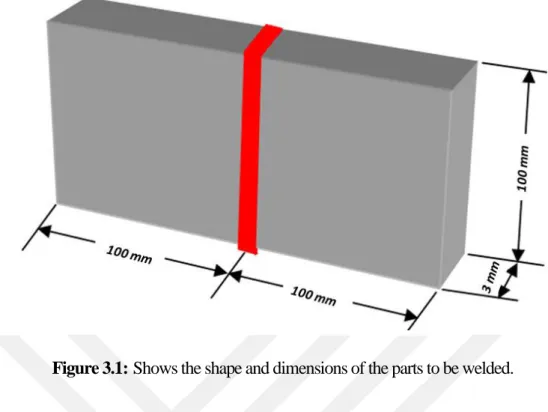
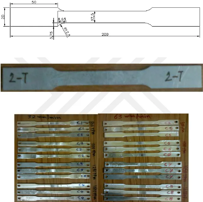
Figure 3.1: Shows the shape and dimensions of the parts to be welded. ... 30
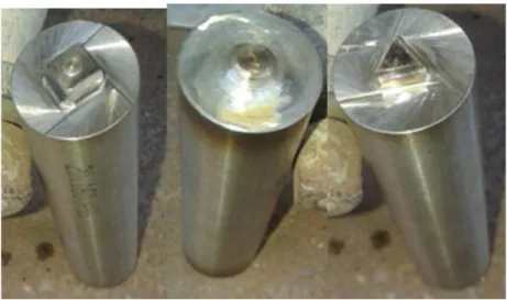
Figure 3.2: Shows the shape and dimensions of the welding tools: (left-a) - cylindrical tool with a square pin; (middle-b) - a cylindrical tool with a conical pin; (right-c) - Cylindrical tool with a triangular pin. 31 Figure 3.3: Shows the pieces after welding (right-a) welding with a cylindrical tool with a square protrusion. As for (left-b) welding with a cylindrical tool with a serrated conical protrusion. ... 31
Figure 3.4: Shows the points where the temperatures were measured for the models. ... 32
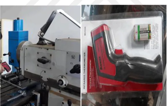
Figure 3.5: Shows device those measurers the temperature by distance.. ... 32
Figure 3.6: The mathematical model of temperature distribution.. ... 33
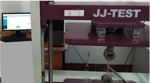
Figure 3.7: Tensile strength testing device.. ... 33
Figure 3.8: Shows the shape and dimensions of the test sample to check the tension of the base metal and welds... 34
Figure 4.1: Shown results of the Cylindrical tool, Square pin of Dof Solution, Nodal Temperature. ... 41
Figure 4.2: Shown results of the Cylindrical tool, Square pin of Thermal flux, Thermal flux vector sum.. ... 43
Figure 4.3: Shown results of the Cylindrical tool, Square pin of Element solution, Head flow. ... 45
Figure 4.4: Shown results of the Cylindrical tool trangle pin of Dof Solution, Nodal Temperature ... 46
xii
Figure 4.5: Shown results of the Cylindrical tool trangle pin of Thermal flux, Thermal flux vector sum.. ... 48 Figure 4.6: Shown results of the Cylindrical tool trangle pin of Element solution, Head flow.. ... 50 Figure 4.7: Shown results of the Cylindrical tool cone pin of Dof Solution, Nodal Temperature. ... 51 Figure 4.8: Shown results of the Cylindrical tool cone pin of Thermal flux, Thermal flux vector sum... ... 53 Figure 4.9: Shown results of the Cylindrical tool cone pin of Element solution, Head flow. . 54 Figure 4.10: Diagram showing stress tests - engineering strain of several aluminum alloy models (2024-T6) for the base metal. ... 55 Figure 4.11: Stress Ratio Diagram - Engineering Strain of Aluminum Alloy (2024-T6) for base metal. ... 55 Figure 4.12: Stress Ratio Diagram - The true strain of the aluminum alloy (2024-T6) for the base metal... 55 Figure 4.13: Comparison of the stress ratio diagram - the engineering and true strain of the aluminum alloy (2024-T6-) of the base metal. ... 56 Figure 4.14: A chart showing the method for calculating the steel coefficient of aluminum alloy (2024-T6) for the base metal. ... 56 Figure 4.15: Shows the tensile inspection patterns for the base metal and welded connections of the alloy (2024-T6). ... 59
xiii
LIST OF TABLES
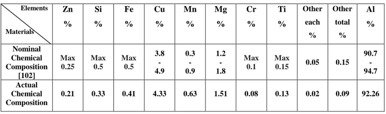
PAGETable 3.1: The Chemical Composition of Aluminum Alloy (AA 2024-T6). ... 28
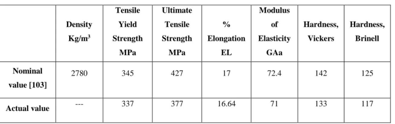
Table 3.2: Mechanical Properties of Aluminum Alloy (AA 2024-T6). ... 29
Table 4.1: Shows the Distribution of Temperatures During the Welding Process on the Models. ... 36
Table 4.2: Shows the Distribution of Temperatures During the Welding Process on the Models. ... 37
Table 4.3: The Value of the Passive Hardening (n) and the Resistance Coefficient Value (k) for the Aluminum Alloy (2024-T6). ... 56
1
1 INTRODUCTION
1.1 FRICTION WELDING
That the properties of aluminum, which made its use widely in all fields of industry is light weight compared to other types of minerals. It is an engineering material that follows steel with a density of about one-third of the steel density. High resistance is obtained in heat-treated aluminum alloys, which makes the use of these alloys very convenient in the manufacture of aircraft, sea and motor vehicles, it is one of the most abundant metals in the earth's crust. Its third ranking is among the elements available in the Earth after oxygen and silicon, with 7.5 to 8.1% of the Earth's surface weight, one of the most chemically effective metals [1, 2].
Aluminum alloys are also resistant to corrosion due to natural climate factors, as heat-treated aluminum alloys have the ability to resist corrosion with water, salts and other elements. The superior aluminum ability is resistant to corrosion because of the high affinity of the union with the oxygen element and the formation of a thin surface Non-permeable oxide (Al2O3) formed
when the metal is exposed to the air to protect it from corrosion, so it is used in the manufacture of tanks for the chemical industries, as well as in the manufacture of dyes and uses powder in the paint as well as all those properties For aluminum, aluminum is a non-toxic metal so it is used in the manufacture of cans for food and soft drinks [2, 3].
The mechanical bonding of these alloys has added additional weight and cost to the aircraft, but now almost 70% of the previously used brushes are reduced and comtoolsated by Friction Stir Welding [4].
Friction Stir Welding, which is called in some sources, is a new technique for solid state welding, which means that the metal does not reach the melting point during the welding process. This technique was first discovered in 1991 at the Welding Institute / University of Cambridge in the United Kingdom. [5,6] (TWI) This technique was first used in aluminum alloy welding and then began to spread in the last few years to be used in welding other metals, Good bonding technique is an important technique especially for aluminum alloys that have low welding ability in fusion welding methods such as MIG (TIG) shielding and laser welding such as some alloy chains (xxx, 7xxx6xxx, 2) and can be used This method is also used in the welding of different metals in the chemical composition of Dissimilar Materials [5, 7-9]. The most important problems of the refractory welding of the alloy (AA2024-T6) is due to the reduction in the tensile strength of these alloys after the welding process due to the increase of Grains Growth due to the amount of high heat entering the welding area, leading to a decrease
2
in the value of hardness and the occurrence of a series of metallurgical changes in the affected area (HAZ) during and after the welding process and the occurrence of cracks in the welds such as hardening cracks and very fine cracks in the molten part of the heat-affected area [10, 11].
The friction welding is produced by using a non-extooldable welding tool used to soften the piece to be welded through friction heat and Plastic Deformation, allowing the tool to mix and mix the two pieces of material to be sold [12].
FSW operations are used in the following industries [13].
a. In the automotive industry, road transport vehicles and agricultural machinery. b. Shipbuilding and Marine Industries.
c. Aviation Industry d. High-speed trains e. Railway industry f. Construction industry g. Electrical Industries
h. In the manufacture of pipes and heat exchangers i. Spacecraft
j. Flat and cylindrical fuel tanks and bulk liquids containers k. Rocket fuel tanks and military industry.
3
1. It has been proven that the welding of the confection is an effective bonding technique for various types of materials, including metals and polymers.
2. The confocal mixing process has been expanded to include a wider range of fine-tuning, variable casting, powder processing, modification of the microstructure and the manufacture of metal molded compounds based on the basic principles of the molybdenum welding process. Another area in which the advantages of the fuzzy mixing process appear is the creation of ultra-plastic materials [14-15].
3. Areas chosen on the surface of the structural structure can be treated thermally and mechanically using the confocal mixing process and with a depth of more than 25 mm to reinforce certain qualities [16-18].
1.2 TECHNIQUES OF FRICTION PROCESSES
It is universally known that heat generated from friction can be used to bind and process materials. The number of techniques that rely on friction as a basis for their work has increased so that friction processes can be used on complex forms and products on a large scale [19, 20], Figure (1.2). For example, friction can be applied to different types of non-round composite forms using non-circular, rotational, linear and frequency compounds at an angle [21, 22].
4
In practice, all these welding techniques are considered as one shot, where the bonding process takes place more or less at the same time. Therefore, the greater the area of the section to be attached to the solder, the greater the force used in the welding process is relatively monopolistic and absolute, and becomes what is called in practice "prohibited".
1.2.1 Advantages of Conflicting Mixing Process Mineral advantages are as follows [15]:
Steel phase process. Less distortion.
Good dimensional stability and repeatability.
The connecting area and the occupied area are characterized by excellent mechanical properties.
Microscopic structure that is crystallized and soft. No loss of alloy elements.
No cracks due to stiffness.
Replace weak parts bonded with strong parts.
Used in the welding of all aluminum alloys and alloys which are generally classified as non-weldable by fissile welding processes (e.g. 2xxx and 3 xxx aluminum alloy patterns), which give high quality friction welding.
Post-weld modulation by mixing with friction.
The depth of the surface layer is classified by process criteria or by a probe design which can be used by pin or without pin.
1.2.2 Environmental Benefits
Do not need to wear a gas mask during welding. Requires simple surface cleaning.
There is no waste from the grinding process because it is not needed. Do not need cooling liquids to reduce heat.
Non-consumption of materials during welding such as welding wires, protective clothing for welding or any other gases used in welding.
5 1.2.3 Power Benefits (Energy Benefits)
Good selection of materials used (eg, linking different metals to fish) leads to weight reduction.
Only need about (2.5%) of the energy used in laser welding.
Low fuel consumption in lightweight aircraft, vehicles and vessels used. 1.2.4 Other Advantages
Other non-classified advantages are listed below [16, 17]: There is no need to process or prepare the welding area.
Do not need to be scrubbed, polished or grinded in high productivity laboratories.
It has the ability to weld aluminum and copper with a thickness of more than (75 mm) in two halves.
There is no ultraviolet radiation.
The welding process is easy to program and requires limited training for welding workers. Its ability to bind two metals with two different thicknesses.
1.2.5 Disadvantages of Conflicting Welding’s
Besides the advantages, disadvantages are also possible. These can be listed as below [23]: The operator needs a fixed handle.
Need arm support.
Need post-welding operation.
1.3 LIMITATIONS OF THE CONFLICTING MIXING PROCESS
Can be listed accordingly [26]:
1. Major challenges such as the design of tools and continuous ores limit the use of the two processes in manufacturing, especially in the manufacture of alloys with high melting points or high-strength alloys.
2. It is not impossible to weld all aluminum structures by the process of mixing and taking advantage of solid state features. For example, large structures, hard-to-reach areas and large thickness plates are difficult to connect using friction welding.
3. It is important to use force down and cross-force and therefore must use very powerful machines
4. The welding machines are characterized by the fact that they are not flexible even when these machines are developed and automated in recent years.
5. The length of the wedge (wire, pin) in the fixed machine does not detoold on the thickness of the plate in question
6
1.4 THE PROCESS OF STIR FRICTION WELDING
Used in the process of welding the mixing of friction welding tool rotary non-fusion of a cylindrical shape called shoulder or shoulder, which is the main source of heat generation resulting from friction and plastic deformation, which at the bottom end of the Probe or Pin stirs gradually in the contact area of the plate (5, 7, 11). The stitching process continues until full contact is achieved between the bottom surface of the welding tool and the top surface of the plates to be welded. After the sutures are completed, the plates to be welded are moved by a linear motion to a tool that leads to the completion of the binding process along the welding line [5, 6]. As shown in Figure (1.3).
7
One of the most important factors for the welding of friction is the change in the rotational speed of the tool and the speed of the linear (Travel Speed). The movement of the rotary welding tool involves the mixing and mixing of the metal around the stitching. The linear motion, which is a transition of the metal relative to the welding tool, moves the metal mixed in front to the back of the sutures and the welding process [28, 29]. The movement of the high-temperature rotary welding tool generates high heat as a result of friction with the metal, thus mixing and mixing the metal. The rotational velocity of the welding tool has an effect on the welding temperature. The higher the rotary speed of the welding device, the higher the maximum temperature of the welding area. [30, 31] The linear speed of the weld also affects the amount of heat entering the welding area along the welding line. Decrease when linear speed increases [5].
The use of alloy (AA 2024-T6) in many areas as mentioned above increases the importance of the study of the effect of the factors of welding mixing friction, the rotational speed of the welding tool and linear speed of welding on the mechanical properties and internal structure of the welded joints of this alloy.
1.5 FRICTION STIR WELDING
Friction welding is generally the process of binding materials to each other using friction heat as well as pressure, and bonding occurs at contact points. This process is often used as a large-scale commercial operation in many countries and in various industries in the world. [32]. The importance of friction welding in the possibility of welding a lot of materials, especially Dissimilar materials, which differ in thermal properties, chemical and mechanical, and the difficulty of welding other methods, as well as the speed of delivery and low cost and high quality of the joints. [33] The process of welding is a monopolistic methods used in Mass Production and production on The formation of batches and the production of welding links of ferrous materials. [34] The heat generated by friction is also the only source of thermal energy in this process. The mechanical energy is converted to thermal energy so that the latter can be used for heating events The process begins with the rotation of one of the parts of the operator while the other part is fixed as the surface of the surface heated as a result of the friction generated between the two surfaces to be sold, then the process of welding and adhesions at certain points called fragments and then collapse, and continue the process until the temperature is sufficient for Plastic flow is then stopped and the pressure is pressed steadily. The metal is welded and the welding process takes place with the formation of a perimeter collar called flash metal around the welding area. The welding process is performed in several
8
ways detoolding on the equipment used and the geometry of the section to be sold, which is one of the determinants of this process as they are more suitable with circular shapes [35]. 1.5.1 Benefits of Conflicting Stir Welding
Mixture welding is an important method for welding aluminum alloys, especially low-impact aluminum alloys for welding in fusion welding methods such as alloy series (2xxx, 7xxx) [36]. There are a range of advantages of mixing mixtures compared to other conventional welding types:
1. . It needs a little energy during the welding process. 2. It takes a relatively short time during the welding process. 3. The temperature of the welding area is relatively low.
4. The welded metal is exposed to a small amount of distortion.
5. Since welding is done in solid state, it does not contain defects such as porosity. 6. Most kinds of alloy can be welded in this way.
7. Do not use the Filler Metal method during the welding process and a little distortion compared with the arc welding.
8. The method of welding is clean because it does not use inert gases as a protective cover during welding and does not use a smelting assistant and no smoke or poison gases arise during the welding process. It is therefore environmentally friendly so it is called Green Technology [36-38].
1.5.2 The Principle of Friction Mixing Welding
The principle of welding or mixing of friction in the process of welding without melting the pieces to be sold as in the case of fusion welding, and the highest temperature may reach the metal does not exceed (80%) of the melting point of the metal to be sold [36].
The process of connecting this method is done by using a non-fusion rotary welding tool with a cylindrical shape called the bearing and at its lower end a stump for stitching is gradually inserted into the contact area of the plates to be soldered and the stitching process continues until full contact is achieved between the bottom surface of the welding tool and the upper surface of the plates to be welded [39].
The welding tool has three advantages: First, heating the pieces to be welded, secondly, thirdly, stirring and mixing the metal to be welded, resulting from the rotational movement of the stitching and stitching, resulting in metal deformation of the metal, as well as the containment and containment of the hot metal under the welding armrest [39-41].
9
The heat generated in the pieces to be welded is due to the friction between the stitches of the stitching and the position of the welding tool on the one hand and the pieces to be welded on the other, as well as the result of the plastic deformation occurring in the pieces to be soldered. This heat helps to soften the metal around the stitching of the sutures. To move the soft metal in front of the stitches of the stitches to the back, which leads to fill the vacuum or hole that was formed by the welding tool previously. After the completion of the process of stitches and heating are moving the plate’s linear movement relative to the tool and this leads to the completion of the process of binding along the welding line [39-41].
1.5.3 Microstructure of the Welding Zone
The microstructure produced by the welding of the confocal mix detoolds on a number of factors, including the chemical composition of the components of the chemical composition and the type of tempering or normalization the alloy as well as welding parameters, as speed of rotation of the tool and linear speed of welding and some other engineering factors Such as the shape and design of the welding tool and the type of metal backing plate on which the pieces are to be welded [41-43].
1.5.4 Conflicting Welding Agents
There are two factors that can be controlled to obtain quality in welding and thus obtain acceptable mechanical properties. These include:
1. Geometric Parameters: such as welding tool design, metal type welding tool as well as the form of extrusion stitches and latch [46-50].
2. Process Operators Parameters: The rotational velocity of the welding tool, the linear speed of the welding table, the angle of the welding tool, the depth of the extrusion of the stitching and the vertical force attached to the welding area [46-50]. Axial Load has a direct impact on the quality and properties of mechanical welding and plays an important role during the welding of the friction mix as the degree of metal mixing and dispersion detoolds on the vertical force exerted as well as the welding temperature [51].
10
1.5.5 The Disadvantages of the Process of Welding of Confocal Mixing
Corridor defects: Sometimes when using insufficient welding grades, either due to high transverse velocity or slow rotational speed, for example, the welded metal is unable to adjust the large distortion of the weld. This in turn may cause the widening of the defects of the corridor and its continuation along the welding line, which may appear on the outer shell or surface of the weld. The instrument used may be limited to low temperatures and this leads to the non-continuity of binding between the materials on both sides of the welding line [18]. Link kissing: The reason for this label is due to the simple contact of the welded material. According to a study by Terry Khaled [54], kissing is a descriptive expression of two very close surfaces, but not enough to make the majority of the coarse grains of the first surface possess enough distortion to affect the formation of atomic bonding. This kind of defect is most often an obstacle because of the difficulty of detecting it using non-destructive methods, for example, X-ray or ultrasound scans [18].
No tooletration: If the tool rises away from the operator or the pin is not high enough, the interference at the lowest point of welding may not be exposed to the grounding and cracked due to the use of the welding device causing no distortion resulting from the tooletration of the pin. This is most often a click in the material, which may be a strong source of corkscrews [18]. Wormhole: This hole is near the lower welding area due to the use of a constant rotary speed and high linear speed. Moreover, the size of the aperture increases with linear velocity due to insufficient metal melting at the bottom of the welding area. There are indications that the ratio of linear velocity to rotational velocity is an important factor in the formation of a defect type, which is called a worm house. A high proportion tends to form worm-like defects for the same material and the same tool design. Most of the heat generated at the contact area between the welding device and the operator is shown. The heterogeneity of the heat generated in the contact area of the tool with the operator may cause defects in the form of excessive flash due to overheating of the surface [19].
Small cracks: Some defects can be observed at the bottom of AS. These defects do not appear in the form of apertures or aisles, but in the form of molecular clusters or small gaps This type of defect can be observed only in the upper block in the case of soldering The spindle in which the linear motion is opposite to the rotary direction of the welding tool, so that the tool is regularly overlapped to operate the surface, results in a true fusion of the area. [47] The reliance on the weld shoulder design and the clearance angle of the tool is necessary to make an appropriate amount of plastic material Mixing, and thus control welding properties. [48]
11
1.5.6 Specification of the Tool Used In The Process of Mixing the Friction and the Welding of the Mixing of Friction
The tool used for welding of the friction mixture usually contains two main parts: the cylindrical shoulder and the protrusion, which in turn has a smaller diameter. Experiments were carried out to calculate the generated heat and the force exerted during the welding process by mixing with various forms of welding tools. [55] The distortion caused by friction by the motion of the welding tool increases the temperature of the aluminum to the state where it is semi-solid but retains its steel system. The advantages of the welding process were observed in the mixing of friction due to the development of the welding tool design and the improvement of the factors that affect the welding process [56]. The study examined the superior advantages of this type compared to arc welding by connecting aluminum alloys such as alloy series (2xxx, 6xxx, 7xxx). These aluminum alloys (non-weldable) are used as fusion welding.
In a study conducted by Mishra and Ma, the temperature of the friction welding solder was compared with the heat required for fusion or arc welding techniques. Thus, the inlet heat generated in the friction welding is distributed to the largest possible area of the bonding area. This in turn leads to a low tension and deformation link due to low temperature and welding temperatures. Fusion welding has high temperature and welding grades, which in turn leads to the melting of the bonding area and the bonding or bonding process. The effects of extrusion were analyzed through several studies, where the optimal state of the instrument was found to have significant changes in the strength used and the quality of the welding during the welding process. Estimates of the contribution of axial forces during the welding process were arranged from 51% to 2% based on studies [55]. The ideal shape of the protrusions observed was square. These data were the most perfect through a matrix of wide factors used in various tools, including a triangle and a square non-serrated and the same species with teeth.
Flow around the welding device was described as a distinct area of three separate flow systems [58]. Three non-pressurized runoff areas were observed to form a cyclic buffer during the welding process of an alloy (AL-Li 2195). A small amount of lead was placed in the connecting line. The microcellular pathway was analyzed using x-ray of the models after the welding process. It was found that this flow was caused by teeth or other elements on the pin (extrusion). It was easy to observe the vertical flow by welding using the same gear in both directions during successive movements and observing the material flow up towards the pin and showing a flash on the surface. This in turn also serves to generate visible aggregates that can be detected simply through the entire welding block in the material
12
1.6 ALUMINUM AND ITS ALLOYS
Aluminum and its alloys are used in many industrial applications because of their good physical and chemical properties. The aluminum in its pure metallic form is soft and soft, with a hardness of 40 degrees on the Bernel scale. The aluminum resistance to the tensile strength is weak, with no more than 900 N / mm2 after its polymerization. Aluminum is used as an alloy in tensile strength on most applications Industrial. The most important aluminum alloys are aluminum, brass, aluminum, brass, magnesium, aluminum, manganese, aluminum, silicon, aluminum and zinc.
The mechanical properties of aluminum can be improved by adding alloying elements. These elements are mainly added to improve mechanical properties such as Tensile Strength, Hardness, Machinability, Toughness and sometimes Fluidity, and some required properties in plumbing. These elements are magnesium (Mg), zinc, Cu, manganese, nickel, silicon, Ti and some other elements, as follows:
1. Add copper to increase tensile strength, which is usually low in pure aluminum and also to improve operability.
2. Manganese is added to improve tensile strength and resistance against corrosion. 3. Add silicone to improve the properties of plumbing, where it is difficult to fabricate the
pure aluminum due to the increase in the value of Surface Tension Valsilkon aluminum is gaining high flow during the plumbing process as well as the improvement of some other mechanical properties.
4. Magnesium is added to increase tensile strength more than manganese, as well as improve corrosion resistance with seawater, so magnesium-magnesium alloys are widely used in ship and boat construction.
1.6.1 Classification of Aluminum Alloys
In general, aluminum alloys can be divided into two main parts: Wrought Alloy and Caste Alloy. Wrought Alloys are formed in either Rolling, Extruding, Drawing or Forging. Cast aluminum alloys are produced either by sand casting or die casting. In general, 85% of the used aluminum alloys are mechanically alloyed alloys.
Most commercially available aluminum alloys are classified according to BS1470 / 1475 for British alloys (BS 1490) for cast alloys, or are classified according to the specifications of the American National Standardization Institute (ANSI) according to H35.1 and H35. 2) and by the main alloy element added to the alloy [60].
Some cast aluminum alloys can improve their mechanical properties by treating them precipitously by precipitating hardening [61].
13
Mechanical aluminum alloys are divided into two main parts:
1. Heat-treated alloys for various mechanical properties such as alloy chain chains (2xxx, 6xxx, 7xxx).
2. Non-heat-treated alloys such as alloy series (1xxx, 3xxx, 4xxx, 5xxx) whose mechanical properties can only be improved by cold forming and shape (2.7).
1.6.2 Welding of Aluminum and Its Alloys
The welding of aluminum and its alloys, especially the heat treatment, is the greatest challenge for designers and technicians when conducting welding operations in the usual methods, such as fusion welding as arc welding electrodes of some aluminum alloys, which occur physical and chemical changes in the welding area such as oxidation and melting of hydrogen in melted aluminum in the welding pond. The oxidation of the aluminum oxide layer, which is the result of the high aluminum affinity of the union with the oxygen, which has a high melting point (about 2050 ° C) compared to the element of aluminum (660 C °) and its alloys is the loss of melting as well as being an insulating material for electrical, this prevents the formation and start of the electric arc and thus the failure of the welding process [2, 63].
There are two main types of cracks that can occur during fusion welding: hard cracking, which is also called hot cracking due to the high levels of thermal stresses generated and the solidification of shrinkage that occurs during hardening of the metal in the welding area [67, 68]. As well as another type of cracking due to the large difference between the degree of sclerosis and fusion of these alloys, which is called Liquation Cracking, which occurs in the heat-affected zone (HAZ) because these alloys contain a percentage of copper, making them highly sensitive to weld cracks [69]. Both types of cracks can be reduced by reducing the heat entering the welding area [68, 69].
It is difficult to weld high-strength aluminum alloys by traditional methods, such as alloy series (2xxx, 6xxx, 7xxx) which are highly susceptible to cracking during fusion welding [9].
14
1.7 TEMPERATURE DISTRIBUTION & MATERIAL FLOW DURING FRICTION STIR WELDING
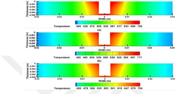
The heat generated during friction welding should be sufficient to soften, mix and move the materials. The calculated temperature profiles lengthways the upper surface of the sample and the transverse units through the tool axis figures (1.4, 1.5, and 1.6).
Figure 1.4: A temperature contours on transverse section for welding speed of a- 20 mm/min b- 40 mm/min & c- 60 mm/min. Shouldar welding = 17.5 mm, tool rotation speed = 900 rpm [70].
Figure 1.5: A temperature contours on transverse section, a- 900 rpm, b- 1050 rpm & c-1200 rpm. Welding speed = 20 mm/min and shouldar welding = 17.5 mm [70].
15
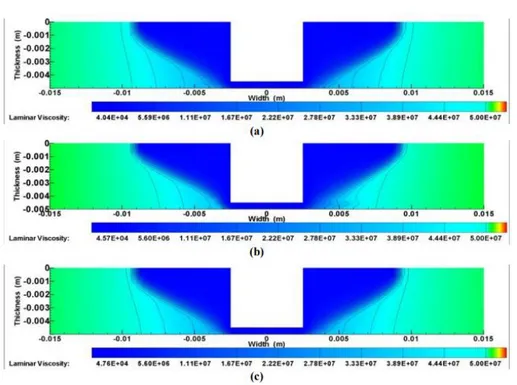
Figure 1.6: A contour schemes of viscosity at tool rotation speed of, a- 900 rpm, b- 1050 rpm & c- 1200 rpm, welding speed = 20 mm/min, shouldar welding = 17.5 mm [70].
1.7.1 Welding Speed Effect
The temperature contours of the cross section obtained during friction stir welding of (AA7075) & (AA2024) at different Tool Rotation Speed are shown in Figure (1.4). The rotation speed of the tool is maintained at 900 rpm, and the diameter of the shoulder is (17.5 mm).It can be seen from Figure (1.4), that the peak temperature decreases with increasing welding speed. As welding speed (WS) increases from (20 mm / min) to (60 mm / min), the temperature drops from (726 to 704 K). These hapules are associated with reduced heat input per unit length and heat dissipation in a wider area of the workpiece at higher welding speed (WS). When the welding speed is low, the material in front of the tool is exposed to higher temperatures. This leads to the fact that the tool is mixed, and the material softens due to an increase in temperature, reducing the forces acting on the tool. When welding speed (WS) is high, the material in front of the tool is exposed to low temperatures, as a result of which the tool mixes with relatively harder material, increasing the forces acting on the tool. This will touch the tool life [28].
16 1.7.2 The Influence of Tool Rotation Speed
The cross-sectional temperature distribution obtained during GB70 AA and AA2024 for different tool speeds (tool rotation speeds) is shown in Figure (1-5). When the tool rotation speed is (900 rpm), the peak temperature is (726 K), which increases to (739 K) and (745 K) when the tool rotation increases to (1050 and 1200 rpm), respectively. An increase in the rotation speed of the tool led to a significant increase in peak temperature due to an increase in heat production from a higher rotation speed. An increase in temperature with an increase in tool rotation speed (TRS) decreases with an increase in (TRS), since the properties of the material decrease with an increase in the temperature of the material. Thus, a constant increase in the tool rotation speed will not lead to a constant increase in the peak temperature, and therefore the maximum temperature during tool rotation speed (TRS) is approximately (80-90%) of the melting temperature of the base material [29-30].
1.7.3 Effect of Parameters on the Size of the Stir Zone
The shape of the iso-viscosity contour can well correlate with the boundaries of the mixing zone. Viscosity contours up to the order of 5x10⁶ kg-m / s correspond to the viscoplastic flow region for aluminum alloys [5]. Changes in viscosity caused by changes in tool rotation speed, weld and weld speeds at welds at cross sections are shown in figures (1- 7 & 1- 8). From figure (1- 7) it can be seen that an increase in the tool rotation speed increases the size of the mixing zone. An increase in the tool rotation speed from 900 to 1200 rpm reduces the minimum viscosity in the mixing zone with (48076.2 to 35318.2 Pa-s.). Welding and welding speed (17.5 mm) and (20 mm / min), respectively. This will consume material, mix efficiently. In addition to the above, the forces acting on the tool will be less, since the material has less resistance. A change in viscosity due to a change in the weld is shown in Figure (1.4). As the weld seam increases from (15 mm to 20 mm), the minimum viscosity in the mixing zone decreases from (43100 to 40351 Pa-s). The rotation speed of the tool and WS is 900 rpm and (20 mm / min), respectively. As the PD increases, the size of the mixing zone increases, which indicates an increase in material flow. If the weld value should be (20 mm), the size of the mixed area at the bottom of the plate also increases. The effect of HV on viscosity in the mixing zone is shown in Figure (1.8). Tool rotation speed and welding should be (900 rpm) and (17.5 mm) respectively. As the welding speed increases, the size of the mixing zone decreases, which indicates the influence of the material flow on the welding speed. It can be noted that an increase in the welding speed from (20 mm / s to 60 mm / s) at a constant tool rotation speed (1050) rpm and when welding at the seams (17.5 mm) increases the minimum viscosity in the mixing zone with (40351 , 3). Up to (47592 Pa-s). This indicates that the material will offer a
17
relatively greater resistance to tool movement, and mixing the material will not be effective at a higher welding speed [28].
Figure 1.7: A contour schemes of viscosity at shouldar welding of, a- 15 mm, b- 17.5 mm & c- 20 mm. Welding speed =20 mm/min, tool rotation speed =1050 rpm [70].
Figure 1.8: A contour schemes of viscosity at welding speed of, a- 20 mm/min, b- 40 mm/min & c- 60 mm/min. tool rotation speed =1050 rpm , shouldar welding =17.5 mm [70].
18
1.8 THE GOAL OF THE RESEARCH
The aim of this study is to study the temperature distribution of aluminum alloy (2024-T6) and to study welding parameters, such as the shape of the welding tool, the speed of rotation of the welding tool and the linear speed of the welding table. On the distribution of temperature of the alloy in the processes of friction welding (FSW).
19
2 LITERATURE REVIEW
A number of studies were conducted FSW on different types of aluminum alloys with chains (2XXX, 6XXX, 7XXXX), etc. Research and studies have focused on the properties of aluminum alloy bonding using (FSW) and its effect on properties. The internal structure of welded joints of various aluminum alloys and the type and shape of the tool used in welding. To obtain a clear conception of their study, they can be classified as follows.
[71] A. O. Al-Roubaiy, S. M. Nabat & A. D. L. Batako research of friction welding of aluminum and copper using experimental work and theoretical modeling. The (5083-H116) aluminum alloy and pure copper were successfully mixed with friction by moving the pin toward aluminum and controlling the FSW parameters. A theoretical analysis is presented along with key findings. Temperature processes are predicted analytically by the method of reverse heat exchange and correlate with experimental measurements. The temperature distribution in the immediate vicinity of the weld zone, as well as the microstructure and mechanical properties of the joint, were investigated. This was supported by finite element analysis using COMSOL Multiphysics. In this study, two rotational speeds were used and a range of displacement was applied to the pin. The microstructure of the joints was analyzed. This revealed the ingress of copper particles into the natural zone. Energy dispersive spectroscopy showed a higher rate of diffusion of aluminum to the boundary, while copper maintained a straight baseline.
[72] M. J. Jweeg; M. H. Tolephih ; M. Abdul-Sattar, finite element simulation of the distribution of transient temperatures is used to understand the physical phenomena that occur during the delay phase (excessive cleaning) and to move the welding tool during friction stir welding (FSW) of a 5 mm 7020 / T53 aluminum alloy plate at 1400 rpm and 1400 rpm and 1400 rpm min. , Thermocouples are used in places near the pin and under the shoulder surface to study in advance the excessive evaporation of the welding tool in the workpiece and to deviate the sides along the welding line in three positions (too long (start of welding), in the middle), ANSYS 12.0 numerical results are compared with experimental data , including measuring axial load at various tool speeds (710 rpm, 900 rpm, 11, 120 rpm and 1400 rpm). Based on experimental records of the transition temperature at several specific locations of the thermocouples during friction stir friction welding, the temperatures are higher on the back side (629.2 K) than on the back side (605 K) along the welding line, and the temperature at the
20
top of the workpiece under the bracket the instrument is higher (645K) than lower (635.79 K). The simulation results are in good agreement with the experimental results. The resulting peak temperature was (70%) of the melting temperature of the starting metal.
[73] Armansyah, I. P. Almanar, M. S. B. Shaari, M. S. Jaffarullah, N.Busu, M. A. F. Z. Abidin they have learned that during welding, the amount of heat present in welding zones determines the quality of welding produced. Thus, the heat distribution characteristics and their magnitude in welding zones with respect to process variables, such as pin rotation and tool rotation during welding, are analyzed using the thermal finite element analysis method. To this end, transient thermal finite elements are analyzed to simulate the distribution of temperature and its values in welding zones with respect to process variables such as rotation speed and stroke speed during welding. A commercially available program used for the Altair HyperWork program, designed to model three-dimensional tools with shoulder pins and to prepare and simulate the workplace. The results show that they very quickly check tools at expansion speeds, increasing the amount of heat produced in the weld zone. On the contrary, fast-moving speeds, at fast speeds, observe the stud tools, reducing the amount of heat produced in the welding zone.
[74] H. Bisadi; S. Rasaee; M. Farahmand In view of the increasing role of friction welding in the manufacturing industry, a full study of the process is necessary. Research, in particular at every stage of the process, provides a better understanding of friction welding and special friction welding. In this study, the degree of immersion was studied by experimental methods to study the temperature distribution around the tool during immersion and changes in the microstructure of the workpiece. The experiments were carried out on 7050 aluminum plates with the same temperature measurements. The study uses a tool with a triangle. The results of this study are used as a starting point for a theoretical analysis of the welding process. The results show that the temperature distribution around the instrument is rather asymmetric. The asymmetric temperature distribution is explained by the uneven distribution of the load under the tool and the angle of the tool. The temperature of the tool point is higher than the temperature of the tool. Microstructural studies have shown that four regions with different microstructures are formed around this instrument. These sections were divided based on differences in grain size and length. The grains next to the tool are pulled in a specific direction, indicating the direction of material flow.
[75]S. Tikader1; P. Biswas and A. B. PuriIn this article, the tool speed was kept constant, while four different types of tool geometry, two different tool speeds, and two different fracture forces were used. Thus, a series of eight experiments was carried out, and mechanical
21
properties, such as microhardness and tensile strength of welded samples, were studied for various process parameters. A mathematical model has also been developed to evaluate the heat generated in the weld zone. It was noted that friction is a major factor in heat production. It has been observed that tool rotation speed and movement speed have different effects on tensile strength and hardness of FSWed joints. An attempt is also being made to approve a theoretical model of heat production in the FSW process.
[76] X.K. Zhu, Y.J. Chao, This paper presents three-dimensional nonlinear thermal and thermomechanical numerical models for friction welding (FSW), which do not have 304 liters. Using the WELDSIM data root code, designed specifically for authors to model welding. Two cases of welding with fast technical equipment of 300 and 500 rpm are analyzed. The transition surface and residual stress in the welded friction plate of stainless steel 304 l have always been used. Based on experimental records of the transition temperature in several specific places during friction welding for 304L stainless steel, a method for the inverse analysis of thermal numerical simulation was developed. After determining the temperature field of the transition, the residual stresses in the welded plate are calculated using three-dimensional elastoplastic thermomechanical modeling. The effect of unfastening after welding on residual stresses was also studied. Comparison with the fields of residual stresses measured by the neutron diffraction method shows that the results of this numerical simulation are in good agreement with the test data.
[77] A. D. Meshram, The aim of the study is to develop a three-dimensional model of a metal sheet by friction stir welding using the finite element method for specific experimental cases, as well as to verify the data and results obtained by experimental methods. Mixed friction welding should be modeled using the FEM model using ANSYS software.
[78] A. Atak, A. Şık, V. Özdemir, This paper analyzes the friction stirring (FSSW) of magnesium sheets using the finite element method (FEM). Different types of friction welding tool (FSW) shoulders have been selected for different parameters. Thermal modeling has shown that thermal conditions vary depending on the types of tool arm construction used in friction stir welding. The thermal energy input (Q) of the numerical model was analytically solved and calculated on the basis of different parameter values. The friction coefficient pressure and the thermal properties of the materials that change when heated during friction were also taken into account in the FEM analysis. The thermal field model was numerically decoupled and the results presented.
[79] Ankit KumarSingh, Dheeraj Kumar, this study concerns the quality of the weld formed between the workpieces, determined by the amount of heat present in the welding zones (the
22
zone affected by heating) during friction welding. Thus, the characteristics of heat distribution and its magnitude in welding zones with respect to process variables such as applied force, tool and workpiece temperature, rotation speed and stroke during welding are analyzed using the thermal finite element analysis method. ANSYS 15.0 is used to model a three-dimensional pin-arm tool and to simulate the friction mixing process. The analysis is shown in this paper. [80] S. Cartiguayena; O.P. Sukeshb and K. Mahadeven, in this work, we performed numerical and experimental studies on the evolution of heat during friction with stirring (FSP) from pure copper. FSP experiments were conducted with two different combinations of processing parameters. The temperature distribution was measured using two type K thermocouples. Optical microscopes (OM) in microphotographs revealed grain detoxification, which greatly affects the heat supply during FSP. A three-dimensional (3D) non-stationary non-linear thermal model was developed using ANSYS 11.0 + software to simulate thermal history during FSP copper. The simulated temperature distributions (profile and peak temperature) were compared with experimental values. The simulation results are in good agreement with the experimental results. The results showed that heat generation during FSP strongly detonated both at rotational and transverse speeds, where it was noted that the peak temperature strongly depends on the rotation speed, while the heating rate strongly depends on the transverse speed. The resulting peak temperature was about 65% of the melting temperature of the base metal.
[81]D. H. Lammlein, in this paper, it was demonstrated that small diameter pipelines can be effectively connected using a simple FSW tool. A twisted shoulder and threaded probe tool was used to make full welds on pipes with a diameter of 4.2”and a wall of 0.2”. The welds were extremely superficial and reached a tensile strength of more than 70% of the starting material over the limited range of parameters tested. The work done here extends the use of PSV to small diameter pipes with a wide range of applications, for example, in the oil industry. [82]Basil M. Darras, in this work, commercial aluminum alloy 5052 sheet is agitated friction, machined with different rotation and rotation speeds. [The influence of process parameters on the obtained microstructure and mechanical properties is investigated. The results show that FSP creates a very fine and uniform grain structure, and it is observed that a structure with a smaller grain size is obtained at lower rotational speeds].
[83] S. K. Hussein, in this study, five types of probe (cylindrical, quasi-cone, square, hexagonal and multi-cylindrical), shoulders (cylindrical, cylindrical - flat slot, cylindrical - double flat slot, cylindrical - slot for one semicircle and cylindrical) and weapons tools are used and considered as levels of the Taguchi method. With Minitab, this method offered 25 types
23
of tool construction. The heat output from each type of tool is calculated by the finite element method using Comsol Multiphysics. The influence of each type of probe, arm, and handle of the tool on the change in heat production is analyzed. The design of the experiment method is used to optimize the maximum heat output of the proposed tool type. The maximum heat is produced in the type of tool that contains a hexagonal probe and a round slit arm. Increasing the number of slits in the shoulder leads to an increase in the heat produced. The handle of the tool, which contains the circumferential fins, gives more warmth compared to the smooth type. [84] R. Janarohan1, V. Appalaraju, in this work, static analysis is to determine the deformation, stress and strain at different speed (800,650 & 450 rpm) of the cutting tool. And thermal analysis is the definition of heat flow and temperature distribution. Two process parameters, ie round pin profile and speed. It is established that the hinge made with the use of a round screw thread has excellent tear, shock and hardness properties.
[85]R. Mohan; N. R. Rajesh and S. S. Kumar, [This paper provides a three-dimensional finite element thermal analysis of friction stir welding in Comsol Multiphysics. In the current model, only heat generation due to friction is considered. The heat profile obtained during the simulation showed good agreement with previously published experimental results. Three factors were studied, namely axial force, welding speed and speed, each of which has three different levels. The optimization of process parameters at the maximum temperature was carried out using the Taguchi method based on the Taguchi orthogonal array L9. With this approach, every answer, that is. The temperature is transferred to the appropriate signal-to-noise ratio using the larger Taguchi criterion (LBT). The optimal welding parameters obtained after analysis are F = 5000 N, S = 80 mm / min and N = 1600 rpm. Compliance checks are performed using these process parameters. The maximum temperature obtained was 590.62 ° C, which is 89.4% of the melting temperature of the material].
[86]Z. Zhu ; M. Wang; H. Zhang; X. Zhang; T. Yu and Z. Wu, [As part of this study, a three-dimensional thermomechanical model with coupled finite elements was developed for predicting and analyzing the formation of defects in friction welding based on the Euler Lagrangian method. The model is checked by comparing the calculated welding temperature, the shape of the treated section and the size of the void with the experimental results. Comparable results show that the simulated temperature and the measured data are in good agreement with each other. In addition, the model can accurately predict the shape of the plasticized zone and the presence of voids in the seam. However, the void size is overestimated].
24
[87] K. Mroczka, This article presents the welding results of AlSi9Mg cast (hypoelectric silumin) and 2017A aluminum alloys. Welding was performed at a high linear speed over 1 m / min. The modification of the method was to shift the welding line in the direction of the advancing side and to use an additional source of heat from the root. The study of the macrostructure (high resolution image) revealed the presence of defects in the weld, despite the greater plasticity of the material due to the increase in temperature.
[88]M. Al-Moussawi, in this study, the simulation of friction during welding with external computational fluid dynamics was provoked. Use the interface between tools and workpieces that used three different approaches; its torque, sticking / sliding and using sticking. The results of mathematical modeling of FSW with the use of CFD showed that the acceleration in stylistics is the most effective approach for modeling friction, which supports welding. Experimental work has also shown a significant improvement in the energy properties of welded joints from the point of view for the second time and the secrecy at break after friction welding while increasing the equation mainly with the parent metal. A new technique for estimating the peak temperature and cooling rate with TiN sediments may also be an alternative to thermocouple measurements, which can significantly lower the temperature of the workpiece interface.
[89]J. Mirmasoud, This article presents the results obtained and the calculations made as a result of analytical modeling, including friction welding with stirring Al 2024-T6. A new database has been developed to model the contact temperature between the tool and the workpiece. A second-order equation is proposed for modeling temperature at the interface and thermal history during the immersion phase. The influence of the preheating temperature on the process time was investigated using the proposed model. The results show that an increase in preheating time leads to a reduction in the time of the immersion process and the preheating stage. The results of modeling the thermal history showed consistent agreement with the corresponding experimental data from the literature.
[90] Manikandan, T. P. Pillai, this research experiment provides a temperature property in the form of an empirical model, which is formed using such a scientific computing tool as (MAT LAB). This model can be used to further predict impact properties in the experimental range.
[91] M. Z. H. Khaindkar, J. A. Khan and A. P. Reyniolds, A new three-dimensional thermal model is proposed for studying the distribution of transition temperatures in friction welding with stirring of an aluminum alloy. The results of the reference to the thermal properties of the
25
tolerances of the welding material were used for numerical simulation on the CIT element. Good agreement between the simulated temperature sensors and experimental data is shown. [92] A. K. Kadian, G. Puri , P. Biswas, in this work, the source of friction is considered the source of friction between the tool and the surface of the part, as well as the deformation of the material during shear. A comparative study between predicting a thermal history due to heat release due to friction and heat release due to friction and displacement of material deformation. The predicted numerical thermal profiles were well compared with the experimental results with a smaller error, which confirms various assumptions made in the article.
[93] R. Padmanaban, V. R. Kishore, and V. Balusamy, This article develops a numerical model based on computational fluid dynamics to predict the distribution of temperature and material flow during the ROM of various aluminum alloys AA2024 and AA7075. The fluid flow approach is used, and the FSW process is modeled as a stable visco-plastic laminar flow using a rotating cylindrical tool. The results show that the peak temperature in the welded plates increases with increasing tool rotation speed (TOOL ROTATION SPEED) and, while the peak temperature decreases with increasing. Increasing the TOOL ROTATION SPEED and shoulder diameter increases the material flow, and increasing the welding speed reduces the material flow in the mixing zone.
[94] Q. M. Doos, A. Zaidan, H. R. Hassan, This paper uses two-dimensional finite element analysis to study the thermal history and thermomechanical process of welding aluminum alloys. The model includes the mechanical reaction of the tool and the thermomechanical process of the welded material. The heat source included in the model includes friction between the material and the probe and the arm. The calculation result also shows that preheating the workpiece before the process is useful for friction stir welding.
[95] Armansyah, I. P. Almanar, M. S. B. Shaari, M. S. Jaffarullah, For this study, transient analyzes of thermal finite elements are carried out to simulate the distribution of temperature and its values in the welding zones, taking into account variable technological processes, such as rotation speed and travel speed during welding. Available for sale, Altair HyperWork software is a used 3D tool with a shoulder lock. Workpieces and simulation of the friction mixing process. The results show that an increase in the speed of rotation of the tool at a constant speed will lead to an increase in the amount of heat generated in the welding zones. On the contrary, an increase in the speed of movement at constant speeds of rotation of the studded tools will lead to a decrease in the amount of heat released in the welding zones.
26
[96] A. C. Silva1; J. D. Backer1; G. Bolmsjö1, This article provides an overview of temperature measurement methods used in friction mixing. Three methods were evaluated in this article: thermocouples embedded in the tool, thermocouples embedded in the workpiece, and the method. The results show that the tool blank thermocouple is an accurate and fast method, suitable for monitoring friction feedback with stirring.
[97] M. A. Waheed , L. O. Jayesimi , S. O. Ismail , O. U. Dairo, , [In this study, advanced heat dissipation models are developed for straight and conical shoulder geometry with different pin profiles for friction welding. Based on the results obtained, the amount of heat generated is directly proportional to the number of ribs in the profiles of the pins, so that the heat generated in the profiles increases from the triangular profile of the pin to the hexagonal profile of the pin. In addition to increasing the speed of rotation of the tool at a constant speed of welding, the heat flux increases, and with an increase in the speed of welding at a constant speed of rotation of the tool, the heat flux decreases, as well as the heat generation rate on the shoulders of the flat shoulder of the tool is greater than that of the conical / conical shoulder of the tool].
[98] M Selvaraj, This article proposes a new three-dimensional thermal model based on a slip coefficient to predict the temperature distribution during friction stir welding of 304L stainless steel. From the results it was found that the rate of increase in heat dissipation per mm of weld length and peak temperature are higher at lower rotational speeds and lower at a higher rotational speed. It was found that heat generation during friction stir welding was (80.80 %) on the shoulder, (16.10 %) on the side of the pin and (3.10 %) in the lower part of the pin. [99] Mohd Anees Siddiqui, S. A. H. Jafri, Shahnawaz Alam, The article simulates the friction stir welding method using Hyper Works. The simulation results are in very good agreement with the experimental results. It is also observed that the temperature distribution in the Friction Stir Welding process is symmetrical along the welding line.
[100] Selvamani S.T, Umanath K, and Palanikumar, in this work, a moving coordinate was introduced to simulate a three-dimensional heat transfer process, since this reduces the complexity of modeling a moving tool. This model focuses on the heat supply from the tool arm and the tool pin. The temperature distribution of the weld at different welding speeds was obtained.
[101] Rasheed Nema Abed, the finite element model was performed using assembly charges (ANSYS 12.1) to consider assigning temperature at the stage of stay, the results demonstrate a decent discrepancy between the consequences of search and hypothetical tests. The most
27
extreme temperature measured under these conditions was (0.71) of the sample dilution temperature at a maximum rotation speed (1450 rpm).
Generally, electrical motors are monitored periodically and sometimes continuously for prevention of any fault occurrences. It is known that fault may develop further effects, more likely may lead to crises such as big fire of explosion in the power devices. So, the use of monitoring system is essential to keep the power equipment under the control line. Efficient monitoring procedure may help to increase the life of the power equipment and optimize the system in whole which make great economical plus points. Motor is constructed from several windings, coils sharing the same core and core is made from iron or highly conducting material. It can be understood from this introduction that motors are formulating the core of electrical machines systems and such devices are more subjectable to unwanted circumstances such as over current, faults, cooling system problems that increase the temperature of transformers coils and leads a fire or explosion. In order to tackle such events, monitoring systems are designed. This chapter contains the studies that made to protect and monitor many applications for last eight years. Below, each research that made in favor of mentoring system or protection system is being summarized, each research is entitled by its own unique reference number and is stated as follow.
![Figure 1.2: Techniques of the friction process [21-22]](https://thumb-eu.123doks.com/thumbv2/9libnet/5474575.106008/16.892.177.721.619.1026/figure-techniques-friction-process.webp)