VOLUME 60, NUMBER 13
PHYSICAL REVIEW
LETTERS
28 MARcH 1988Eff'ect
of
Tip Profile
on
Atomic-Force Microscope Images:
A
Model
Study
Farid
F.
Abraham and InderP.
BatraIBMResearch DivisionA, lmaden Research Center, San Jose, California 95120 and
S.
CiraciDepartment
of
Physics, Bilkent University, Ankara, Turkey(Received 8Septemter 1987)
Adopting the empirical silicon interatomic potential ofStillinger and Weber, we investigate the effect ofthe tip profile on the atomic-force microscope images for a prototype system, Si(001)-(2&1),and con-clude that the tip profile has aprofound effect on the observations. We also study relaxation ofthe sur-face under the influence ofthe tip using amany-body energy minimization procedure and find that the force exerted by the tip should be less than
=10
N for the atomic-force microscope to be anondes-tructive tool.
PACSnumbers: 61.16.Di
The scanning tunneling microscope'
(STM)
and more recently the atomic-force microscope 3(AFM)
have proved to bevery successful in imaging surfaces at atom-ic resolution. On the basis of the theory of tunneling developed by Bardeen, Tersoff and Hamann showed that inSTM
the tunneling current is proportional to the local densityof
states. The result becomes particularly simple for a spherical tip with an s-type wave function. In this case, the local densityof
states need only be eval-uated at the centerof
the tip. The spherical s-wave tip model, for all practical purposes, acts as an isolated single-atom tip. Mizes, Park, and Harrison have re-cently considered the effectof
a diatomic tip onSTM
imagesof
the graphite surface and proposed an explana-tion for many anomalous images obtained for this sys-tem. The monoatomic-tip imageof
graphite is known to be the centered hexagon with 2.46-A. periodicity aris-ing from atoms(8)
having no neighbors directly below in the next lower layer.The effect of the tip shape on the AFM images is largely unknown although it is suggested that even in the
STM
mode atomic forces play a dominant role for graphite. The inclusionof
tip-surface interactions has been recently pursued, 'o ' but very little is said about the effectof
the tip profile on the AFM images. In this paper, we consider the effectof
the tip structure and shape on the AFM images by performing force and ener-gy calculations on a prototypeSi(001)-(2x
1)
surface in-teracting with an idealized AFM tip consistingof
one to four silicon atoms. We adopt the Stillinger-Weber' in-teratomic potential for calculating forces and surface re-laxations (due to the presenceof
the AFM tip) using a molecular relaxation technique. This procedure has suc-cessfully obtained the unbuckled-dimer bond formation' onSi(001)
and the atomic relaxations and formation en-ergiesof
self-interstitial defects in silicon. ' The Stil-linger-Weber potential was optimized along an isochorefor the bulk crystal and liquid, and by use
of
the molecular-dynamics simulation technique it was demon-strated that the interface between the two phases can be described accurately. ' The surface was modeled by an 8-layer-thick slab along the[001]
direction and a vacu-um space where the AFM tip was placed.To
avoid end effects, the large surface unit cell(64
atoms per layer) was periodically repeated. We examined six different typesof
tips: T~, T2, T2tt, Ts, Tstt, and T4. the numeri-cal value in the subscript gives the number ofSi
atoms constituting the particular tip.It
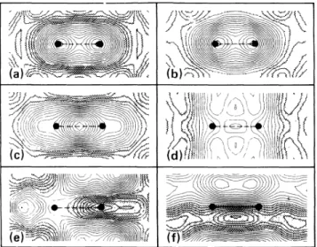
is important to realize that currently there isno feasible formalism available for AFM at any self-consistent field level for such largesys-FIG. 1. The contour plots ofthe force on various tips above
the Si(001)-(2X1)surface, without surface relaxation: (a) T~,
(h) T4, (c)T2, (d) T2n, (e) T3, (f) T3n. The shaded areas
show the attractive force regions. The surface dimer atoms are indicated by filled circles.
VOLUME 60, NUMBER 13
PHYSICAL REVIEW
LETTERS
28MARCH 1988tems. An ab initio calculation has been presented ear-lier' but was restricted to a monatomic tip only. The use
of
empirical potentials with a many-body energy minimization procedure thus represents an important ad-vancement for the explorationof
tip geometry effects and tip-induced relaxationof
the surface.We first consider the surface and the tip atoms as rig-id. We will learn later that the effect
of
tip-induced sur-face relaxation does not change the qualitative featuresof
the analysis as long as the AFM is a nondestructive probe,i.
e., when the tip is beyond=2
A and forces are in the rangeof
10 N. Figures1(a)-1(f)
give the con-tour plots for total normal forces experienced by a tip placed at a vertical distanceof
=2
A.To
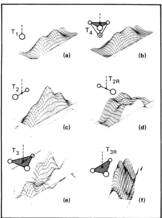
visualize the topography, the corresponding surface plots are given in Figs.2(a)-2(f).
The insets give the shapesof
all the tips. There are two typesof
diatomic tips (T2, T2g) and triatomic tips(T3
T3+).
The T2 tip had its two atoms placed parallel to the surface dimer bonds and the T2~ tip had the atoms in the same z-plane but orthogonal to the surface dimers. Interatomic distance between the two tip atoms was set at theSi
bulk bond length. The tetramer tip(T4)
had a pyramid shape, the blunt tri-angular face being farthest from the surface. The tria-tomic tips were generated by our removing the atom atthe apex. The triatomic tips were placed in two different orientations with respect tothe surface. For T3, one side
of
the triangle was parallel to the y axis, while for T3~ the side was parallel tothex
axis (the dimer bond direc-tion). A significant point to note is that, unlikeSTM
where phase factors cause major complications in the study ofthe tip shape, the AFM offers no such difficulty. In the case that relaxation is ignored, a multiatom tip image can easily be created from a single-atom tip image by linear superposition.From Figs. 1 and 2, one can draw conclusions about
the AFM images to be seen for each tip profile. As ex-pected, at the vertical distance of
=2
A, the forces are repulsive (highlighted in Fig.1);
todate no atomic reso-lution has been reported in the attractive regime.%e
mention that only tips T~ and T4 resolve the surface as consisting of dimer atoms. Tip T4 behaves much like a single-atom tip; the atoms farther from the surface do not play any significant role except for a minor distortionof
the image. Tip T2 experiences the most repulsive force when its two atoms are above the surface dimer atoms. Thus the diatomic tip shows a pronounced max-imum at the center ofthe surface dimer atoms. Tip T2 thus sees a single surface atom (actually the surface di-mer bond). The tip T2n shows a spectacular picture in that it highlights five regions in the surface cell.It
ex-periences the most repulsive force when at least oneof
the tip atoms is on topof
oneof
the surface atoms. When that happens, the center of the tip is displaced along the~
y direction from the dimer atoms, giving rise to four maxima. The fifth maximum occurs when the tip atoms bisect the surface dimer bond orthogonally. Tip atoms are equidistant from the surface atoms and this lead to a repulsive force at the tip. The tip T3shows an unusual pictureof
the unit cell [see Figs.1(e)
andI 2R (a) ,T3R I (c) (ej
FIG.2. The surface plots ofthe force on various tips above
the Si(001)-(2X 1)surface, without surface relaxation: (a) T~,
(b) T4, (c) T2, (d) T334, (e) T3, (f) T3R Height above
the.
reference line indicates magnitude ofthe repulsive force.
FIG.3. Black and white AFM images of
Si(001)-(2x
1) ex-pected from four different tips and no surface relaxation: (a)T~, (b) T3,(c)T2,and (d) T3+.
VOLUME 60, NUMBER 13
PHYSICAL REVIEW
LETTERS
28 MARcH 1988 TABLEI.
Calculated normal forces (repulsive, with positivesign) on a monoatomic tip (in units of 10 N) in the absence, Fm, and in presence, FTf, ofsurface relaxation for the tip in
on-top (A) and the mid-dimer (M)sites for several heights (h)
above the Si(001)-(2x 1)surface. Site M M M M h (A) 1.06 1.06 1.54 1.54 2.02 2.02 2.50 2.50 FTo 428.15 63.02 57.28 23.02 9.18 6.49
—
1.82—
2.40 FTf 2.92 2.03 3.50—
0.18 1.00—
0.75—
0.54—
1.432(e)].
It shows the surface dimers but at the sideof
the unit cell rather than in the middle. In addition, it images a single atom at the left-hand side ofthe unit cell. Such an AFM image would lead toall kinds offaulty interpre-tations unless the tip shape is properly taken into ac-count. This image can be readily understood if during the scan it is kept in mind that the short side of the unit cell is equal to the side ofthe tip. The image due to the tip T3R can be similarly constructed. In Fig. 3 we have created black and white AFM images for several tips. A repulsive tip force above a certain critical value is shown in white and below this critical value is shown in black. White areas thus represent maximum deflection of the cantilever in theAFM.
It
is obvious that the true imageof
the surface isobtained with a monoatomic tip.So
far our discussion has assumed a rigid surface and tip. The reconstruction of the surface's atomic topogra-phy would be significant when the tip's proximity to the surface is sufficiently close. Hence, it is important to determine under what conditions the surface definition can be maintained while accounting for surface relaxa-tion at various tip-surface separations. Our molecular relaxation calculations are uniquely suited to examine this issue. For a single-atom tip, located at various heights above A andM
sites, the initial and final (after surface has fully relaxed) calculated forces on the tip are given in TableI.
Note that when the tip height is less than=1.
5 A from the surface, the relaxation is severe and the force topography issignificantly reduced. Under these circumstances the AFM tip will alter the surface being investigated. The relaxation-induced reductionof
force is still likely to reflect surface topography only when the tip is beyond
=2
A and forces in the rangeof
10-'
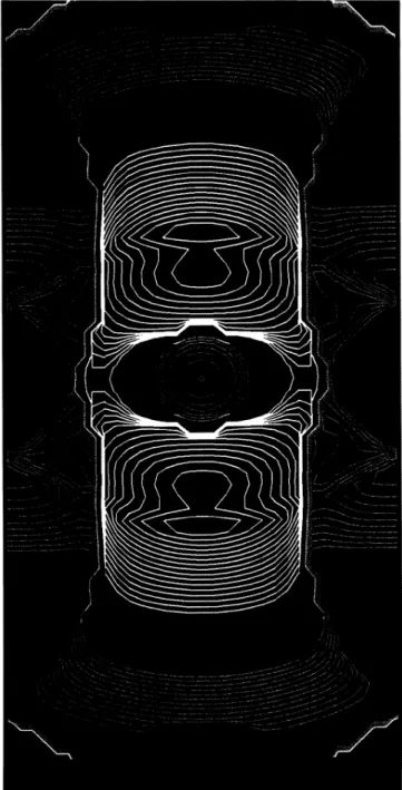
N.Figure 4 shows the contours for the force experienced by the tip after complete surface relaxation. The forces on the single-atom tip were calculated at a fine xy grid for a height
=2
A ofthe single-atom tip above the sur-face. The forces are still repulsive around the surfaceFIG.4. The contour plots ofthe force experienced by the tip
Ti (held at
=2
Aabove the surface) after the completerelax-ation ofthe surface due to the tip's presence at each surface (xy) site. Contours in white show the repulsive regime. At-tractive force in the range of0to
—
0.83is shown in turquoise, between—
0.83 and—
1.66 in yellow, between—
1.66 and—
2.49 in green, between—
2.49 and—
3.32in red, and less than—
3.32inblue. All forces arein units of 10 N.atoms but in between
(at
the dimer bond site) the force is now attractive. The attractive force indicates weaken-ing ofthe dimer bond due to the presenceof
the tip. In the absenceof
surface relaxation the forces wererepul-VOLUME 60, NUMBER 13
PHYSICAL REVIEW
LETTERS
28 MARcH 1988sive at both sites [see Table I and Fig.
1(a)j.
Thus the AFM would resolve the atoms but perhaps with some-what reduced contrast as a resultof
relaxation. Since the atomic relaxation occurs on a much shorter time scale as compared to the scan speed, the relaxation willoccur in real systems and will tend to smooth out the force corrugation. Also, it should be noted that a mul-tiatom tip image cannot be created from a single-atom tip image by a simple superposition ifsurface relaxation due to the tip's presence isallowed.
In summary, it can be stated that the tip profile can have profound eff'ect on the AFM images. Furthermore, ifthe force between the tip and the surface is too repul-sive, the surface atoms will significantly relax to lower forces and the resulting image may not be that ofthe un-disturbed surface. This has important implications for studies
of
biological materials with use of AFM which have tremendous flexibility and can readily relax. For silicon we find that the force exerted by the tip should be less=10
N for AFM tobe a nondestructive tooLG. Binnig, H. Rohrer, Ch. Gerber, and E.Weibel, Phys. Rev. Lett. 49,57(1982),and 50, 120
(1983).
2G. Binnig, C.F.Quate, and Ch. Gerber, Phys. Rev. Lett. 56, 930(1986).
3G.Binnig, Ch. Gerber, E.Stoll, T. R.Albrecht, and C.
F.
Quate, Europhys. Lett. 3,1281(1987).
J.
Tersoff and D. R. Hamann, Phys. Rev. Lett. 50, 1998(1983).
~H. A.Mizes, Sang-Il Park, and W. A.Harrison, Phys. Rev. B36,4491 (1987).
G. Binnig, H. Fuchs, Ch. Gerber, H. Rohrer, E.Stoll, and
E. Tosatti, Europhys. Lett. 1, 31 (1985);Sang-Il Park and
C. F.Quate, Appl. Phys. Lett. 4$, 112
(1986).
7J. Schneir, R. Sonnenfeld, P. K. Hansma, and
J.
Tersoff, Phys. Rev. B 34, 4979 (1986).I.
P. Batra, N. Garcia, H. Rohrer, H. Salemink, E.Stoll,and S.Ciraci, Surf. Sci. 181,126(1987).
J.
M. Soler, A. M. Baro, N. Garcia, and H. Rohrer, Phys. Rev. Lett. 57,444(1986).
' U. Duerig,
J.
K. Gimzewski, and D. W. Pohl, Phys. Rev.Lett. 57,2403 (1986).
J.
B. Pethica, to be published;J.
K. Gimzewski andR.Moiler, Phys. Rev.B 36, 1284(1987).
'
I.
P. Batra andS.
Ciraci, in Proceedings ofSecond Interna-tional Conference on Scanning Tunneling Microscopy/Spec-troscopy, Oxnard, California, July 20-24, 1987,J.
Vac. Sci. Technol. (to be published); S. Ciraci andI.
P. Batra, Phys. Rev. B 36,6194(1987).' F.H. Stillinger and T. A. Weber, Phys. Rev. B31,S262
(1985).
F.
F. Abraham and I. P. Batra, Surf. Sci. 163, L752 (1985).I.
P. Batra,F. F.
Abraham, andS.
Ciraci, Phys. Rev. B 35, 9552(1987).'SF. F.Abraham and