Embedded arrays of annular apertures with
multiband near-zero-index behavior and
demultiplexing capability at near-infrared
A
NDRIYE. S
EREBRYANNIKOV,
1,2,*H
ODJATH
AJIAN,
3M
ACIEJK
RAWCZYK,
2G
UYA. E. V
ANDENBOSCH,
1 ANDE
KMELO
ZBAY3,41ESAT-TELEMIC, Katholieke Universiteit Leuven, 3001 Leuven, Belgium 2Faculty of Physics, Adam Mickiewicz University, 61-614 Poznań, Poland
3NANOTAM - Nanotechnology Research Center, Bilkent University, 06800 Ankara, Turkey
4Department of Physics, Department of Electrical Engineering, UNAM - National Institute of Materials Science and Nanotechnology, Bilkent University, 06800 Ankara, Turkey
Abstract: In this paper, we study transmission through the embedded arrays of subwavelength
annular apertures at near-infrared. Single, i.e. non-embedded arrays of annular holes are known for their capability for high-efficiency transmission even through rather thick apertures in a wide frequency range, extending from microwaves to the visible. In the suggested structures, which contain up to four embedded arrays, multiband operation can be obtained, so that each array is mainly responsible for one of four transmission bands. In such a way, a demultiplexing-like functionality can be realized, i.e. the desired parts of the incident-wave spectrum are distributed between several transmission channels. In the studied structures, we obtain (nearly) zero phase advancement and that indicates near-zero-index behavior at the expected propagation thresholds of plasmonic modes in the frequency domain. Therefore, the earlier developed concept of supercoupling and squeezing into very narrow waveguide channels is applicable to the studied structures. The number of near-zero-index bands is determined by the number of the embedded arrays. The effects of thickness, width of the slits, and permittivity of the filling material are numerically studied and discussed in detail. It is shown that multiband transmission may exist in the near-zero-index regime in a very wide range of parameter variations.
© 2019 Optical Society of America under the terms of theOSA Open Access Publishing Agreement
1. Introduction
Two decades ago, transmission through subwavelength circular holes and slits attracted the interest of the research community [1,2]. Later, advanced aperture shapes were proposed. Among them, annular hole arrays are distinguishable because they enable stronger transmission than circular hole arrays [3,4]. Moreover, transmission occurs at wavelengths much larger than the conventional cutoffs for circular apertures. Initially, this feature has been expected to appear, since the cutoff-free TEM mode may propagate in a waveguide channel having a coaxial cross-section. However, transmission enhancement has also been observed at normal incidence, at which TEM mode cannot be excited [5,6]. Therefore, higher modes which have the cutoff nature should be the main contributors to the resulting transmission.
Both the PEC/lossy metal case [5–10] and the case of realistic Drude metals [3–5,11–14] have been examined for the arrays of annular apertures theoretically and experimentally. The obtained results cover a very wide frequency range, which extends up to the visible. The comparison of transmission in the cases of PEC approximation and a realistic metal in the visible range showed the significant difference, which occurs due to the plasmonic effects [15]. It is interesting that transmission may also be significant at a rather large array thickness, while the cutoff nature of transmission remains in case of arrays made of Drude metals.
#365710 https://doi.org/10.1364/OME.9.003169 Journal © 2019 Received 23 Apr 2019; revised 12 Jun 2019; accepted 15 Jun 2019; published 27 Jun 2019
In Ref. [5], the behavior observed in the annular hole arrays, i.e., super-enhanced transmission, has been attributed to the cavity resonance of a single guided mode. In Refs. [11,15], it has been attributed to the effects exerted by cylindrical surface plasmons (CSPs) at the aperture walls. They can be considered as a particular case of the localized surface plasmons [16–20]. In addition to the periodic arrays of annular holes, like the ones in [3–6,11,15], single annular apertures have been studied in the lossy metal case at microwave frequencies [21], and in the framework of the Drude model at the near-infrared [15] and the visible [12]. The effects of transmission through the annular apertures can be combined with the effects exerted by (spoof) surface plasmons, which appear due to the coaxial corrugations surrounding a single annular aperture, in order to obtain directive beaming [10,22].
The previous works should be mentioned, which present the results of parametric studies of annular apertures. For example, the effects of variation of the aperture-diameter-to-array-period ratio have been theoretically studied in the PEC case [8]. The effect of array period has been experimentally studied in [13] at the near-infrared. The effects of the inner radius of aperture and array thickness have been considered in case of a single annular hole for the visible frequency range [15]. Plane-wave illumination has been mainly utilized in the above-mentioned works. On the contrary, beam illumination has been considered in [10,12,22,23]. This has been done for a periodic array in the PEC slab [23], a single hole in the PEC slab with corrugations [10,22], and a single annular hole in a noncorrugated metal slab at the visible [12]. Systematic reviews of the performances, physical scenarios, and achievable operation regimes for the structures with subwavelength holes, including the annular ones, can be found, for instance, in Refs. [24,25].
While the aspect of enhanced transmission through subwavelength apertures has been dominant in the early studies of the annular hole arrays, some new applications have been suggested later. For example, structures with enhanced magneto-optical activity [26] and surface acoustic wave applications [27] should be mentioned as well as magnetic mirrors [28]. In the last case, periodic arrays with unit cells comprising two embedded apertures of different radii have been used. The common effect of two different Fabry-Perot resonances in the apertures of larger and smaller radius at the same frequency has been exploited in [28] to obtain the magnetic mirror functionality in the PEC approximation and for a realistic metal at the near-infrared and visible frequencies. Reference [28] is probably one of a few works, in which the embedded arrays have been studied. Some aspects of coupling in similar arrays with two apertures per unit cell have been considered in [29]. A model of coupling in periodic arrays with several elements per unit cell, which is based on the circuit model, has been suggested in [30] without the concretization of shape. An example of the use of two embedded apertures (no array) in the plasmonic lens is given in [31]. Another important class of applications, in which annular hole arrays could be used widely, includes demultiplexing [32] and separation [33] of optical signals.
In this paper, we numerically study transmission through the periodic arrays of the embedded annular apertures in a Drude metal slab, with four apertures per unit cell, for the near-infrared frequency range. The focus here is the assessment of two hypotheses. The first one is whether multiple plasmonic modes yielding multiple transmission bands can be obtained in the subwavelength range by increasing the number of the embedded apertures. The second one is whether the bands of high transmission can be attributed to the near-zero-index (NZI) regime, and whether such multiple bands may occur in NZI regime, while staying in the subwavelength range. To assess, an extensive parametric study is performed by varying the array thickness, width and number of apertures, and permittivity of material that fills the apertures. Indeed, since the properties of plasmonic modes are expected to depend on aperture radius, the use of several embedded apertures within each unit cell might lead to multiple modes within a relatively narrow frequency range.
It is known that filling apertures with an epsilon-near-zero (ENZ) material enables supercoupling and squeezing into very narrow channels [34,35]. Moreover, behavior equivalent to the one with a
near-zero index of refraction can be obtained at the cutoff of a waveguide mode in the wavelength domain [36,37] and for the specially designed photonic crystals [38]. At the same time, the results obtained earlier for annular apertures may indicate the cutoff nature of the plasmonic modes that mainly contribute to the resulting transmission in the near-infrared range at normal incidence [11]. It will be demonstrated that the number of transmission bands in the subwavelength range is really determined by the number of the embedded apertures. Therefore, each aperture is mainly responsible for transmission within a particular frequency range what yields capability in multiplexing. It will be shown that four first (lowest) transmission bands can be connected with the NZI regime, provided that the array thickness is properly chosen. Nonzero-order Fabry-Perot resonances may be responsible for higher transmission bands in the same structure. The hybrid transmission mechanism will also be discussed, in which different apertures of the same unit cell work in either NZI regime or nonzero-order Fabry-Perot regime. A weak effect of thickness on the spectral location of a transmission maximum is one of consequences of NZI behavior. To compare, we provide the results for a terahertz analog of the studied near-infrared structures. The results presented in this paper are obtained by using CST Microwave Studio, a commercial software based on the finite integration method [39].
2. General geometry
The studied structures represent periodic arrays of annular holes, with one to four embedded holes per each unit cell. The geometry is shown in Fig.1for the most general, i.e., four-aperture case. The material of the studied arrays is assumed to be silver. Its relative permittivity is given at the near-infrared by Drude model, i.e.
ε = 1 − ω2
p/[ω(ωp+ iγ)], (1)
where ωp = 1.37 × 10¹⁶s−1is plasma frequency and γ= 2.73 × 10¹³s−1is collision frequency.
For comparison, we also consider transmission through one array at terahertz frequencies. In this case, silver is assumed to be a lossy metal with conductivity σ= 6.3 × 10⁷S/m.
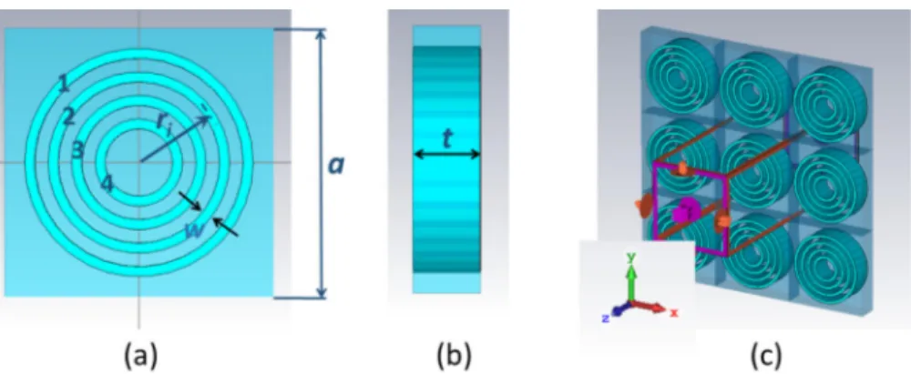
Fig. 1. General geometry of the studied structure: (a) unit cell of two-dimensional periodic structure obtained by embedding four arrays of annular apertures with mid-radius ri, i= 1, 2, 3, 4, front view; (b) cross-section of the same unit cell; (c) fragment of the studied structure being infinite in (x,y)-plane, which contains 3 × 3 unit cells, perspective view.
The following array nomenclature is used throughout the paper. The notation 1234 stands for the basic structure having four concentric annular slits per unit cell, as shown in Fig.1(a); 1, 2, 3, and 4 stand, respectively, for array in which only 1st, only 2nd, only 3rd, and only 4th slit is kept unfilled, while three remaining slits are filled by metal. Then, 13 stands for the array with two unfilled slits per unit cell: the 1st and 3rd ones. Finally, 12 denotes the array in which
only the 1st and 2nd slits are kept unfilled. In case of wide slits, we take w= 30 nm. In case of narrow slits, w= 10 nm. The mid-radii of the 1st, 2nd, 3rd, and 4th slits are chosen as 325 nm, 255 nm, 185 nm, and 115 nm, respectively. Thickness and period of the array are denoted by
tand a, respectively. εs denotes the relative permittivity of a material filling the slits. The
spectral properties of CSPs in the slits are expected to be sensitive to the variations in εs, as
happens for the conventional surface plasmons at a flat metal-dielectric interface, i.e., resonance frequency may be downshifted while εsis increased. Consideration is restricted here to the case
of a normally incident, linearly polarized plane wave.
3. Results and discussion
3.1. Basic effects in transmission
Figure2(a) shows the transmission (T = |S21|) for the arrays with one, two, and four annular
apertures per period, in case of narrow slits (w = 10 nm) and a relatively large thickness (t = 200 nm). For the structure 1234, we observe four transmission bands, which are well separated from each other. Assuming that the waveguide properties of the annular channels depend on the aperture radius, one may expect that each of four bands appears due to one of the four apertures, i.e., one of four transmission channels, for each unit cell of the array. To clarify this point, we compare the results for the structures 1234, 1, 2, 3, and 4 in Fig.2(a). It is observed that (i) the number of bands is equal to the number of apertures, and (ii) spectral locations of the maxima of T for the structure 1234 approximately coincide with the ones for the structures 1, 2, 3, and 4. Therefore, the features observed in Fig.2(a) argue in favor of our expectation.
Fig. 2. (a) Transmission for arrays 1234 (solid dark-blue line), 1 (dashed red line), 2 (dash-dotted green line), 3 (dotted black line), 4 (dotted blue line). (b) Transmission for arrays 1234 (solid dark-blue line), 12 (dash-dotted green line), and 13 (dashed red line); a= 800 nm, t = 200 nm, εs= 1; narrow slits.
The maxima of T for the structure 1234 are located at f = 65, 85.5, 119, and 189 THz, what corresponds to a/λ= 1/5.75, 1/4.37, 1/3.14, and 1/2, respectively. Noticeably, t/λ = 1/23 and w/λ= 1/460 for the first (lowest) maximum, t/λ = 1/8 and w/λ = 1/160 for the fourth maximum. Transmission at the maxima is rather strong for all of the structures in Fig.2(a). In particular, T= −2 dB, −2.4 dB, −3.2 dB, and −3 dB, respectively, for the maxima of T in the structures 1, 2, 3, and 4. It is interesting that for the first and the second maximum, T in the structures 1 and 2 is higher than in the structure 1234. On the contrary, T at the third and the fourth maximum is lower in the structures 3 and 4 than in the structure 1234. The maxima in the structure 1234 are spectrally shifted, as compared to the structures 1, 2, 3, and 4. The shift is strongest for the 1st and 4th bands.
In Fig.2(b), we compare transmission for the structure 1234 and the structures having two apertures per unit cell, i.e., 12 and 13. The results shown in Fig.2(b) give one more confirmation that each aperture is mainly responsible for one of the bands. It is seen that two maxima appear
for each of the structures 12 and 13 nearly at the same frequencies as some of the maxima for the structure 1234. Therefore, when the incident wave has several spectral components, they will be distributed between the different transmission channels, each being created by one of the embedded arrays, i.e., demultiplexed. If the incident wave comprises spectral components in the vicinity of f = 72.5, 105, and 177 THz, it will be nearly perfectly reflected from the structure 1234. The shifts of the maxima of T observed in Figs.2(a) and2(b) can be attributed to the
coupling between the apertures of either the neighboring unit cells or the same unit cell. Next, let us consider the case of wide apertures, w= 30 nm. The results are shown in Fig.3, for the structures having all the same geometrical parameters as in Fig.2, except for the value of w. One of the observed effects of the aperture widening is a shift of the frequencies of the maxima toward larger values. In particular, the maxima for the structure 1234 are located now at
f = 91, 122, and 172 THz, what corresponds to a/λ = 1/4.1, 1/3.06, and 1/2.17, respectively.
The second effect of the widening is a stronger difference in spectral locations of the maxima for the basic structure 1234 and the structures used for comparison, i.e., 1, 2, 3, 4, 12, and 13. Finally, the third effect is increase of T at the maxima. Now, T= −2.25 dB, −1.1 dB, and −0.75 dB at the first, second, and third maximum. Even higher T can be obtained at the maxima for the structures with a smaller number of apertures per unit cell. For instance, T= −0.6 dB for the structure 1, and −0.35 dB at the second maximum for the structure 12.
Fig. 3. (a) Transmission for arrays 1234 (solid dark-blue line), 1 (dashed red line), 2 (dash-dotted green line), 3 (dotted black line), 4 (dotted blue line). (b) Transmission for arrays 1234 (solid dark-blue line), 12 (dash-dotted green line), and 13 (dashed red line); a= 800 nm, t = 200 nm, εs= 1; wide slits.
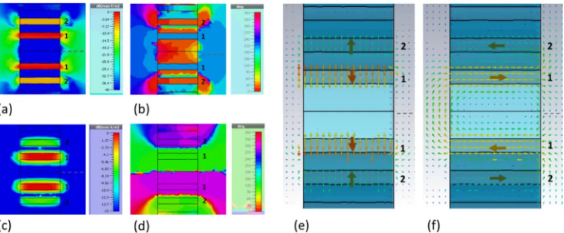
To check the guess regarding the dominant contribution of each slit to one of the high-T maxima, we plotted in Fig.4the electric and magnetic field distributions for the structure 1234 from Fig.3. One can see that the electric field is strongly enhanced inside the 1st, 2nd, and 3rd slit in Figs.4(a),4(b), and4(c), respectively. The neighboring slits may also affect the resulting transmission, as well as coupling between the slits of the neighboring unit cells. The results for the magnetic field presented in Fig.4(d-f) also confirm the guess about the dominant role of one of the slits. Taking into account the previous results for the non-embedded annular aperture arrays, it may be expected that transmission can be strongly sensitive to the choice of the aperture radii also in the case of the embedded arrays. Therefore, the features observed in Figs.2–4should not be surprising. Regardless of whether the CSP concept or the impedance-wall waveguide concept is better suitable to explain the observed transmission features, the effect of the aperture radii in the embedded arrays can be significant. As shown in Fig.4(a-f), the magnitude remains nearly the same from the input to the output side of the slit, which is the necessary condition and, thus, a signature of a nearly zero phase advancement and NZI behavior. Note that both electric and magnetic fields remain quite strong outside but in close vicinity of the array, while in- and out-coupling is strong.
Fig. 4. Magnitude of electric (a-c) and magnetic (d-f) field within two neighboring unit cells of the structure 1234 for the 1st (a,d), 2nd (b,e), and 3rd (c,f) transmission maxima in Fig.3; cross section view at the middle of unit cell, (a-c) x= 0 and (d-f) y = 0; a = 800 nm, t= 200 nm; wide slits. Incidence is assumed from the left side.
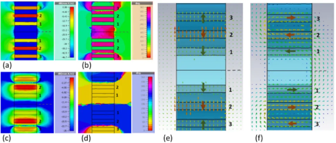
Let us further analyze a possible role of the NZI regime in transmission. Similarly to the previous works on annular apertures, assuming the cut-off type behavior of propagation inside the slits, we may expect the existence of a NZI regime within a certain frequency range. The first example is presented in Fig.5(a-d) for the first maximum of T, for which we obtained the dominant contribution of the 1st slit, as observed in Fig.4(a,d). Examination of the phase distribution clearly indicates that there is no significant phase advancement along the slits which provide the main and auxiliary contribution to the resulting transmission, at all of the maxima of T observed for the array 1234 in Fig.3. The observed phase and magnitude features clearly indicate NZI behavior at propagation through the annular channels in the high transmission regime. Moreover, according to the results shown in Fig.5(e,f), the electric field has the dominant component in the direction perpendicular to the slit walls. In turn, a magnetic field has the dominant components parallel to the walls. These two features are in good coincidence with the ones associated with supercoupling and incident-wave energy squeezing into subwavelength channels in the structures with ENZ components [34,35].
Fig. 5. Details of (a) magnitude and (b) phase for Eycomponent, and (c) magnitude and (d) phase for Hzcomponent; quiver maps for (e) electric and (f) magnetic fields, obtained by taking into account all, i.e., x, y, and z components; large arrows schematically show the dominant directions of the field vectors in the slits; cross section view at the middle of unit cells, (a,b,e) x= 0 and (c,d,f) y = 0. Numbers 1 and 2 indicate here aperture number. The gray dashed lines indicate the boundary between two neighboring unit cells. Results are shown for the first transmission maximum of the array 1234 in Fig.3, see also Fig.4(a,d). Incidence is assumed from the left side.
The second example is presented in Fig.6for the second maximum of T in the same structure as in Fig.5[also see Fig.4(b,e)]. All observed features of phase, magnitude, and field vector directions are the same as in Fig.5, except for the main contribution of the 2nd slit. This remains true also for the 3rd maximum of T [see Fig.4(c,f)], for which a figure similar to Figs.5and6is not shown. The field features observed in Figs.4–6are very general and can be obtained in a wide range of variation of geometrical parameters.
Fig. 6. Same as Fig.5but for the second transmission maximum of the array 1234 in Fig.3, see also Fig.4(b,e).
In line with the obtained results (both shown in Figs. 5, 6and not shown), transmission channels being the neighbors of the channel, which mainly contributes to the transmission, may have opposite phases, while (nearly) zero phase advancement is kept. For the electric field, all unit cells are in phase, while for the magnetic field phase in any two neighboring unit cells differs by π.
The phase behavior has also been checked for the two structures with the wide slits at
t= 200 nm and εs= 5.8, and with the wide slits at t = 600 nm and εs = 1 (not shown). In the
latter case, we found that there is nearly zero phase advancement for the two first maxima of T (at f = 92.3 and 121 THz), which appear due to the main contribution of the 1st and the 2nd slit, respectively. For the third maximum of T (at f = 166.7 THz), nearly zero advancement occurs for the main contributing channel (here, the 3rd slit), whereas signatures of the first-order Fabry-Perot resonance are observed in the channels playing the auxiliary role in transmission (here, the 1st and the 2nd slit). Hence, NZI and Fabry-Perot mechanisms may coexist in the same transmission band. For the fourth and higher maxima, field distribution in all slits contributing to the transmission is associated with nonzero-order Fabry-Perot resonances. Hence, strong transmission associated with the contribution of NZI and Fabry-Perot regimes may exist in the different transmission bands of the same subwavelength array. Operation at a cutoff that itself creates NZI behavior and filling apertures with ENZ or NZI material are probably the only physical causes of near-zero phase advancement. Since there is no filling in the slits and no transmission at small f , the observed phase advancement, which is connected with NZI behavior, may be attributed to the cutoff behavior of the plasmonic modes. Therefore, in contrast to [40], we do not arrive at the conclusion that plasmonic effects dominate the ones related to cutoff behavior.
3.2. Comparison with the THz range
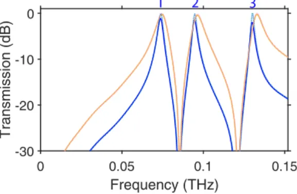
In order to demonstrate the difference between near-infrared and THz ranges, Fig.7shows T vs.
geometrical parameters from Figs.2and3are increased proportionally by factor of 1000. One can see from the comparison of Fig.7with Figs.2and3that the spectral locations of the maxima are changed not in inverse proportion to the increase of geometrical parameters. Now, we have
a/λ = 1/2.55 for the first, 1/1.98 for the second, and 1/1.44 for the third maximum. Therefore,
the values of a/λ in near-infrared regime strongly differ from those in THz regime and from the PEC case. This indicates the role of plasmonic effects at the aperture walls in Figs.2–6. These effects determine the properties of the waves propagating in the coaxial channels, and at the array interfaces, which may affect the in- and out-coupling conditions. The observed features may indicate a strong difference between the near-infrared and THz ranges in coupling conditions and modal characteristics. Obviously, the observed behavior of T can be attributed to the effect of coaxial waveguide modes [10], whose properties are free of influence of plasmonic effects. Therefore, a comparison of Fig.7with Figs.2and3clearly indicates the possible role of CSPs and other plasmonic effects.
Fig. 7. Transmission for array 1234 with a= 800 µm, εs= 1, t = 200 µm, case of wide (orange lines) and narrow (blue lines) slits; array is made of silver (solid lines) and PEC (dotted lines); dotted and solid lines are almost indistinguishable, except for the close vicinity of the maxima.
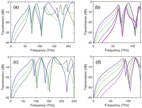
3.3. Varying array thickness
Now, let us investigate how transmission may be changed when array thickness is smaller than in Figs.2–7. Figure8shows the results for the structures 1234, 1, 2, 3, 4, with the narrow apertures, like in Fig.2, and with the wide apertures, like in Fig.3, but at t= 50 nm. A smaller thickness can be preferable, for example, because of nanofabrication restrictions. Comparison of Fig.8with Figs.2and3demonstrates the effect of array thickness on spectral locations of the T-maxima. In case of the narrow apertures in Fig.8(a), they are located at f = 63.5, 89, 130, and 214 THz, with
T= −3.15 dB, −1.6 dB, −0.9 dB, and −0.6 dB, respectively. Hence, the first maximum is located
very close to that in Fig.2, but the difference increases with the order of the maximum. In case of the wide apertures in Fig.8(b), the first, second, and third maxima are located at f= 84, 117, 171 THz, and T = −1.9 dB, −1 dB, and −0.5 dB, respectively. The smallest difference compared with Fig.3is observed here for the third maximum, and it is increased while decreasing the order of the maximum. What is new compared to Figs.2and3is that the maxima for the structures with one and two apertures per unit cell can be located now between two neighboring maxima of the structure 1234. Thus, the effects of aperture coupling should be stronger in this case. The highest transmission is achieved when w is large and, simultaneously, t is small.
Figure9shows the selected results for the structure 1234, with either the narrow or the wide slits, for several values of t between 50 and 600 nm. First of all, one can observe a relatively weak effect of t on the spectral location of the 1st and 2nd maxima. Behavior of T in the vicinity of the third and higher maxima is more complicated. The first maximum in Fig.9(a,b) can be upshifted
0 50 100 150 200 250 Frequency (THz) -40 -30 -20 -10 0 Transmission (dB)
(a)
1 2 3 4 0 50 100 150 200 250 Frequency (THz) -40 -30 -20 -10 0 Transmission (dB)(b)
1 2 3Fig. 8. Transmission for arrays 1234 (solid dark-blue line), 1 (dashed red line), 2 (dash-dotted green line), 3 ((dash-dotted black line), 4 ((dash-dotted blue line); a= 800 nm, t = 50 nm, εs= 1; (a) narrow and (b) wide slits.
by ∆f = 10 THz, as compared to the case of t = 50 nm, whereas its spectral location is the same (f = 63.8 THz) at t = 50 nm (T = −3 dB) and t = 600 nm (T = −7.3 dB). The frequency of the second maximum in Fig.9(a,b) monotonously decreases from 89.5 THz (T= −1.6 dB) to 83 THz (T= −5.8 dB), while varying t from 50 nm to 600 nm. A stronger effect of the same variation in
tis observed for the first maximum in Fig.9(c,d). Its spectral location varies gradually from 84 THz (T= −1.9 dB) at t = 50 nm to 92.3 THz at t = 600 nm (T = −3.6 dB). Finally, the second maximum in Fig.9(c,d) is nonmonotonously upshifted from 117 THz (T = −0.9 dB) at t = 50 nm to 121 THz (T= −2.1 dB) at t = 600 nm. Therefore, high transmission can be obtained also at a relatively large thickness, e.g., t/λ= 1/2.3 at t = 600 nm and f = 121 THz.
Fig. 9. Transmission for array 1234 with a= 800 nm, εs= 1; (ad) solid darkblue line -t= 50 nm, (b,d) dashed red line - t = 100 nm, (a-d) dash-dotted green line - t = 200 nm, (a-d) dotted black line - t= 400 nm, (b,d) solid violet line - t = 600 nm; (a,b) narrow slits and (c,d) wide slits.
The maxima of T, whose location weakly depends on t, for instance, the first and second maxima in Fig.9(a), are associated with NZI behavior in the whole range of t variation. Indeed, there is just a weak spectral shift of each maximum, while t is varied from 50 nm to 600 nm. This feature is inconsistent with nonzero-oder Fabry-Perot resonances. Sometimes, it is attributed to zero-order Fabry-Perot resonances. However, in our view, this is rather a mimicking of the zero-order Fabry-Perot resonance which may appear at f = 0, since it is observed here at f , 0. There are higher-order maxima of T, whose spectral location depends on t. They are attributed to nonzero-order Fabry-Perot resonances. Discussion of the possible benefits of the co-existence of NZI and Fabry-Perot transmission bands is, however, beyond the scope of this work. Finally, it is worth noting that the transmission features observed in Figs.2,3,8, and9remain in a wide range of variation of array period, a, i.e., from 700 nm to 1200 nm.
3.4. Effect of filling medium
Up to now, consideration has been restricted to the case of vacuum inside the slits. Figure10
shows the effect of filling the slits with a material with εs, 1. The structure 1234 with narrow slits is considered, like the one in Fig.2. First, it is assumed that the filling material is loss-free and has εs ≥ 1, see Fig.10(a). The increase of εsstarting from 1 leads to that the all four maxima
of the basic structure with εs= 1 are downshifted. At the same time, transmission is weakening
due to stronger reflections, which means that in- and out- coupling become weaker. For instance, the first maximum with T= −12.6 dB for εs= 5.8 is located at f = 28 THz, so that a/λ = 1/13.3.
A material with εs= 2.1 may suggest a reasonable compromise between efficiency and electrical
size. In this case, the first maximum with T= −7.2 dB is located at f = 46 THz (a/λ = 1/8.1). Similarly to Figs.2and8(a), all four lower-order resonances show NZI behavior. It is noteworthy that there is nearly the same spectral location and rather close values of T for the first maximum at εs= 1 and the second maximum at εs= 2.1, as well as for the second maximum at εs = 1 and
the third maximum at εs= 2.1. More cases of such an accidental coincidence can be mentioned.
As is known, preserving and spectrally shifting resonances in open resonance structures can be considered in terms of scaling of resonances, provided that geometrical parameters are fixed. It can be achieved by changing material parameters of some of the structural components. In [41,42], examples of such a resonance scaling and its quantification are presented for open resonance structures enabling subwavelength resonances. Assuming the general form of the scaling rule for resonance frequencies as fr(ε) = Aε−α, and choosing A= f0r = fr(1), we can
write
fr/f0r= ε−α, (2)
where ε= εsfor the purposes of this study. In the classical scaling rule, which is applicable, for
instance, to microwave cavities, we have α= 0.5 [43]. Using the results presented in Fig.10for the first and the second resonance (maximum of T), and similar but not shown results for other values of εs, we obtained that α is varied nearly from 0.25 to 0.45, depending on the considered
subrange of εs. At εs>1, Eq. (2) with α = 0.45 provides quite a good fitting of the obtained
numerical data. At εs<1, smaller values of α are required. It is interesting that the data fitting
gives very close results for α at the first and the second resonance, which appear due to the effects exerted by the different slits. To compare, α= 0.39 and α = 0.44 were obtained in [41] for the structures based on two coupled arrays of subwavelength resonators that yield chirality and polarization conversion. In Ref. [42], the values of α varied from 0.22 to 0.4 have been obtained for the arrays of H-shaped resonators which are made of a magnetically tunable material.
Combining two or more functions in the structures supporting surface plasmons is known as a route to advanced functionality, e.g., see [22,44,45]. On the other hand, the collaborative contribution of two different mechanisms to one functionality is possible. From this perspective, the common effect of the cutoff related NZI mechanism [36,37] and the mechanisms based on the use of an ENZ material [34,46,47] may be expected to collaborate in transmission enhancement
Fig. 10. Transmission for array 1234 with a= 800 nm, t = 200 nm; (a,b) solid dark-blue line - εs = 1; (a) dash-dotted green line - εs = 2.1 and dotted violet line - εs = 5.8; (b) dashed green line - εs= 0.01 and dash-dotted red line - εs= 0.2; case of narrow slits.
for subwavelength apertures. Therefore, we also consider the case when the apertures are filled with an ENZ material. Transmission has been studied for the two ENZ materials with εs= 0.2
and εs = 0.01. Although natural materials with ENZ behavior are necessarily dispersive and
lossy, we use here the loss-free and dispersion-free model, for reasons of comparison convenience. The results presented in Fig.10(b) show that the resonance frequencies are upshifted when a material with 0<εs<1 is placed inside the slits instead of the vacuum. For εs = 0.2, the first
maximum is located at f = 120 THz (a/λ = 1/3.1, T = −1.5 dB). For εs= 0.01, it is located at f = 181 THz (a/λ = 1/2.06, T = −0.6 dB). Indeed, for εs= 0.2 and εs= 0.01, T is larger at the
maxima than for εs= 1 and εs= 2.1 in the same frequency range, i.e., starting from f = 120
THz. However, transmission at εs= 0.2 and εs= 0.01 remains relatively weak in the frequency
range corresponding to the first and the second maximum of T for εs= 1 and εs = 2.1, i.e., below f = 100 THz.
4. Conclusion
To summarize, the basic effects arising in transmission through the plasmonic structures that represent the embedded arrays of subwavelength annular apertures have been studied at the near-infrared frequencies. The obtained results give evidence of the possibility of multiband operation in the subwavelength regime due to the embedding. Since the wave properties in the annular channels depend on the inner and outer radii of apertures, one can obtain strong frequency selectivity and, thus, multiband filtering in the transmission regime. Although the coupling
between the neighboring slits may come to the play, each of the arrays to be embedded (i.e., with one aperture per unit cell) provides the main contribution to one of the transmission bands of the array with several embedded apertures per unit cell. Therefore, selection and separation of certain parts of the incident-wave spectrum is achieved due to multiple plasmonic modes. This property of the embedded arrays can make them promising for demultiplexing applications, provided that a properly designed exit unit is available.
Near-zero phase advancement at the transmission maxima is an important feature, with which capability in high transmission is associated. That leads to the array’s thickness variations resulting in a weak spectral shift of the maxima that are associated with NZI behavior. Combining several apertures within one unit cell allows us to obtain multiple bands with NZI behavior. In thicker structures, NZI and nonzero-order Fabry-Perot transmission bands may coexist in the subwavelength regime. The presented results show that high transmission can be obtained for wide ranges of variation in array thickness and slit width. Filling the slits by a material with εs>1 or 0<εs<1 leads to a shift the transmission maxima of the original, i.e., non-filled
structure. For rather large εs(e.g., for εs= 5.8), coupling efficiency worsens, which results in
lowering transmission. Therefore, it is worth revisiting the coupling and squeezing scenarios in the vicinities of the expected frequency-domain propagation thresholds, by taking into account the properties of the material filling the annular channels at different radii. This topic will be the subject of a forthcoming study, as well as the potential of the embedded arrays in polarization manipulation. Recent advances in the studies conducted on tunable ENZ and NZI behavior (e.g., see [48,49]) are also promising for the near-infrared structures supporting CSPs.
Funding
Narodowe Centrum Nauki (NCN) (DEC-2015/17/B/ST3/00118 - Metasel); EU Horizon-2020 via Marie Sklodowska-Curie IF program (708200 - Advanta).
Acknowledgment
E.O. acknowledges partial support from the Turkish Academy of Sciences.
References
1. T. W. Ebbesen, H. J. Lezec, H. F. Ghaemi, T. Thio, and P. A. Wolff, “Extraordinary optical transmission through sub-wavelength hole arrays,”Nature391(6668), 667–669 (1998).
2. J. A. Porto, F. J. Garcia-Vidal, and J. B. Pendry, “Transmission resonances on metallic gratings with very narrow slits,”Phys. Rev. Lett.83(14), 2845–2848 (1999).
3. F. I. Baida and D. Van Labeke, “Light transmission by subwavelength annular aperture array in metallic films,”Opt. Commun.209(1-3), 17–22 (2002).
4. F. I. Baida and D. Van Labeke, “Three-dimensional structures for enhanced transmission through a metallic film: Annular aperture arrays,”Phys. Rev. B67(15), 155314 (2003).
5. F. I. Baida, D. Van Labeke, G. Granet, A. Moreau, and A. Belkhir, “Origin of super-enhanced light transmission through a 2-D metallic annular aperture array: a study of photonic bands,”Appl. Phys. B79(1), 1–8 (2004). 6. F. I. Baida, “Enhanced transmission through subwavelength metallic coaxial apertures by excitation of the TEM
mode,”Appl. Phys. B89(2-3), 145–149 (2007).
7. A. Roberts and R. C. McPhedran, “Bandpass grids with annular apertures,”IEEE Trans. Antennas Propag.36(5), 607–611 (1988).
8. S. M. Orbons and A. Roberts, “Resonance and extraordinary transmission in annular aperture arrays,”Opt. Express
14(26), 12623–12628 (2006).
9. P. Rodriguez-Ulibarri, M. Navarro-Cia, R. Rodriguez-Berral, F. Mesa, F. Medina, and M. Beruete, “Annular apertures in metallic screens as extraordinary transmission and frequency selective surface structures,”IEEE Trans. Microwave Theory Tech.65(12), 4933–4946 (2017).
10. H. Caglayan, I. Bulu, and E. Ozbay, “Extraordinary grating-coupled microwave transmission through a subwavelength annular aperture,”Opt. Express13(5), 1666–1671 (2005).
11. M. I. Haftel, C. Schlockermann, and G. Blumberg, “Enhanced transmission with coaxial nanoapertures: Role of cylindrical surface plasmons,”Phys. Rev. B74(23), 235405 (2006).
12. T.-D. Cheng, D.-Z. Lin, J.-T. Yeh, J.-M. Liu, C.-S. Yeh, and C.-K. Lee, “Propagation characteristics of silver and tungsten subwavelength annular aperture generated sub-micron non-diffraction beams,”Opt. Express17(7), 5330–5339 (2009).
13. M. J. Kofke, D. H. Waldeck, Z. Fakhraai, S. Ip, and G. C. Walker, “The effect of periodicity on the extraordinary optical transmission of annular aperture arrays,”Appl. Phys. Lett.94(2), 023104 (2009).
14. Y. Poujet, J. Salvi, and F. I. Baida, “90% Extraordinary optical transmission in the visible range through annular aperture metallic arrays,”Opt. Lett.32(20), 2942–2944 (2007).
15. B. Heshmat, D. Li, T. E. Darcie, and R. Gordon, “Tuning plasmonic resonances of an annular aperture in metal plate,”
Opt. Express19(7), 5912–5923 (2011).
16. J. Parsons, E. Hendry, J. R. Sambles, and W. L. Barnes, “Localized surface-plasmon resonances and negative refractive index in nanostructured electromagnetic metamaterials,”Phys. Rev. B80(24), 245117 (2009).
17. E. Hutter and J. H. Fendler, “Exploitation of localized surface plasmon resonances,”Adv. Mater.16(19), 1685–1706 (2004).
18. A. E. Serebryannikov, K. B. Alici, E. Ozbay, and A. Lakhtakia, “Thermally sensitive scattering of terahertz waves by coated cylinders for tunable invisibility and masking,”Opt. Express26(1), 1–14 (2018).
19. S. Zhou, X. Pi, Z. Ni, Y. Ding, Y. Jiang, C. Jin, C. Delerue, D. Yang, and T. Nozaki, “Comparative study on the localized surface plasmon resonance of boron- and phosphorus-doped silicon nanocrystals,”ACS Nano9(1), 378–386 (2015).
20. K. M. Mayer and J. H. Hafner, “Localized surface plasmon resonance sensors,”Chem. Rev.111(6), 3828–3857 (2011).
21. M. J. Lockyear, A. P. Hibbins, J. R. Sambles, and C. R. Lawrence, “Microwave transmission through a single subwavelength annular aperture in a metal plate,”Phys. Rev. Lett.94(19), 193902 (2005).
22. M. Habib, A. E. Serebryannikov, H. Caglayan, G. A. E. Vandenbosch, and E. Ozbay, “Connection of collimation, asymmetric beaming, and independent transmission-reflection processes in concentric-groove gratings supporting spoof surface plasmons,”Plasmonics14(3), 721–729 (2019).
23. A. Roberts, “Beam transmission through hole arrays,”Opt. Express18(3), 2528–2533 (2010).
24. R. Gordon, A. G. Brolo, D. Sinton, and K. L. Kavanagh, “Resonant optical transmission through hole-arrays in metal films: physics and applications,”Laser Photonics Rev.4(2), 311–335 (2009).
25. F. J. Garcia-Vidal, L. Martin-Moreno, T. W. Ebessen, and L. Kuipers, “Light passing through subwavelength apertures,”Rev. Mod. Phys.82(1), 729–787 (2010).
26. D. Li, L. Chen, C. Lei, J. L. Menendez, C. Mallada, Z. Tang, S. Tang, and Y. Du, “Plasmon-enhanced magneto-optical activity in a nanostructure with circle annular arrays,”J. Opt. Soc. Am. B33(5), 922–927 (2016).
27. B. J. Ash, S. R. Worsfold, P. Vukusic, and G. R. Nash, “A highly attenuating and frequency tailorable annular hole phononic crystal for surface acoustic waves,”Nat. Commun.8(1), 174 (2017).
28. R. Rajasekharan and A. Roberts, “Optical “magnetic mirror” metasurfaces using interference between Fabry-Perot cavity resonances in coaxial apertures,”Sci. Rep.5, 10297 (2015).
29. P. Rodriguez-Ulibarri, Metamaterials and Extraordinary Transmission Structures Applied to Microwave, Millimeter,
and Terahertz Waves Devices, Ph. D. Thesis (Universidad Publica de Navarra, Pamplone, 2017).
30. F. Mesa, R. Rodriguez-Berral, M. Garcia-Vigueras, F. Medina, and J. R. Mosig, “Simplified modal expansion to analyze frequency-selective surfaces: An equivalent circuit approach,”IEEE Trans. Antennas Propag.64(3), 1106–1111 (2016).
31. L. Mao, T. Zang, Y. Ren, X. Lei, K. Jiang, K. Li, Y. Lu, and P. Wang, “Polarization-dependent transmittance of concentric ring plasmonic lens: a polarizing interference investigation,”J. Opt.18(10), 105006 (2016).
32. F. Hu, H. Yi, and Z. Zhou, “Wavelength demultiplexing structure based on arrayed plasmonic slot cavities,”Opt. Lett.
36(8), 1500–1502 (2011).
33. R. Guo, M. Decker, F. Setzpfandt, I. Staude, D. N. Neshev, and Y. S. Kivshar, “Plasmonic Fano nanoantennas for on-chip separation of wavelength-encoded optical signals,”Nano Lett.15(5), 3324–3328 (2015).
34. M. Silverinha and N. Engheta, “Tunneling of electromagnetic energy through subwavelength channels and bends using ε-near-zero materials,”Phys. Rev. Lett.97(15), 157403 (2006).
35. M. Silverinha and N. Engheta, “Theory of supercoupling, squeezing wave energy, and field confinement in narrow channels and tight bends using ε near-zero metamaterials,”Phys. Rev. B76(24), 245109 (2007).
36. A. Alu, M. Silverinha, and N. Engheta, “Transmission-line analysis of ε near-zero-filled narrow channels,”Phys. Rev. E78(1), 016604 (2008).
37. V. Torres, V. Pacheco-Pena, P. Rodriguez-Ulibarri, M. Navarro-Cia, M. Beruete, M. Sorolla, and N. Engheta, “Terahertz epsilon-near-zero graded-index lens,”Opt. Express21(7), 9156–9166 (2013).
38. H. Hajian, E. Ozbay, and H. Caglayan, “Enhanced transmission and beaming via a zero-index photonic crystal,”
Appl. Phys. Lett.109(3), 031105 (2016). 39. Seewww.cst.comfor software details.
40. J.-S. Bouillard, J. Einsle, W. Dickson, S. G. Rodrigo, S. Carretero-Palacios, L. Martin-Moreno, F. J. Garcia-Vidal, and A. V. Zayats, “Optical transmission of periodic annular apertures in metal film on high-refractive index substrate: The role of nanopillar shape,”Appl. Phys. Lett.96(20), 201101 (2010).
41. A. E. Serebryannikov, M. Mutlu, and E. Ozbay, “Dielectric inspired scaling of polarization conversion subwavelength resonances in open ultrathin chiral structures,”Appl. Phys. Lett.107(22), 221907 (2015).
42. A. E. Serebryannikov, A. Lakhtakia, and E. Ozbay, “Characteristic attributes of multiple cascaded terahertz metasurfaces with magnetically tunable subwavelength resonators,”Ann. Phys. (Berlin)530(3), 1700252 (2018). 43. J. A. Harrington, Time-Harmonic Electromagnetic Fields (McGraw-Hill, 1968).
44. S. Cakmakyapan, A. E. Serebryannikov, H. Caglayan, and E. Ozbay, “Spoof-plasmon relevant one-way collimation and multiplexing at beaming from a slit in metallic grating,”Opt. Express20(24), 26636–26648 (2012).
45. M. Mutlu, S. Cakmakyapan, A. E. Serebryannikov, and E. Ozbay, “One-way reciprocal spoof surface plasmons and relevant reversible diodelike beaming,”Phys. Rev. B87(20), 205123 (2013).
46. H. Hajian and E. Ozbay, and H. Caglayan, “Beaming and enhanced transmission through a subwavelength aperture via epsilon-near-zero media,”Sci. Rep.7, 4741 (2017).
47. D. C. Adams, S. Inampudi, T. Ribaudo, D. Slocum, S. Vangala, N. A. Kuhta, W. D. Goodhue, V. A. Podolskiy, and D. Wasserman, “Funneling light through a subwavelength aperture with epsilon-near-zero materials,”Phys. Rev. Lett.
107(13), 133901 (2011).
48. H. Hajian, H. Caglayan, and E. Ozbay, “Long-range Tamm surface plasmons supported by graphene-dielectric metamaterials,”J. Appl. Phys.121(3), 033101 (2017).
49. J. Park, J. H. Kang, X. Liu, and M. L. Brongersma, “Electrically tunable epsilon-near-zero (ENZ) metafilm absorbers,”