https://doi.org/10.1177/1756287219852305 https://doi.org/10.1177/1756287219852305 Ther Adv Urol
2019, Vol. 11: 1–10 DOI: 10.1177/ 1756287219852305 © The Author(s), 2019. Article reuse guidelines: sagepub.com/journals-permissions
Therapeutic Advances in Urology
journals.sagepub.com/home/tau 1
Introduction
Prostate cancer (PCa) is among the most preva-lent causes of cancer-related death in men.1 New
incidences of PCa are often diagnosed as localized disease due to the increasing awareness and avail-ability of new diagnostic tools. Focal therapy (FT) emerged as an alternative treatment option to
radical surgery or radiotherapy for localized PCa. With FT, cancerous tissue is selectively treated, aiming to spare the surrounding noncancerous tis-sue to preserve erectile, urinary and bowel func-tion. Among the spectrum of ablative modalities,2
irreversible electroporation (IRE) is a recently developed ablative modality registered for the
Numerical simulation modeling of the
irreversible electroporation treatment
zone for focal therapy of prostate cancer,
correlation with whole-mount pathology
and T2-weighted MRI sequences
Matthijs J. Scheltema , Tim J. O’Brien, Willemien van den Bos, Daniel M. de Bruin, Rafael V. Davalos, Cees W.M. van den Geld, Maria P. Laguna, Robert E. Neal II, Ioannis M. Varkarakis, Andreas Skolarikos, Phillip D. Stricker, Theo. M. de Reijke, Christopher B. Arena and Jean de la Rosette
Abstract
Background: At present, it is not possible to predict the ablation zone volume following
irreversible electroporation (IRE) for prostate cancer (PCa). This study aimed to determine the necessary electrical field threshold to ablate human prostate tissue in vivo with IRE.
Methods: In this prospective multicenter trial, patients with localized PCa were treated with
IRE 4 weeks before their scheduled radical prostatectomy. In 13 patients, numerical models of the electrical field were generated and compared with the ablation zone volume on whole-mount pathology and T2-weighted magnetic resonance imaging (MRI) sequences. Volume-generating software was used to calculate the ablation zone volumes on histology and MRI. The electric field threshold to ablate prostate tissue was determined for each patient.
Results: A total of 13 patients were included for histological and simulation analysis. The
median electrical field threshold was 550 V/cm (interquartile range 383–750 V/cm) for the software-generated histology volumes. The median electrical field threshold was 500 V/ cm (interquartile range 386–580 V/cm) when the ablation zone volumes were used from the follow-up MRI.
Conclusions: The electrical field threshold to ablate human prostate tissue in vivo was
determined using whole-mount pathology and MRI. These thresholds may be used to develop treatment planning or monitoring software for IRE prostate ablation; however, further optimization of simulation methods are required to decrease the variance that was observed between patients.
Keywords: electrical field, focal therapy, irreversible electroporation, prostate, prostate
cancer, simulation
Received: 14 November 2018; revised manuscript accepted: 29 April 2019.
Correspondence to: Matthijs J. Scheltema Department of Urology, Amsterdam UMC, Meibergdreef 9, Room G4 -249, Amsterdam, 1105 AZ, The Netherlands [email protected] Tim J. O’Brien Rafael V. Davalos Robert E. Neal II Christopher B. Arena Department of Biomedical Engineering and Mechanics, Virginia Tech, Blacksburg, VA, USA
Willemien van den Bos
Department of Radiology, Amsterdam UMC, Amsterdam, the Netherlands Daniel M. de Bruin Department of Urology, Amsterdam UMC, Amsterdam, the Netherlands Department of Biomedical Engineering and Physics, Amsterdam UMC, Amsterdam, the Netherlands
Cees W.M. van den Geld
Department of Chemical Engineering and Chemistry, Eindhoven University of Technology, Eindhoven, the Netherlands
Maria P. Laguna Jean de la Rosette
Department of Urology, Istanbul Medipol University, Istanbul, Turkey Amsterdam UMC, Amsterdam, the Netherlands Ioannis M. Varkarakis Andreas Skolarikos Second Urology Department, National and Kapodistrian University of Athens, Sismanoglio Hospital, Athens, Greece
Phillip D. Stricker
Department of Urology, St. Vincent’s Prostate Cancer Centre, Sydney, Australia
Theo. M. de Reijke Department of Urology, Amsterdam UMC, Amsterdam, the Netherlands Original Research
ablation of soft tissue.3 This energy-directed
ther-apy relies on the application of microsecond high-voltage pulsed electric fields between elec-trode pairs to increase the transmembrane poten-tial of targeted cells.3 Consequently, nanoscale
defects are created within the cell membrane which result in a lethal energy threshold too great to overcome and restore homeostasis, ultimately leading to cell death.4 The first phase I–II trials in
localized PCa using IRE showed good short-term oncological control and genitourinary functional preservation.5–9
Adequate treatment planning and dosimetry are the cornerstones of FT, maximizing tumor target-ing while reductarget-ing collateral damage to adjacent anatomical structures. Presently, no clinical treat-ment-planning model for IRE exists, nor have any been utilized during the aforementioned PCa tri-als.5–9 Furthermore, no clinical imaging modality
is able to visualize the extent of the electrical field and treatment zone during IRE. The ablate and resect study published by van den Bos and col-leagues showed that the ablation zone far exceeded the electrode configuration.10 The ablation zone
area derived from histology was on average 2.7-times larger (range 1.1–4.3) than the area of the electrode configuration. The extent of additional ablation zone gain was predominantly dependent on the number of electrodes used for each treat-ment (3 or 4); however, they were not able to pre-dict the factor in which the histology area exceeded the electrode configuration area. The extended ablation found on histology may be explained by the electrical field that causes the ablation, which extends the needle configurations according to the mathematical model of IRE.11 Moreover, Joule
heating induced within current clinical treatment protocols may contribute to an extended electrical field or ablative effect of IRE.12
Data on the minimum electrical field threshold required to ablate human PCa tumors in vivo remain relatively sparse. In another ablate and resect study by Neal and colleagues, canine (n = 3) and human (n = 2) prostates were treated with IRE using a two-electrode clinical protocol.13 The
IRE treatments were simulated using a numerical model and compared with whole-mount pathol-ogy. The numerical simulations showed on aver-age an electrical field threshold of 1072 ± 119 V/ cm to ablate prostatic tissue. Another study com-pared the ablation zone volume on T2-weighted and dynamic contrast-enhanced (DCE) MRI with the simulated electrical field in six patients.14 By
adjusting the electrical field strength in the simula-tions, these authors determined the electrical field threshold by demonstrating no statistical differ-ence (p = 0.43, non-inferior) at 700 V/cm between the simulated ablation zone volume (mean 532 ±142 mm2) and the volume on MRI (mean 540 ±
237 mm2).14 In addition, Campelo and colleagues
reproduced treatment protocols for 10 patients with prostate cancer in silico, and found an electric field threshold of 506 V/cm through comparison with DCE MRI.15 In an effort to improve
treat-ment planning and dosimetry for patients with PCa, this study aimed to determine the electrical field threshold required to ablate human prostate (cancerous) tissue using T2-weighted MRI sequences and histology as a reference.
Materials and methods
Study design
Data were used from the prospective multicenter trial that treated 16 patients with localized PCa with IRE approximately 1 month before their scheduled radical prostatectomy. Numerical sim-ulation models of the electrical field were gener-ated and compared with whole-mount pathology on patients undergoing mono-ablative 3 or 4-nee-dle-based IRE (the most common clinical proto-col). Both institutional review boards (Amsterdam UMC, Academic Medical Center, Amsterdam and University Hospital, Athens) approved the study protocol and written informed consent was obtained from all patients. The study is registered on clinicaltrials.gov (ClinicalTrials.gov identifier: NCT01790451). More details concerning the study design, the study procedures (below), inclu-sion criteria and excluinclu-sion criteria are described in the published study protocol.16
Study procedures
IRE
The IRE procedures were performed using the Nanoknife® generator (AngioDynamics Inc.,
Queensbury, NY, USA). Patients were placed under general anesthesia and moved into the lithotomy position. Electrode needles were then inserted transperineally and guided by continuous bi-planar ultrasound. Part of this pilot trial was to evaluate different needle configurations without curative intent; therefore, the number of elec-trodes differed per patient. In order to achieve larger ablation zone volumes, more electrodes
were used to encircle the lesion. The active tip length was set at 1.5 cm and the pulse length at 90 µs. Rocuronium® was administered to induce
muscle relaxation, thereby preventing severe mus-cle contractions. After 20 test pulses resulted in sufficient direct electrical current according to the IRE system manual (20–40 ampere), another 70 treatment pulses were delivered between each pair of electrodes. If the resulting current during the test pulses was insufficient (<20 or >40 ampere), the voltage was adjusted to obtain the required treatment current.
MRI
All patients underwent multiparametric MRI 1 day before their scheduled prostatectomy (4 weeks after IRE), which included T2-weighted imaging, DCE and diffusion-weighted imaging (DWI). Multiparametric MRIs in Amsterdam were per-formed using a 1.5 Tesla Avanto® MRI scanner
(Siemens Healthcare, Erlangen, Germany) with an integrated endorectal-pelvic phased-array coil (Medrad, Warrendale, Pennsylvania, USA). In Athens, a 3.0 Tesla Magnetom Trio (Siemens Healthcare, Erlangen, Germany) with a pelvic phased-array coil was used. The ablation zone vol-ume on multiparametric MRI was assessed on T2-weighted sequences by manual segmentation of each frame. T2-weighted sequences were pre-ferred over DCE/DWI as these were less affected by post-treatment edema and inflammation. The ablation zone was delineated per frame and three-dimensional reconstruction was performed using Amira® software (Thermo Fisher Scientific,
Massachusetts, Waltham, USA; Figure 1). The
obtained volumes were calculated using the Amira® shape-analysis software package.
Pathology
At 4 weeks following IRE delivery, patients under-went radical prostatectomy. Prostate specimens were colored to maintain orientation and subse-quently fixated in formalin. Pathological examina-tion of all prostates was centrally performed. Consecutive whole-mount slices (approximately 4 mm thickness) were cut perpendicular to the ure-thra and documented by photography. These slices were embedded in paraffin and oriented from apex to base, before being processed into 4-µm-thick slices for hematoxylin and eosin stain-ing. A specialized uropathologist evaluated the tis-sue, differentiated between vital and nonvital tissue and delineated the ablation zone. Cells were con-sidered affected by IRE or nonvital if necrosis and denudation was seen using light microscopy. The delineated slides were scanned with an IntelliSite Ultra-Fast Scanner (Philips, Best, Netherlands). The ablation zone per slide was measured (cm2)
following the delineated areas. The three-dimen-sional reconstruction and volumetric analysis was performed using Amira® software (Figure 2). The
obtained ablation volumes and dimensions were adjusted for prostate shrinkage for each individual prostate (pre-fixation prostate dimensions divided by the post-fixation prostate dimensions).
Numerical modeling
For each patient a three-dimensional finite ele-ment model was developed using COMSOL Figure 1. The ablation zone reconstruction on MRI using volume-generating software. The ablation zone is delineated on individual imaging frames and the software subsequently reconstructs the ablation zone geometry by smoothing the margins between individual frames.
Multiphysics (version 5.2, Burlington, MA, USA) to mathematically approximate the electrical field and resultant ablation volume. Each model gen-erated was designed to match the treatment pro-tocol and conditions performed by the operating surgeon. The physical properties of prostate tis-sue and electrodes were used as described in Table 1. Initially, the electrical conductivity of the tissue was set to a static, baseline value ofσ0 = .0 284S m/ . This value was determined
from low-voltage (50 V) pre-pulse current meas-urements in normal canine prostates.13 The
com-mercially available IRE generator does not report pre-pulse currents, and the first pulse voltage is typically high enough to induce electroporation. The equation for electric potential distribution is given by solving the governing equation:
∇ ⋅ ∇
(
σ Φ)
=0 (1)where, σ is the electrical conductivity of the tis-sue and Φis the electric potential. For each patient within the study, either a three or four monopolar electrode configuration was applied to treat the tumor. As solutions of Equation 1 are additive for the constant σ , the numerical model was segmented into several ‘intermediate steps’, where only two of the three or four electrodes within that treatment protocol were evaluated per step. One electrode acted as the source (Φsource), and the other as the sink (Φsink), while Vo was the
applied voltage between that electrode pair for that given treatment protocol. The electrodes were modeled as stainless-steel cylinders with a height that corresponded to the exposure length used during treatment (1.5 cm). The remaining tissue boundaries within the model were treated as electrically insulating. The following equation displays the electrical boundary conditions:
Φ Φ Φ source o sink V = = ∂ ∂ = 0 n 0 (2)
Figure 2. The ablation zone reconstruction using volume-generating software. The ablation zone is delineated on histology slides, scanned and uploaded into the system. The software reconstructed the ablation zone geometry by smoothing the margins between individual slides.
Table 1. Physical properties used for computational modeling.
Material Parameter Value Units
Prostate ρ, density 1045 kg m/ 3 cp, heat capacity 3760 J kg K/ / k, thermal conductivity 0.51 W m K/ / σ, electrical conductivity 0.284 S m/ Electrode ρ, density 7850 kg m/ 3 cp, heat capacity 475 J kg K/ / k,thermal conductivity 44.5 W m K/ /
Once the model and the measured current values after the first pulse were in agreement, a second set of simulations was performed using a dynamic electrical conductivity function to account for the electroporation-induced conductivity increase from the formation of nanopores within the cell membrane. Conductivity was treated as a bulk tissue property that considered electroporation-induced conductivity as follows:
∇ ⋅
(
σ E( )
∇Φ)
=0 (3)Equation 3 was previously validated and consist-ently showed a more accurate prediction of the treated volume of tissue.17 The conductivity
func-tion,σ E
( )
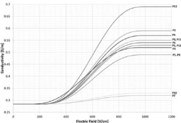
, was defined as a step function increasing from σ0 to σmax over a transition zone of 800 V/cm, centered at 500 V/cm with a contin-uous second derivative. Again, the characteristics of the transition zone were chosen to mimic the function developed for a normal canine pros-tate.13 A parametric study was performed on themaximum electrical conductivity,σmax, to match the calculated current and the maximum meas-ured current during the last set of 10 pulses from the first activated electrode pairing. The first elec-trode pair was chosen for this evaluation to avoid any compounding effects from multiple treat-ments. The current was calculated by performing a surface integration of the normal current den-sity across a cut plane centered between the two active electrodes. Once the patient-specific con-ductivity function was determined (Figure 3), the
solution for the electric field and conductivity dis-tribution were obtained for each electrode pair combination.
Analysis
The current was calculated by integrating the normal current density across a cut plane directly between the first electrode pair to apply treat-ment. A parametric sweep was performed, adjust-ing the maximum conductivity for each patient to match the calculated current to the maximum measured current during the last 10 pulses from the first activated electrode pair. The first elec-trode pair activation was chosen to avoid accu-mulative effects from multiple treatments. Subsequently, the simulation was repeated with the appropriate maximum conductivity.
The ablation zone volumes on whole-mount pathology and MRI were calculated for each patient. The factor in which these volumes dif-fered was determined using the histological abla-tion zone volumes as standard. The exact electric field threshold was determined via volume inte-gration, adjusting the electrical field threshold until the simulated volumes matched the ablation zone volume on histology/MRI. A Mann–Whitney U test was performed in SPSS (version 23) to compare the ablation zone volumes and electrical field thresholds on histology between 3 and 4 electrode configurations.
Results
Patient and procedure characteristics
Of the 16 patients, 3 patients were excluded since >4 needles (n = 1), <3 needles (n = 1) or multi-ple ablations (n = 1) were utilized. The patient characteristics are presented in Table 2. Table 3 summarizes the procedural (electrical) parame-ters as well as the ablation zone volumes on his-tology and MRI for each patient with the corresponding electrical field threshold (n = 13). Figure 3 displays the patient-specific conductivity curves. Figure 4 illustrates a sample electrode registration, treatment protocol, and resulting data for the IRE system that was used for the numerical simulation modeling (Figure 5).
Ablation zone volumes. Table 3 displays the
abla-tion zone volume sizes on whole-mount pathol-ogy and MRI for each patient. The use of four Figure 3. Dynamic conductivity function for
electroporation utilized in each patient-specific simulation. The maximum conductivity was determined parametrically until the calculated electrical current matched the experimental current delivered by the IRE generator.
Table 2. Patient characteristics (n = 13).
Parameter Median (interquartile range)
Age (years) 56 (50–65) Preoperative PSA (ng/ml) 7 (5.3–9.6) Prostate volume (ml) 33 (27–45) Pathological stage pT2c 10 pT3a 3
ISUP on final pathology
ISUP 1 6
ISUP 2 6
ISUP 3 1
ISUP, international society of urological pathology; PSA, prostate-specific antigen.
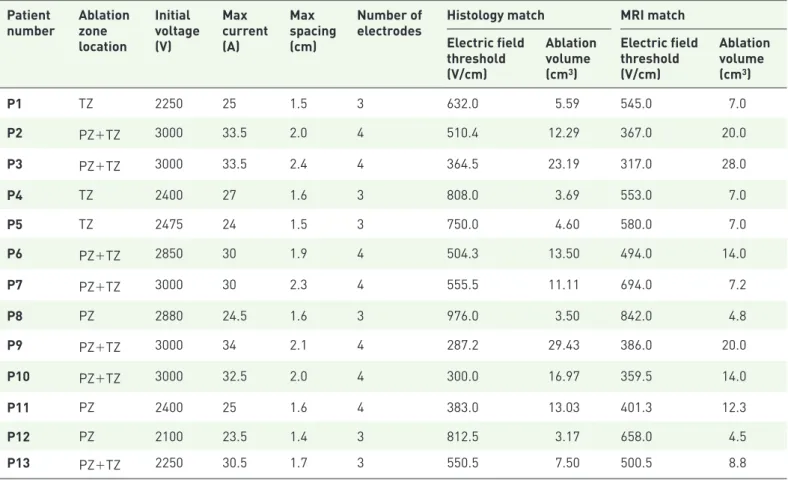
Table 3. The electrical parameters of the procedures are summarized, including the number of electrodes used, potential (range), electrical current (range) and inter-electrode distance (range). The ablation zone volumes on histology and MRI (adjusted for prostate shrinkage) per patient, including the corresponding electrical field threshold.
Patient
number Ablation zone location Initial voltage (V) Max current (A) Max spacing (cm) Number of
electrodes Histology match MRI match Electric field threshold (V/cm) Ablation volume (cm3) Electric field threshold (V/cm) Ablation volume (cm3) P1 TZ 2250 25 1.5 3 632.0 5.59 545.0 7.0 P2 PZ+TZ 3000 33.5 2.0 4 510.4 12.29 367.0 20.0 P3 PZ+TZ 3000 33.5 2.4 4 364.5 23.19 317.0 28.0 P4 TZ 2400 27 1.6 3 808.0 3.69 553.0 7.0 P5 TZ 2475 24 1.5 3 750.0 4.60 580.0 7.0 P6 PZ+TZ 2850 30 1.9 4 504.3 13.50 494.0 14.0 P7 PZ+TZ 3000 30 2.3 4 555.5 11.11 694.0 7.2 P8 PZ 2880 24.5 1.6 3 976.0 3.50 842.0 4.8 P9 PZ+TZ 3000 34 2.1 4 287.2 29.43 386.0 20.0 P10 PZ+TZ 3000 32.5 2.0 4 300.0 16.97 359.5 14.0 P11 PZ 2400 25 1.6 4 383.0 13.03 401.3 12.3 P12 PZ 2100 23.5 1.4 3 812.5 3.17 658.0 4.5 P13 PZ+TZ 2250 30.5 1.7 3 550.5 7.50 500.5 8.8
*Ablation zone location, and location of the ablation zone instead of the zone of the index. PZ, peripheral zone; TZ, transition zone.
Figure 4. Electrode registration in the IRE system, including the inter-electrode distances, as well as the delivered voltage, pulse length and pulse number for each electrode pair. The graphs illustrate the obtained current and administered voltages. Every 10 pulses the IRE system recharges its capacitor bank, which can be seen as a drop in voltage and current. The red arrow indicates the approximate electrical current value used during the derivation of the dynamic conductivity curves.
IRE, irreversible electroporation.
Figure 5. (a) The electrical field [V/cm] and (b) electrical conductivity distribution [S/m] of an IRE treatment in prostate with solid monopolar electrodes. The results are shown in the z–x plane after 90 pulses were applied between each adjacent electrode pair (e23 = 2250 V, e31 = 1950 V, e12 = 1800 V). The electrode exposure was 1.5 cm.
electrodes resulted in significantly larger (p = 0.003) ablation zone volumes [median 13.5 cm2,
interquartile range (IQR) 12.3–23.2 cm2 versus
median 4.1 cm2, IQR 3.4–6.1 cm2] and
conse-quently significantly lower (p = 0.004) electrical field thresholds (median 383 V/cm, IQR 300– 510 V/cm versus median 779 V/cm, IQR 612– 853 V/cm) than of three electrodes, respectively. On average the ablation zone volume was 1.20-times (range 0.65–1.90) larger on MRI compared with the volumes on histology.
Electrical field threshold. The median electrical
field threshold to ablate human (cancerous) pros-tate tissue was 550 V/cm (interquartile range 383– 750 V/cm) for the histology volumes. The median electrical field threshold was 500 V/cm (interquar-tile range 386–580 V/cm) when the ablation zone volumes were used from the follow-up MRI. The electrical field thresholds are summarized in Table 3. Figures 1 and 2 illustrate the three-dimensional ablation zone reconstruction on histology and MRI, respectively.
Discussion
Using the ablation zone volumes on whole-mount prostatectomy and numerical simulation models, we were able to estimate the electrical field thresh-old to ablate human prostate tissue in vivo with IRE. The threshold was lower than previously determined by Neal and colleagues, which may be explained by our larger sample size and three to four electrode configuration.13 Hypothetically, the
use of more electrodes during a particular treat-ment could lead to a greater Joule heating effect, a larger electrical field or ablative effect of IRE, which in turn, may have lowered the threshold. Moreover, the use of more than two needles can create a larger electrical field and ablation volume due to its rela-tionship with the electrode configuration.10
Similarly, our electrical field threshold is lower than the simulation study of Srimathveeravalli and col-leagues, in which the ablation zone volume on T2-weighted and DCE MRI was compared with the simulated electrical field.14 These authors used
a non-inferiority model, decreasing the electrical field treshold stepwise until the simulated volume was statistically non-inferior to the ablation zone volume on MRI. Since our volume integration fol-lowed small steps to obtain similar volumes, the electrical field threshold may have been lower. Our estimated median electric field threshold on T2-weighted MRI was slightly lower than what
was calculated within the study performed by Campelo and colleagues,which calculated an average electric field threshold of 506±66 V/cm for IRE in cancerous human prostate tissue using ablation zone volumes from the 1 week post-treatment MRIs.15 This may be the result
from the use of 4-week post-treatment MRIs fol-lowing IRE. Therefore, the treatment-related edema and inflammation that surrounds the ablation zone on imaging was less than what would be observed upon 1-week post-treatment MRIs, and consequently the ablation zone on the MRI was smaller.18 Currently it is unknown
which of the MRI sequences (T2, DCE or DWI) correlate best with post-treatment ablation zone volumes. This is of importance since when the electrical field is calibrated to a smaller volume, the consequent thresholds are higher.
We showed that the electrical field threshold dif-fered between histology and MRI. This was also due to the differences in ablation zone volumes, as it was previously shown that MRI overestimates the ablation zone volume by a factor of 1.16.19
With the software-generated method we applied, the differences in ablation zone size (cm2) per
con-secutive slide were effaced in order to create a smooth ablation zone surface, thereby generally increasing the size. The range in which the abla-tion zone volumes differed reflects the difficulty in volumetric recontruction, which consequently has an important impact on the simulated outcomes. Furthermore, as can been seen in Figure 3, the conductivity curves differed significantly be-tween patients. This may partly be explained by the heterogeneity of prostate tissue between patients (e.g. a mixture of neoplastic, cystic, fibrotic and glandular tissue). However, our model implies that each electrode pair acted as an individual entity ablating untreated prostate tissue, while in fact the ablation zone for each electrode pair overlaid the ablation zone for other electrode pairs in that simulation. Therefore, the tissue should ideally not be con-sidered untreated and the conductivity analysis should incorporate the impact on the conductiv-ity and tissue by previous electrical pulses between neighboring electrode pairs. This potential interaction required us to exclude one patient that was treated with multiple ablations and one patient that was treated with >4 needles (not every pair was active). In the last case the inter-electrode distance was >2 cm between spe-cific pairs, hindering the delivery of electrical
pulses since it would require too much energy with potential thermal damage. As published before,9 there was no histological effect seen in
the patient that was treated with two electrodes. Another limitation is that our method indirectly incorporated temperature effects by matching the conductivity function to measured values but did not include direct thermal damage to the tissue, nor did it include the cumulative thermal effect, and its subsequent effect on tissue electrical con-ductivity, from other electrode pairs in the three or four-needle configuration. This is particularly of interest for future work, as it has been shown that Joule heating may be an important factor for the ablative effect of IRE.20 These limitations may
explain the observed variance of electrical field thresholds between patients.
Our aim was to validate the results by Neal and colleagues,13 Srimathveeravalli and colleagues14
and Campelo and colleagues,15 using a larger
dataset and applying multiple methods of ablation zone volume analysis. Therefore, our simulation methods were comparable, including the afore-mentioned limitations. It may be important to stress that the electrical field thresholds obtained in this study only apply to procedures that follow the same isoelectric conditions (e.g. electrical pulse length, active tip length, applied voltage). Future optimization of the simulation methods are required before the electrical field threshold may be accurately simulated, especially if these thresholds will be used for treatment-planning models. The three-dimentional simulation of the electrical field, incorporating the effects of previ-ous electroporation by individual needle pairs, the direct (accumulative) effect of Joule heating, patient-specific conductivity between needle pairs and the electrical field threshold changes in response to varying electric conditions (e.g. pulse number, pulse length), may provide a better rep-resentation of the effects of IRE in cancerous prostate tissue.
Conclusion
The electrical field threshold to ablate human prostate tissue in vivo was determined using whole-mount pathology and MRI. These thresh-olds may be used to develop treatment planning or monitoring software for IRE prostate ablation, but further optimization of simulation methods is required to decrease the variance that was observed between patients.
Acknowledgements
We thank C.D. Savci-Heijink for the pathological evaluation and M.R. Engelbrecht for the radio-logical evaluation.
Funding
This work was supported by the Cure for Cancer charity foundation, Cures within Reach and the Endourological Society.
Conflict of interest statement
Scheltema received a PhD grant from the Cure for Cancer charity foundation. De la Rosette and Neal are consultants to AngioDynamics. Arena, Neal and Davalos have pending and issued pat-ents related to the IRE technology.
ORCID iD
Matthijs J. Scheltema https://orcid.org/0000 -0002-9098-9574
References
1. Siegel RL, Miller KD and Jemal A. Cancer statistics, 2017. CA Cancer J Clin 2017; 67: 7–30. 2. Valerio M, Cerantola Y, Eggener SE, et al. New
and established technology in focal ablation of the prostate: a systematic review. Eur Urol 2017; 44: 17–34.
3. Davalos RV, Mir LM and Rubinsky B. Tissue ablation with irreversible electroporation. Ann
Biomed Eng 2005; 33: 223–231.
4. Lee EW, Wong D, Prikhodko SV, et al. Electron microscopic demonstration and evaluation of irreversible electroporation-induced nanopores on hepatocyte membranes. J Vasc Interv Radiol 2012; 23: 107–113.
5. Valerio M, Stricker PD, Ahmed HU, et al. Initial assessment of safety and clinical feasibility of irreversible electroporation in the focal treatment of prostate cancer. Prostate Cancer Prostatic Dis 2014; 17: 343–347.
6. Valerio M, Dickinson L, Ali A, et al. Nanoknife electroporation ablation trial (NEAT): a prospective development study investigating focal irreversible electroporation in men with localised prostate cancer. J Urol 2017; 3: 647–654.
7. Murray KS, Ehdaie B, Musser J, et al. Pilot study to assess safety and clinical outcomes of irreversible electroporation for partial gland ablation in men with prostate cancer. J Urol 2016; 196: 883–890.
8. Ting F, Tran M, Böhm M, et al. Focal irreversible electroporation for prostate cancer: functional outcomes and short-term oncological control.
Prostate Cancer Prostatic Dis 2016; 1: 46–52.
9. van den Bos W, Jurhill RR, de Bruin DM, et al. Histopathological outcomes after irreversible electroporation for prostate cancer: results of an ablate and resect study. J Urol 2016; 196: 552–559.
10. van den Bos W, de Bruin DM, Jurhill RR,
et al. The correlation between the electrode
configuration and histopathology of irreversible electroporation ablations in prostate cancer patients. World J Urol 2016; 34: 657–664. 11. Edd JF and Davalos RV. Mathematical modeling
of irreversible electroporation for treatment planning. Technol Cancer Res Treat 2007; 6: 275–286.
12. Wagstaff PGK, de Bruin DM, van den Bos W, et al. Irreversible electroporation of the porcine kidney: temperature development and distribution. Urol Oncol. Epub ahead of print 31 December 2014. DOI: 10.1016/j. urolonc.2014.11.019.
13. Neal RE, Millar JL, Kavnoudias H, et al. In vivo characterization and numerical simulation of prostate properties for non-thermal irreversible electroporation ablation. Prostate 2014; 74: 458–468.
14. Srimathveeravalli G, Cornelis F, Mashni J, et al. Comparison of ablation defect on MR imaging with computer simulation estimated treatment
zone following irreversible electroporation of patient prostate. Springerplus 2016; 5: 219. 15. Campelo S, Valerio M, Ahmed HU, et al. An evaluation of irreversible electroporation thresholds in human prostate cancer and potential correlations to physiological measurements. APL Bioeng 2017; 1: 016101. 16. van den Bos W, de Bruin DM, Muller BG,
et al. The safety and efficacy of irreversible
electroporation for the ablation of prostate cancer: a multicentre prospective human in vivo pilot study protocol. BMJ Open 2014; 4: e006382. 17. Miklavcic D, Sel D, Cukjati D, et al.
Sequential finite element model of tissue
electropermeabilisation. 26th Annu Int Conf IEEE
Eng Med Biol Soc 2005; 4: 3551–3554.
18. Scheltema MJ, Postema AW, de Bruin DM, et al. Irreversible electroporation for the treatment of localized prostate cancer: a summary of imaging findings and treatment feedback. Diagnostic Interv
Radiol 2017; 23: 365–370.
19. van den Bos W, de Bruin DM, van Randen A,
et al. MRI and contrast-enhanced ultrasound
imaging for evaluation of focal irreversible electroporation treatment: results from a phase I-II study in patients undergoing IRE followed by radical prostatectomy. Eur Radiol 2016; 26: 2252–2260.
20. van Gemert MJC, Wagstaff PGK, de Bruin DM,
et al. Irreversible electroporation: just another
form of thermal therapy? Prostate 2015; 75: 332–335.
Visit SAGE journals online journals.sagepub.com/ home/tau

![Figure 5. (a) The electrical field [V/cm] and (b) electrical conductivity distribution [S/m] of an IRE treatment in prostate with solid monopolar electrodes](https://thumb-eu.123doks.com/thumbv2/9libnet/5439921.104300/7.892.126.665.534.946/electrical-electrical-conductivity-distribution-treatment-prostate-monopolar-electrodes.webp)
