1 2 3 4 5 6 7 8 9 10 11 12 13 14 15 16 17 18 19 20 21 22 23 24 25 26 27 28 29 30 31 32 33 34 35 36 37 38 39 40 41 42 43 44 45 46 47 48 49 50 51 52 53 54 55 56 57
Atomic Layer Deposition of Pd Nanoparticles on N-Doped
Electrospun Carbon Nanofibers: Optimization of ORR Activity of
Pd-Based Nanocatalysts by Tuning Their Nanoparticle Size and
Loading
Mohammad Aref Khalily,*
[a, b]Bhushan Patil,
[a]Eda Yilmaz,
[a]and Tamer Uyar*
[a, c] Abstract: Optimization of size, loading and chemicalcompo-sition of catalytic nanoparticles is a crucial step to achieve cost-effective and efficient (electro) catalysts. This report elaborates optimization of palladium (Pd) nanoparticle size and loading on the electrospun based N-doped carbon nanofibers (nCNF) towards oxygen reduction reaction (ORR) for the energy devices like fuel cell, metal air batteries. Electrospinning was utilized to produce one-dimensional (1D) polyacrylonitrile nanofibers followed by a two-step carbon-ization process obtaining well-defined conductive nCNF having diameters in the range of 200–350 nm. As-synthesized nCNF was decorated with discrete Pd nanoparticles ranging
from 2.6 � 0.4 nm to 4.7 � 0.5 nm via thermal atomic layer deposition (ALD) technique. We found that nCNF deposited Pd nanoparticles having 3.9 � 0.6 nm size (Pd20/nCNF) showed the best ORR activity with the smallest Tafel slope of 58 mV dec 1
along with four electrons involved in the ORR. In addition, high value at half wave potential (E1/2=806 mV vs. RHE) and exchange current densities (i0=6.998 mA cm 2) at Pd20/nCNF makes it efficient catalyst among other Pd decorated nCNF. Moreover, we found that electrocatalyst with lower loading/density of Pd nanoparticles showed enhanced ORR activity.
Introduction
Extensive research has been devoted to fuel cell materials and fuel cell systems as clean and efficient power source, which could directly transform chemical energy into electric energy.[1] Oxygen reduction reaction (ORR), an important cathodic reaction, lies in the heart of direct liquid (methanol, ethanol, or formic acid) fuel cells and metal-air batteries.[2]
Currently, platinum (Pt)-based nanomaterials are considered as the most effective catalyst to drive kinetically sluggish oxygen reduction reaction.[3]
However, its industrial scale usage is limited due to high cost and low abundance of Pt metal. Therefore, enormous effort has been put in replacing precious Pt metal with relatively cheaper materials including but not limited to palladium (Pd),[2] carbon,[4]
nickel,[5] iron[6]
and cobalt.[7]
Among the aforemen-tioned electrocatalysts, Pd based nanomaterials have been
shown to be a promising potential candidate in replacing Pt electrocatalysts.[2]
Several research studies have been conducted on development of novel electrocatalysts for ORR. On the other hand, less attention has been given to optimization of size, loading and distribution of electrocatalytic nanoparticles for ORR.[8]
Lowering amount of electrocatalyst or increasing the mass activity of electrocatalyst is highly desirable for the commercialization of the polymer electrolyte fuel cell (PEMFC), perovskites and metal air batteries.[9]
Mass activity of catalyst directly influences PEMFC[10]
and metal air batteries.[11] To achieve the highest catalytic activity of ORR with less amount of catalyst is necessary to obtain high mass activity. Thus, optimization of Pd size and loading is a crucial step to have maximum catalytic activity.
Atomic layer deposition (ALD) is a thin film deposition technique which utilizes self-limiting chemical reactions be-tween gaseous metallorganic precursors and support surfaces to grow extremely uniform and exceptionally conformal thin films of metals, metal oxides, sulfides and nitrides.[12] ALD technique allows deposition different materials in highly controlled, conformal and reproducible manner. Moreover, ALD have been increasingly utilized in synthesizing well-defined metallic,[13]bimetallic[14]and core-shell[15]nanocatalysts. ALD has become one of the most promising approaches in preparation of thin films and nanomaterials due to its high reproducibility, precise control over size, shape and composition of the nanomaterials.[16] Another versatile bottom-up nanofabrication technique for the production of 1D nanofibers is electro-spinning. Electrospinning is a versatile and cost-effective technique for the production of nanofibers from variety of materials such as polymers, ceramics, supramolecular structures, and etc.[17]This versatile and cost-effective technique allows fine [a] Dr. M. A. Khalily, Dr. B. Patil, Dr. E. Yilmaz, Prof. T. Uyar
Institute of Materials Science & Nanotechnology Bilkent University
Ankara 06800 (Turkey) [b] Dr. M. A. Khalily
Laboratory of Biomolecular Nanotechnology MESA + Institute for Nanotechnology University of Twente
Enschede 7500 AE (The Netherlands) E-mail: [email protected] [c] Prof. T. Uyar
Department of Fiber Science & Apparel Design College of Human Ecology
Cornell University
Ithaca, New York 14853 (United States) E-mail: [email protected]
Supporting information for this article is available on the WWW under https://doi.org/10.1002/cnma.201900483
1 2 3 4 5 6 7 8 9 10 11 12 13 14 15 16 17 18 19 20 21 22 23 24 25 26 27 28 29 30 31 32 33 34 35 36 37 38 39 40 41 42 43 44 45 46 47 48 49 50 51 52 53 54 55 56 57
tuning of the chemical composition, morphology, size, porosity, and surface area of electrospun nanofibers.[17a]
Electrospinning has been widely exploited in fabrication of various catalysts and electrocatalysts.[18]
In present work, we exploited the advantages of two bottom-up nanofabrication techniques namely electrospinning and ALD to optimize Pd nanoparticle size and loading on the N-doped electrospun carbon nanofibers for ORR. Electrospinning was utilized for fabrication of polyacrylonitrile (PAN) nanofibers followed by two-step carbonization process to obtain conduc-tive N (nitrogen)-doped carbon nanofibers (nCNF). As-synthe-sized nCNF was further decorated with well-defined Pd nano-particles (Pd/nCNF) ranging from 2.6 � 0.4 nm to 4.7 � 0.5 nm via thermal ALD technique. Pd cycles of 10 (Pd10/nCNF), 20 (Pd20/nCNF), 30 (Pd30/nCNF) and 40 (Pd40/nCNF) produced Pd nanoparticles having 2.6 � 0.4 nm, 3.9 � 0.6 nm, 3.8 � 0.5 nm and 4.7 � 0.5 nm size, respectively. We found that nCNF deposited Pd nanoparticles having 3.9 � 0.6 nm (Pd20/nCNF) size showed the best ORR activity with the smallest Tafel slope of 58 mV dec 1
. In addition, high value at half wave potential (E1/2=806 mV vs. RHE) and exchange current densities (i0= 6.998 mA cm 2
) at Pd20/nCNF makes it most efficient electro-catalyst among Pd10/nCNF, Pd30/nCNF and Pd40/nCNF. In addition to the influence of Pd nanoparticle size, effect of loading or density of Pd nanoparticles was realized by controlled size (i. e. ~ 4 nm) ALD deposited Pd nanoparticles with different densities. We found that Pd20/nCNF electro-catalyst with lower loading of Pd nanoparticles than Pd30/nCNF showed enhanced ORR activity.
Results and Discussion
It is well-known that both conductivity and N-doping of carbon fibers has significant impact on the ORR.[19]
To this end, we performed electrospinning to produce polyacrylonitrile (PAN) electrospun nanofibers (Figure 1a) as imaged by scanning electron microscopy (SEM). As-synthesized PAN electrospun nanofibers were converted into nCNF by a two-step carbon-ization process. First, the PAN nanofibers were stabilized at 280°C under air atmosphere followed by cooling to room temperature. Ultimately, stabilized PAN nanofibers were carbon-ized into nCNF by heating the sample at 800°C under inert condition (argon).[7b,13a] We clearly observed formation of uni-form 1D nCNF having diameters in the range of 200–350 nm (Figure 1b). As expected, the diameters of PAN electrospun nanofibers shrank from 500–300 nm to 200–350 nm after carbonization process.
We conducted X-ray photoelectron spectroscopy (XPS) to investigate chemical composition of nCNF. The survey XPS spectrum of nCNF (Figure 1c) displays presence of carbon (C), nitrogen (N) and oxygen (O) species. We further performed elemental (CHNS O) analysis to quantify the chemical composi-tion of nCNF. Elemental analysis results estimated that nCNF is consisted of 71.3% C, 14.4% N, 13.2% O and 1.1% H species. Presence of N species plays a vital role in stabilizing and anchoring of metallic nanoparticles on the carbon supports and
also chemical nature of these N species has crucial impact on ORR activity.[19]
Therefore, we conducted high resolution XPS to determine different chemical states of N species both qual-itatively and quantqual-itatively. The deconvoluted N 1s spectrum of nCNF(Figure 1d) demonstrates the existence of four different N species including pyridinic (397.9 eV), nitrile (399.6 eV), quater-nary(400.9 eV) and oxidized (403.0 eV) nitrogen.[7b]
We also analyzed nCNF by powder X-ray diffraction (XRD) displaying large interlayer distance between the graphene sheets (002 planes) which can be ascribed to characteristic patterns of turbostratic carbon (Figure S1).[13a]
Lastly, we utilized BET analysis (Figure S2) to calculate the surface area of nCNF as 63 m2
g 1 .
After fully characterizing chemical structure of nCNF by means of multiple techniques, we exploited thermal ALD to grow well-defined, well-dispersed and discrete Pd nanoparticles on nCNF support. A minute amount (~ 10 mg) of nCNF was spread on a clean silicon wafer then sequential dosing of Pd (hfac)2(hfac = hexafluoroacetylacetonate) precursor and formal-in lead to formation of desired Pd nanoparticles at 200°C
(Figure 2).[20] The scanning transmission electron microscopy (STEM) images (Figure 2) evidently reveals the successful decoration of nCNFs with Pd nanoparticles. We prepared four different samples which are consisted of 10 (Pd10/nCNF), 20 (Pd20/nCNF), 30 (Pd30/nCNF) and 40 (Pd40/nCNF) Pd ALD cycles. Average size of nanoparticles was calculated as 2.6 � 0.4 nm, 3.9 � 0.6 nm, 3.8 � 0.5 nm and 4.7 � 0.5 nm for Pd10/ nCNF, Pd20/nCNF, Pd30/nCNF and Pd40/nCNF, respectively. We also clearly noticed the increase of population of Pd nano-particles on nCNF as the number of Pd deposition cycles is increased (Figure 2a-d). Existence of Pd nanoparticles on nCNFs was further confirmed by energy dispersive X-ray spectroscopy-STEM (EDS-spectroscopy-STEM) (Figure S3).
To gain insight into crystallinity of ALD technique grown Pd nanoparticles, we conducted powder X-ray diffraction (XRD) Figure 1. SEM images of electrospun PAN nanofibers (a) and nCNF produced at 800°C (b). Survey XPS spectrum (c), and deconvoluted XPS spectrum of N1s of nCNF (d).
1 2 3 4 5 6 7 8 9 10 11 12 13 14 15 16 17 18 19 20 21 22 23 24 25 26 27 28 29 30 31 32 33 34 35 36 37 38 39 40 41 42 43 44 45 46 47 48 49 50 51 52 53 54 55 56 57 analysis of Pd10/nCNF, Pd20/nCNF, Pd30/nCNF, and Pd40/nCNF samples (Figure 3a). Owing to lower loading and smaller size of Pd nanoparticles for Pd10/nCNF and Pd20/nCNF, we could not get any meaningful signals associated to crystalline phases of Pd (Figure 3a). On the other hand, weak signals are clearly
visible for Pd30/nCNF and Pd40/nCNF which can be attributed to (111) lattice phase of Pd.[21]
Moreover, high resolution TEM (HRTEM) analysis of Pd20/nCNF explicitly evidenced the (111) facet orientation of Pd nanocrystals (Figure S4).[20]
We further investigated the chemical composition and states of ALD deposited Pd species by high resolution XPS of Pd/nCNF samples (Figure 3b and Figure S5a-d). The deconvolu-tion of Pd 3d for Pd20/nCNF (Figure 3b) displays spin-orbit splitting into 3d3/2and 3d5/2 components with mixed oxidation states of Pd2 +
/Pd0 .[20]
Lastly, we determined the loading of Pd as 0.324% (Pd10/nCNF), 0.524% (Pd20/nCNF), 0.989% (Pd30/nCNF), and 1.06% (Pd40/nCNF) using inductively coupled plasma-mass spectroscopy (ICP-MS). As the number of ALD cycles increased, loading of the Pd was also increased which was also supported by STEM images (Figure 2a–d) and XRD (Figure 3a) results.
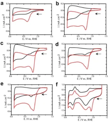
The cyclic voltammetry (CV) measurements obtained at the nCNF, Pd10/nCNF, Pd20/nCNF, Pd30/nCNF, Pd40/nCNF, and Pt/ C under N2and O2saturated 0.1 M KOH solution is shown in the Figure 4. The CV measurements at bare nCNF show ORR activity with cathodic onset potential of ca. 750 mV while Pd loaded nCNF samples demonstrate higher onset potentials. The hydro-gen adsorption and desorption peaks in the Pd10/nCNF, Pd20/ nCNF, Pd30/nCNF, and Pd40/nCNF were not prominent, it might be due to the fact that OH in the KOH solution inhibit the hydrogen adsorption and desorption on the Pd nanoparticles.[8b]
Therefore, intensity of the Pd-oxide reduction peak at the 720 mV (Figure 4b-e, black line) considered as the representative of Pd loading during different ALD cycles. An increase in the current density of Pd-oxide reduction peak from the Pd10/nCNF to Pd40/nCNF is expected due to high loading Figure 2. STEM images of Pd10/nCNF (a), Pd20/nCNF (b), Pd30/nCNF (c), and
Pd40/nCNF (d).
Figure 3. XRD of Pd/nCNF samples (a) and deconvoluted XPS spectra of Pd3d for Pd20/nCNF (b)
Figure 4. CV measured at nCNF (a), Pd10/nCNF (b), Pd20/nCNF (c), Pd30/ nCNF (d), Pd40/nCNF (e), Pt/C (f) under N2(black) and O2(red) saturated
1 2 3 4 5 6 7 8 9 10 11 12 13 14 15 16 17 18 19 20 21 22 23 24 25 26 27 28 29 30 31 32 33 34 35 36 37 38 39 40 41 42 43 44 45 46 47 48 49 50 51 52 53 54 55 56 57
of Pd as the number of ALD cycles increased from 10 to 40. The electrochemically active surface areas measured based on the charge of Pd-oxide reduction peak from the CV obtained at Pd10/nCNF, Pd20/nCNF, Pd30/nCNF, and Pd40/nCNF were 0.023, 0.23, 1.74, and 3.87 cm 2
, respectively (the standard charge of the Pd electrode is 405 μC cm 2
).[8b]
Furthermore, increase in the non-Faradic current from the Pd10/nCNF to Pd40/nCNF infers enhancement in the capacitive layer which can be directly correlated with the increase in the area. Therefore, it is expected that ORR should enhance as the Pd loading increases i. e. increase in the ALD cycles. To select the Pd loading for an efficient ORR catalysis, onset potential (i. e. the potential required to initiate the ORR) is one of the most important criteria in the selection of ORR electrocatalysts. Among the different ALD cycle deposited Pd; Pd10/nCNF has most cathodic onset potential whereas Pd20/nCNF, Pd30/nCNF, and Pd40/nCNF have almost same onset potential which is ca. 20 mV anodic to the Pd10/nCNF. ORR is one of the crucial steps in the fuel cell and metal air batteries both of which require light material catalysts to design light weight energy devices. Thus, mass activity of these catalysts was measured by dividing current densities with the mass of catalyst (obtained from the ICP-MS). Although, mass activity of Pd10/nCNF is highest among all the Pd deposited catalysts, it is clear from the onset potential of ORR that the Pd10/nCNF requires 20 mV higher potential than the Pd20/nCNF. In case of the Pd30/nCNF and Pd40/nCNF onset potential of ORR remains close to the Pd20/ nCNF however mass activity decreased drastically (Table 1). Thus, Pd20/nCNF has anodic onset potential with high mass activity which clearly implies that optimization of ALD cycles and size of Pd nanoparticles affect the ORR catalysis. The effect of Pt catalyst particle size towards ORR has been well-known;[22] in the same context, we anticipate that the size of Pd nanoparticles would influence the ORR catalysis. As reported by the Anastasopoulos et. al. the diameter of Pd nanoparticles increased from 1 nm to 7 nm resulted in an anodic shift in the onset potential of the ORR.[8a]
Onset potential remained almost constant at the Pd nanoparticles above the size of 7 nm. In the same context, our findings shows that less than 3 nm diameter Pd nanoparticles loaded nCNF (i. e. Pd10/nCNF) is more cathodic to the 3–5 nm diameter Pd nanoparticles loaded nCNF(i. e. Pd20/nCNF, Pd30/nCNF and Pd40/nCNF). The onset potential of
ORR at the Pd20/nCNF, Pd30/nCNF and Pd40/nCNF remains almost constant which slightly differs from the reported values i. e. an anodic shift in the onset potential was not observed as the Pd particle size increased from 3 to 5 nm.[8a]
Thus, in addition to particle size other factors like facet of Pd and distribution of Pd nanoparticles are also important in the ORR catalysis.[23]
Electrocatalytic activity of ORR obtained at the nCNF, Pd10/ nCNF, Pd20/nCNF, Pd30/nCNF, Pd40/nCNF, and Pt/C samples was analyzed with RDE measurements from 100 to 1600 rpm with the scan rate of 10 mV s 1
in the O2saturated KOH solution (Figure S6). This RDE data is used for the Koutecky-Levich plots at the steady state currents which are shown in Figure S7. The number of electrons involved in the ORR per oxygen molecule is another important criterion to assess the ORR catalysts. It was determined from the slope using Koutecky-Levich equitation:[24] 1=j ¼ 1=jkþ1=jL¼1=jkþ1=ðBw1=2Þ (1)
where B = 0.62nFCD2/3 v 1/6
, jk is the kinetic current density, j is
the measured current density, jLis the Levich current density, n
is the number of electrons transferred per oxygen molecule, F is the Faraday constant i. e. 96,485 C mol 1
, C is the dissolved oxygen concentration in the solution (1.26 × 10 6
mol cm 3 ), v is the kinematic viscosity of the solution (1.009 × 10 2
cm2 s 1
), D is the diffusion coefficient of oxygen (2.1 × 10 5
cm2 s 1
) and ω is the rotation rate (rad s 1
).[10,6]
Assuming a four-electron reaction and the known geometric electrode surface area, the theoretical slope B is 2.5 cm2
rad1/2 mA1
s 1/2
. The number of electrons has trend as Pd10/nCNF > Pd20/nCNF > Pd30/nCNF > Pd40/nCNF > nCNF. To find out kinetics of ORR at these catalysts, the kinetic current density was calculated from equation (2) and used to estimate Tafel slope (Figure 5). Based on the slope and constant obtained from the straight line of log jkvs. potential were used
to estimate Tafel slope and the exchange current density (i0), respectively.
Jk¼ ðj � jLÞ=ðjL jÞ (2)
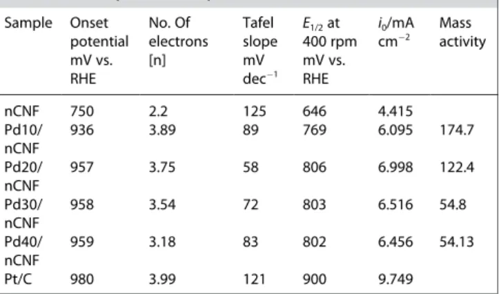
Table 1. Summary of ORR catalysts in 0.1 M KOH Sample Onset potential mV vs. RHE No. Of electrons [n] Tafel slope mV dec1 E1/2at 400 rpm mV vs. RHE i0/mA cm 2 Mass activity nCNF 750 2.2 125 646 4.415 Pd10/ nCNF 936 3.89 89 769 6.095 174.7 Pd20/ nCNF 957 3.75 58 806 6.998 122.4 Pd30/ nCNF 958 3.54 72 803 6.516 54.8 Pd40/ nCNF 959 3.18 83 802 6.456 54.13 Pt/C 980 3.99 121 900 9.749
Figure 5. Tafel slope obtained at the nCNF, Pd10/nCNF, Pd20/nCNF, Pd30/ nCNF, Pd40/nCNFand Pt/C under O2saturated 0.1 M KOH (Data used from
1 2 3 4 5 6 7 8 9 10 11 12 13 14 15 16 17 18 19 20 21 22 23 24 25 26 27 28 29 30 31 32 33 34 35 36 37 38 39 40 41 42 43 44 45 46 47 48 49 50 51 52 53 54 55 56 57
All these important catalytic properties are summarized in the Table 1. The small value of Tafel slope obtained at Pd20/ nCNF (i. e. 58 mV dec 1
) shows its kinetically enhanced ORR catalytic activity with the second step as the rate limiting step. In addition, high value at half wave potential (E1/2=806 mV vs. RHE) and exchange current densities (i0=6.998 mA cm 2) at Pd20/nCNF makes it efficient catalyst among these Pd deco-rated nCNF. The mass activity trend is similar with the number of electrons involved in the ORR. However, Pd10/nCNF has cathodic onset potential towards ORR; in other words, it needs more potential to initiate ORR than the Pd20/nCNF. In addition, Pd10/nCNF has low value of half wave potential, exchange current density in comparison with the Pd20/nCNF, which implies that ORR process is slowed down at the small sized Pd nanoparticles loaded nCNF. It can be assigned to the oxophilic nature of small sized Pd nanoparticles which adsorb the OH from the KOH solution which can be correlated with the Pt nanoparticles.[8b]
Furthermore, high half wave potential, ex-change current density, low Tafel value at Pd20/nCNF made it better catalyst towards ORR than the Pd30/nCNF and Pd40/ nCNF. The onset potential at the Pd20/nCNF and number of electrons involved in the ORR were close to the commercial Pt/ C catalyst.
It is clearly noticed that although sizes of Pd nanoparticles in the Pd20/nCNF and Pd30/nCNF are close to 4 nm, they show difference in the ORR catalysis. The Pd nanoparticle loading is different in Pd20/nCNF and Pd30/nCNF. Thus, we can conclude that in addition to particle size, loading or density of nano-particles influence the ORR catalysis.[25]
The loading of Pd nanoparticles is higher in Pd30/nCNF than the Pd20/nCNF. In other words, Pd nanoparticles are closer to each other in the Pd30/nCNF than the Pd20/nCNF. The slow ORR kinetics obtained for Pd30/nCNF might be due to surface coverage by the intermediate products (H2O2 or OH ) formed during ORR. However, in the case of Pd20/nCNF, such deposited products can spillover on the nCNF keeping the Pd nanoparticles surface clean for the further ORR.[26]
Such a spillover might be restricted due to dense Pd nanoparticles in the Pd30/nCNF, which might be the rationale of slow ORR for the Pd30/nCNF than the Pd20/ nCNF, thus proving the importance of the loading Pd of nanoparticles in addition to their sizes. Another possibility of Pd nanoparticle aggregation or Ostwald-ripening during the ORR measurement at the Pd30/nCNF cannot be over ruled which is less expected in the Pd20/nCNF due to low density of Pd nanoparticles (i. e. distance between two Pd nanoparticles is higher in the Pd20/nCNF than the Pd30/nCNF).[27]
Conclusion
In summary, electrospinning was utilized to produce polyacrylo-nitrile nanofibers followed by a two-step carbonization process for obtaining conductive nCNF having diameters in the range of 200–350 nm. As-synthesized nCNF was decorated with discrete Pd nanoparticles ranging from 2.6 � 0.4 nm to 4.7 � 0.5 nm via thermal ALD technique. Initiation of ORR at less potential in other words anodic shift in the onset potential, without
producing H2O2or 4 electrons ORR, and small Tafel slope values are crucial for the efficient ORR catalysis. Considering these, Pd20/nCNF showed the best electrocatalytic ORR activity among the different ALD coated Pd particles. This research work underlines the importance of nanoparticle size and loading of Pd for ORR. Present research work can be further extended by producing more conductive, high porosity and high surface area N-doped electrospun nanofibers. Plasma assisted ALD using H2and O2can be used to obtain high purity metallic Pd nanoparticles. This work will open new possibilities for fabrication of novel electrocatalysts in highly controlled manner for applications in ORR and OER electrocatalysis.
Experimental Section
Materials
Polyacrylonitrile (PAN, Mw � 150000 g mol 1) was purchased from
Scientific Polymer Products, Inc. Dimethylformamide (DMF), 20% Platinum on graphitized carbon (< 5 nm (Pt); Pt/C) were purchased from Sigma-Aldrich and KOH from Alfa Asesar. Palladium (II) hexafluoroacetylacetonate (Pd(hfac)2 and formalin were purchased from Strem Chemicals and Sigma-Aldrich, respectively. All chem-icals were used as received and without further purification.
Synthesis of Electrospun PAN and Electrospun Carbon Nanofibers (nCNF)
To produce polyacrylonitrile electrospun fibers (PAN, Mw �150000 g mol 1), 13% (w/v, with respect to solvent) polymer
solution was prepared in DMF at 50°C. After cooling down the viscous and transparent PAN solution was loaded into a 3 mL syringe having needle of 0.4 mm inner diameter. Flow rate was adjusted as 0.5 mL/h by a pump (KD Scientific, KDS 101) and a voltage of 15 kV was applied by high voltage power supply (Matsusada, AU Series) for electrospinning process. The PAN nano-fibers was collected on aluminum foil as a web. Before the carbonization, electrospun PAN nanofibers were dried in fume hood for 72 h to get rid of residual solvent. To convert PAN electrospun nanofibers into carbon nanofibers (nCNF), electrospun PAN nanofibers was heated up to 280°C at heating rate of 1°C/min and holding for 1 h under air flow in a furnace. The stabilized PAN nanofibers were allowed to cool down to room temperature followed by passing Ar gas (100 sccm) for 30 minutes. Eventually stabilized sample was carbonized at 800°C under inert (Ar) environ-ment along with heating rating of 5°C/min and keeping for 1.5 h at 800°C.
Characterization of PAN Nanofibers and nCNF
FEI Quanta 200 FEG environmental scanning electron microscope was utilized to visualize morphology of electrospun PAN nanofibers and nCNF. Electrospun PAN nanofibers were sputter coated with 5 nm of gold/palladium prior to imaging. To quantify the composition of nCNF, 2 mg of sample (nCNF) plus 8 mg of vanadium (V) oxide (catalyst) were loaded into a tin container. Calibration curves were obtained using BBOT (2, 5-(bis (5-tert-butyl-2-benzo-oxazol-2-yl)) thiophene as standard calibrations. The meas-urements were performed by Thermo Scientific FLASH 2000 series CHNS O analyzer. A small amount of nCNF (~ 50 mg) was weighed into an analysis tube and degassed under high vacuum at 80°C for 720 min. The analysis was conducted after reweighing the degassed
1 2 3 4 5 6 7 8 9 10 11 12 13 14 15 16 17 18 19 20 21 22 23 24 25 26 27 28 29 30 31 32 33 34 35 36 37 38 39 40 41 42 43 44 45 46 47 48 49 50 51 52 53 54 55 56 57
sample. The Brunauer-Emmett-Teller (BET) surface areas were determined from N2adsorption isotherms by multipoint analysis.
Synthesis and Characterization of Pd/nCNF
Pd nanoparticles were decorated on nCNF using a Savannah S100 ALD reactor (Ultratech Inc.). Approximately 10 mg of nCNF was dispersed in ethanol and loaded on silicon wafer substrate and was dried at room temperature. Pd(hfac)2 and formalin (HCOH, 30% in aqueous solution with 15% methanol) were used as Pd precursor and as counter reactant respectively. The Pd precursor was preheated to 70°C to obtain a proper vapor pressure. N2was used
as carrier gas with flow rate of 20 sccm. Pd nanoparticles were grown at 200°C. Pd/nCNF samples were fixed copper tape then were analyzed by Thermo K-alpha monochromatic high perform-ance X-ray photoelectron spectrometer. High resolution XPS were obtained with 50 scans. Pass energy, step size and spot size were adjusted as 30 eV, 0.1 eV and 400 μm, respectively. X-ray Diffraction analysis was perfumed for Pd/nCNF samples by PANalytical X’Pert Powder Diffractometer. All data were recorded by using CuKα radiation in the range of 2θ = 10°–80°. FEI Tecnai G2 F30 trans-mission electron microscope (TEM) was utilized to obtain both TEM and HRTEM images of Pd/nCNF samples. Small amount of samples were first dispersed in ethanol followed by loading 10 μl of the mixture on carbon grid. 2 mg of Pd/nCNF samples were digested in 4 mL of aqua regia for 4 days. Standards of Pd having 500 ppb, 250 ppb, 125 ppb and 62.5 ppb concentrations were prepared in 2% solution of HNO3: HCl (1 : 1) for calibration curve. 2% solution of
HNO3: HCl (1 : 1) was used as a blank. Pd/nCNF in Aqua regia was
passed through cellulose filter to get rid of undissolved nCNF and then was diluted ~ 100 times by 2% solution of HNO3 : HCl (1 : 1) for ICP-MS analysis. Thermo X series II inductively coupled plasma-mass spectrometer was used to record the measurements. The ICP-MS operating parameters were: dwell time – 10 000 ms, channel per mass – 1, acquisition duration – 7380, channel spacing – 0.02, carrier gas-argon.
Electrochemical Measurements
All experiments were performed at room temperature at the Biologic SP-150 Potentiostat with the standard three-electrode electrochemical cell. The catalyst modified glassy carbon electrode (GC, 3 mm diameter, 0.07068 cm2 of geometric surface area), Pt
spiral wire and Ag j AgCl j KCl(sat.)were used as working, counter and
reference electrodes, respectively. The ORR were performed in 20 ml 0.1 M KOH solution where prior to each measurement the electrolyte solution was saturated with either N2or O2gas (99.999%
of purity) for 45 min. Rotating disk electrode (RDE) linear sweep voltammetry (LSV) technique was to determine ORR mechanism and kinetics. The Nernst equation (SE1) used to convert all the potentials measured vs. Ag j AgCl j KCl(sat.)to the reversible hydrogen
electrode (RHE)7:
ERHE¼EAgjAgCljKClðsat:Þþ0:059 pH þ E�
AgjAgCljKClðsat:Þ (SE1)
Where ERHEis potential estimated vs. RHE, EAg j AgCl j KCl(sat.)is measured
potential vs. Ag j AgCl j KCl(sat.) electrode and E°Ag j AgCl j KCl(sat.) is the
standard electrochemical potential of the Ag j AgCl j KCl(sat.)electrode
i. e. 197 mV.
The electrocatalyst slurries were prepared by mixing 8 mg catalyst (nCNF, Pd10/nCNF, Pd20/nCNF, Pd30/nCNF, Pd40/nCNF, PtC) in the 500 μL of DI water, 100 μL of ethanol and 40 μL of 5 wt% Nafion solution followed by vortex for 10 min. The GC surface was cleaned with aqueous slurries of consecutively finer alumina powder (1 μm
down to 0.06 μm) with the help of a polishing micro cloth. To remove the alumina, the electrode was ultrasonically cleaned in the 18 MΩ Millipore water followed by ethanol for 10 min, individually. To fabricate nCNF, Pd10/nCNF, Pd20/nCNF, Pd30/nCNF, Pd40/nCNF, and Pt/C modified GC, 4 μL electrocatalyst slurry was drop casted on cleaned GC, individually. The loading is well above to obtain four-electron ORR (i. e. 200 mg cm 1). Thus prepared electrodes
were dried in an oven at 60°C for 30 min prior to electrochemical measurements. All the calculations were measured based on the geometric surface area unless specified.
Conflict of Interest
The authors declare no conflict of interest.
Keywords: nanocatalysis · atomic layer deposition · electrospining · electrocatalysis · oxygen reduction reaction
[1] C. Y. Wang, Chem. Rev. 2004, 104, 4727–4765.
[2] M. Shao, Q. Chang, J. P. Dodelet, R. Chenitz, Chem. Rev. 2016, 116, 3594– 3657.
[3] a) S. Dai, J. P. Chou, K. W. Wang, Y. Y. Hsu, A. Hu, X. Pan, T. Y. Chen, Nat. Commun. 2019, 10, 440; b) C. Kim, F. Dionigi, V. Beermann, X. Wang, T. Moller, P. Strasser, Adv. Mater. 2018, e1805617.
[4] a) L. Dai, Y. Xue, L. Qu, H. J. Choi, J. B. Baek, Chem. Rev. 2015, 115, 4823– 4892; b) X. Liu, Y. Zhou, W. Zhou, L. Li, S. Huang, S. Chen, Nanoscale 2015, 7, 6136–6142.
[5] a) V. Vij, S. Sultan, A. M. Harzandi, A. Meena, J. N. Tiwari, W.-G. Lee, T. Yoon, K. S. Kim, ACS Catal. 2017, 7, 7196–7225; b) B. Patil, B. Satilmis, M. A. Khalily, T. Uyar, ChemSusChem 2019, 12, 1469–1477.
[6] H. Zhang, S. Hwang, M. Wang, Z. Feng, S. Karakalos, L. Luo, Z. Qiao, X. Xie, C. Wang, D. Su, Y. Shao, G. Wu, J. Am. Chem. Soc. 2017, 139, 14143– 14149.
[7] a) Y. Liang, Y. Li, H. Wang, J. Zhou, J. Wang, T. Regier, H. Dai, Nat. Mater. 2011, 10, 780; b) M. A. Khalily, B. Patil, E. Yilmaz, T. Uyar, Nanoscale 2019, 1, 1224–123Nanoscale1.
[8] a) A. Anastasopoulos, J. C. Davies, L. Hannah, B. E. Hayden, C. E. Lee, C. Milhano, C. Mormiche, L. Offin, ChemSusChem 2013, 6, 1973–1982; b) L. Jiang, A. Hsu, D. Chu, R. Chen, J. Electrochem. Soc. 2009, 156, B643-B649; c) T. Mittermeier, A. Weiss, H. A. Gasteiger, F. Hasche, J. Electrochem. Soc. 2017, 164, F1081-F1089.
[9] a) H. A. Gasteiger, S. S. Kocha, B. Sompalli, F. T. Wagner, Appl. Catal. B 2005, 56, 9–35; b) B. Lim, M. J. Jiang, P. H. C. Camargo, E. C. Cho, J. Tao, X. M. Lu, Y. M. Zhu, Y. N. Xia, Science 2009, 324, 1302–1305; c) J. Suntivich, H. A. Gasteiger, N. Yabuuchi, H. Nakanishi, J. B. Goodenough, Y. Shao-Horn, Nat. Chem. 2011, 3, 546–550.
[10] F. Jaouen, E. Proietti, M. Lefevre, R. Chenitz, J. P. Dodelet, G. Wu, H. T. Chung, C. M. Johnston, P. Zelenay, Energy Environ. Sci. 2011, 4, 114–130. [11] a) F. Y. Cheng, J. Chen, Chem. Soc. Rev. 2012, 41, 2172–2192; b) M. F.
Tovini, B. Patil, C. Koz, T. Uyar, E. Yilmaz, Nanotechnology 2018, 29. [12] a) S. M. George, Chem. Rev. 2010, 110, 111–131; b) R. W. Johnson, A.
Hultqvist, S. F. Bent, Mater. Today 2014, 17, 236–246.
[13] a) M. A. Khalily, M. Yurderi, A. Haider, A. Bulut, B. Patil, M. Zahmakiran, T. Uyar, ACS Appl. Mater. Interfaces 2018, 10, 26162–26169; b) M. A. Khalily, H. Eren, S. Akbayrak, H. H. Susapto, N. Biyikli, S. Ozkar, M. O. Guler, Angew. Chem. Int. Ed. Engl. 2016, 55, 12257–12261.
[14] S. T. Christensen, H. Feng, J. L. Libera, N. Guo, J. T. Miller, P. C. Stair, J. W. Elam, Nano Lett. 2010, 10, 3047–3051.
[15] S. F. Xie, S. I. Choi, N. Lu, L. T. Roling, J. A. Herron, L. Zhang, J. Park, J. G. Wang, M. J. Kim, Z. X. Xie, M. Mavrikakis, Y. N. Xia, Nano Lett. 2014, 14, 3570–3576.
[16] B. J. O’Neill, D. H. K. Jackson, J. Lee, C. Canlas, P. C. Stair, C. L. Marshall, J. W. Elam, T. F. Kuech, J. A. Dumesic, G. W. Huber, ACS Catal. 2015, 5, 1804–1825.
[17] a) S. J. Peng, G. R. Jin, L. L. Li, K. Li, M. Srinivasan, S. Ramakrishna, J. Chen, Chem. Soc. Rev. 2016, 45, 1225–1241; b) J. X. Ding, J. Zhang, J. N. Li, D. Li, C. S. Xiao, H. H. Xiao, H. H. Yang, X. L. Zhuang, X. S. Chen, Prog.
1 2 3 4 5 6 7 8 9 10 11 12 13 14 15 16 17 18 19 20 21 22 23 24 25 26 27 28 29 30 31 32 33 34 35 36 37 38 39 40 41 42 43 44 45 46 47 48 49 50 51 52 53 54 55 56 57
Polym. Sci. 2019, 90, 1–34; c) A. Celebioglu, T. Uyar, Nanoscale 2012, 4, 621–631.
[18] a) J. J. Xue, J. W. Xie, W. Y. Liu, Y. N. Xia, Accounts Chem Res 2017, 50, 1976–1987; b) A. S. Ogunlaja, P. E. Kleyi, R. S. Walmsley, Z. R. Tshentu, in Catalysis: Volume 28, Vol. 28, The Royal Society of Chemistry, 2016, pp. 144–174.
[19] D. S. Yang, S. Chaudhari, K. P. Rajesh, J. S. Yu, ChemCatChem 2014, 6, 1236–1244.
[20] K. S. Ranjith, A. Celebioglu, H. Eren, N. Biyikli, T. Uyar, Adv. Mater. Interfaces 2017, 4.
[21] M. J. Weber, A. J. M. Mackus, M. A. Verheijen, V. Longo, A. A. Bol, W. M. M. Kessels, J. Phys. Chem. C 2014, 118, 8702–8711.
[22] a) M. Nesselberger, S. Ashton, J. C. Meier, I. Katsounaros, K. J. J. Mayrhofer, M. Arenz, J. Am. Chem. Soc. 2011, 133, 17428–17433; b) M. H. Shao, A. Peles, K. Shoemaker, Nano Lett. 2011, 11, 3714–3719.
[23] a) S. Kondo, M. Nakamura, N. Maki, N. Hoshi, J. Phys. Chem. C 2009, 113, 12625–12628; b) M. H. Shao, T. Yu, J. H. Odell, M. S. Jin, Y. N. Xia, Chem. Commun. 2011, 47, 6566–6568.
[24] a) R. Mishra, B. Patil, F. Karadas, E. Yilmaz, ChemistrySelect 2017, 2, 8296– 8300; b) T. G. U. Ghobadi, B. Patil, F. Karadas, A. K. Okyay, E. Yilmaz, ACS Omega 2017, 2, 8319–8329.
[25] Y. J. Wang, N. N. Zhao, B. Z. Fang, H. Li, X. T. T. Bi, H. J. Wang, Chem. Rev. 2015, 115, 3433–3467.
[26] a) W. C. Conner, J. L. Falconer, Chem. Rev. 1995, 95, 759–788; b) S. M. Zhang, S. L. Chen, J. Power Sources 2013, 240, 60–65.
[27] a) R. Borup, J. Meyers, B. Pivovar, Y. S. Kim, R. Mukundan, N. Garland, D. Myers, M. Wilson, F. Garzon, D. Wood, P. Zelenay, K. More, K. Stroh, T. Zawodzinski, J. Boncella, J. E. McGrath, M. Inaba, K. Miyatake, M. Hori, K. Ota, Z. Ogumi, S. Miyata, A. Nishikata, Z. Siroma, Y. Uchimoto, K. Yasuda, K. I. Kimijima, N. Iwashita, Chem. Rev. 2007, 107, 3904–3951; b) R. Kou, Y. Y. Shao, D. H. Wang, M. H. Engelhard, J. H. Kwak, J. Wang, V. V. Viswanathan, C. M. Wang, Y. H. Lin, Y. Wang, I. A. Aksay, J. Liu, Electrochem. Commun. 2009, 11, 954–957.
Manuscript received: August 12, 2019
Revised manuscript received: September 18, 2019 Accepted manuscript online: September 27, 2019 Version of record online: October 14, 2019