(IJACSA)International Journal of Advanced Computer Science and Applications Vol. 9, No.4, 2018
23 | P a g e www.ijacsa.thesai.org
Mutual Coupling Reduction of MIMO Antenna for
Satellite Services and Radio Altimeter Applications
Saad Hassan Kiani
Electrical Engineering DepartmentIqra National University Peshawar, Pakistan
Khalid Mahmood
Electrical Engineering DepartmentUniversity of Technology Nowshehra, Pakistan
Ahsan Altaf
School of Electrical and Electronics Engineering Istanbul Medipol University
Istanbul, Turkey
Alex J. Cole
School of Engineering and Digital Arts University of Kent
Canterbury, United Kingdom
Abstract—Ground irregularities also known as defected ground structures (DGS) is a freshly presented innovatory way in designing of patch antennas to boost up the performance of antenna constraints. This study presents a novel proposal of ground irregularities or defected ground structure is proposed for suppression of mutual coupling effects among 2x1 multiple input multiple output patch array designed on Roggers Duroid 5880. The two adjacent M shape structures surrounding Dumbbell Shaped structure and sandwiched between Dumbbell shape patterns showed the significant level of surface wave suppression up to -42dB while maintaining the gain of 4.7dB and 5.6dBi of directivity. The patch array operates at 4 to 4.3GHz for Fixed and Radio satellite services (FSS) and (RSS) and radio altimeter application systems.
Keywords—Multiple input multiple output (MIMO); mutual coupling; defected ground structures (DGS); fixed satellite services (FSS); radio satellite services (RSS); radio altimeters
I. INTRODUCTION
With the rapid advancement of technology, the communications industry has seen significant growth in order to fulfill the criteria of higher consumer data rate demand. Antenna configuration has seen a very large amount of interest among antenna designers and researchers. In particular, the microstrip patch antenna has been the subject of much research because of its unique offering features as light weight, low fabrication cost and conformal geometry. Antennas offer higher performance and higher compatibility in array topologies, to which microstrip patches adapt well. Multiple Input Multiple Output (MIMO) technology has gained significant attention in the design of state-of-the-art wireless communication schemes due to its ability to increase channel capacity whilst maintaining bandwidth. MIMO antenna systems require very good element isolation in order to avoid mutual coupling of surface waves, but simultaneously necessitate a reduced size for their incorporation into portable, handheld devices. Coupling amongst the patch structures is typically significant in MIMO structures. Mutual coupling between probe elements or patches is an undesirable spectacle that alters the conductance of radiating elements as each patch
element radiates over the air or through ground plane surface currents conduction. Furthermore, in applications such as Imaging Radar System and aircraft radio altimeter applications, coupling phenomena requirements is to be as minimum as possible [1]. In order to control surface waves, Electromagnetic band gap (EBG) structures and Defected ground structures and line resonators have been most common techniques [2]-[5]. Defected ground structures are used to control size of antenna significantly and producing multiband response [6] as their shape aims to control the propagation of waves from ground to radiating element through substrate. Their ability to control electromagnetic suppression just like of Electromagnetic band gap structures gives them edge as their implementation is more easy as compared to others [7], [8]. In [9] more nearly-20dB of isolation among elements is presented. Increasing higher layers of EBG structures causes abnormal response [10]. In [11] dumbbell with spiral rings showed better response in isolation of array with higher efficiency. In this study a novel design of DGS is presented providing up to -42dB of isolation and antenna performance parameters. CST microwave studio 2014 is used for designing the antenna. This paper is presented as under.
Section I covers introduction area. Section II covers single element and array configuration and structure of novel design. Section III covers the discussed results and last conclusion. Ease of Use
II. ANTENNA DESIGN
A. Single Element Design
Roggers Duroid 5880 is taken as substrate with relative permittivity of 2.3 due to its behavior noted in [12]. The patch size is for fundamental frequency of 4.1GHz. Following formulas are used to sum patch dimensions [13].
√
Where εr = relative constant and f0 =functioning frequency
(IJACSA)International Journal of Advanced Computer Science and Applications Vol. 9, No.4, 2018 24 | P a g e www.ijacsa.thesai.org Where √ And ( ) ) B. Array Design
The array is composed of two identical patches separated by half wavelength distance of 34mm. The overall dimension of array is 7776mm2. With and without isolating structure array is shown in Fig. 1. The substrate thickness is taken 2mm and height of both ground plane and patches are kept 0.787mm.
(a) (b) Fig. 1. Conventional antenna (b) Proposed antenna.
(a)
(b)
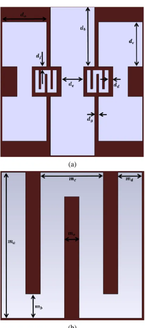
Fig. 2. (a) Whole isolating structures; (b) M Shape isolating structure.
The isolating structure is composed of three dumb bells with two M shaped structures. The central dumb bell is surrounded by M shaped structures followed by smaller dumb bells. The distance between all dumb bells is kept 2.5mm and in that distance M shape is introduced. Both isolating structures are shown in Fig. 2(a) and (b) respectively. The edge to edge distance is kept 20mm and center to center is kept 34.5mm. A 1.9mm whole is also made in ground plane to connect SMA connector inner probe to the patches.
The matching impedance is set to be 50ohm. The overall dimensions of dumb bell and M shaped isolating unit are given in Tables I and II.
TABLE I. DIMENSIONS OF DUMB BELL STRUCTURE Parameters da db dc dd de df dg
Value (mm) 6 8 6 0.025 3 0.025 0.025 TABLE II. DIMENSIONSOFMSTRUCTURE
Parameters ma mb mc md me
Value (mm) 3 0.5 1.2 0.5 0.2
ma, mb, mc, md, me are the dimensions of M shape
isolating structure, whereas da, dc are the dimensions of central dumbbell while db, de are the dimensions of side dumbbells respectively. df, dd, dg are the separating distance among isolating elements. Patterns are introduced in efforts to change the electromagnetic conduction properties of structures. These structures relative to size of wavelength acts usually as block filers for certain number of frequencies and can be considered as LC network. Surface wave’s interference reduction was seen with insertion of isolating structure.
III. RESULTS AND DISCUSSION
The proposed structure as stated was designed in Computer Simulation Technology 2014 version. Performance parameters like return loss, gain, directivity, bandwidth, and VSWR, E and H fields are discussed with and without isolating structure. The detail results comparison are shown in Table III.
TABLE III. PERFORMANCEPARAMETERS
Parameters Conventional Proposed
Return Loss,S11 -30.25dB -28.0dB Coupling, S22 -18.00dB -42.05dB Gain 5.18dB 4.82dB Directivity 6.15dBi 6.8dBi VSWR 1.05 1.25 Bandwidth 180MHz 200MHz
The return loss plot or reflection coefficient was slightly decreased in proposed antenna with gain but overall directivity patterns have increased. The return loss of both designs is shown in Fig. 3(a) and isolation enhancement with and without proposed defected ground structure is shown in Fig. 3(b). Isolation enhancement is taken in terms of S12 as only one of the patch elements has been excited. It is clearly visible that up to -28dB of isolation is increased summing up to -42dB which is clearly much more them [14], [15].
(IJACSA)International Journal of Advanced Computer Science and Applications Vol. 9, No.4, 2018 25 | P a g e www.ijacsa.thesai.org (a) (b)
Fig. 3. S parameters of conventional and proposed antenna.
The proposed antenna has shown good bandwidth results with addition of 20MHz. Also antenna has shown satisfactory results and has shown minimum miss match losses.
Fig. 4. E field pattern.
Fig. 5. H field pattern.
The standardized Gain pattern in E and H planes of conventional and proposed structures is shown in Fig. 4 and 5 respectively. The H plane patterns have been tilted a little bit because of the proposed structure and so the direction of current of excited patch is perpendicular to the passive patch.
From figures it is cleared that existence of DGS have not altered radiation patterns. Only the patterns are marginally propped since as of asymmetry in the plane from which it is evident that not only proposed structure successfully blocked the surface waves but also mends the patterns.
Fig. 6. 3D view of far field.
Fig. 6 shows the 3D directivity view of proposed antenna. The proposed antenna shows high directivity results of 6.8dBi with main lobe direction of 16 degrees.
(IJACSA)International Journal of Advanced Computer Science and Applications Vol. 9, No.4, 2018
26 | P a g e www.ijacsa.thesai.org
IV. CONCLUSION
A fresh DGS design is presented in this study to improve isolation enhancement between MIMO antennas. A very simple structure is designed comprising of two shapes M and Dumb bells using Computer simulation technology software. By insertion of proposed patterns reduction of mutual coupling was achieved up to more than 20dB and was reduced to sum of -42dB also improving 20MHz of bandwidth. The antenna showed good performance parameters results such as gain, directivity, miss match losses with minor alteration in radiation patterns. The isolated embedded structure antenna can be used for satellite services and for radio altimeter applications.
V. FUTURE WORK
The proposed antenna work in future can be extended for circular polarized antennas that are suitable for avionics, aerospace and satellite applications. Also this work can be extended to enhance isolation among MIMO elements by increasing DGS elements.
REFERENCES
[1] Mekala, C., Saranya, P., & Narayanan, V. S. (2014). Survey on Mutual Coupling Reduction Techniques for Imaging Radar Application. i-Manager's Journal on Communication Engineering and Systems, 3(3), 28.
[2] Soltani, Saber, and Ross D. Murch. "Designing planar MIMO antennas using a novel canonical dual port antenna." Antennas and Propagation
Society International Symposium (APSURSI), 2014 IEEE. IEEE, 2014.
[3] Altaf, Ahsan, M. A. Alsunaidi, and Ercument Arvas. "A novel EBG structure to improve isolation in MIMO antenna." USNC-URSI Radio
Science Meeting (Joint with AP-S Symposium), 2017. IEEE, 2017.
[4] S. D. Assimonis, T. V. Yioultsis, C. S. Antonopoulos, "Design and Optimization of Uniplanar EBG Structures for Low Profile Antenna Applications and Mutual Coupling Reduction", Antennas and Propagation IEEE Transactions on, vol. 60, pp. 4944-4949, 2012 [5] Peng, L., Sun, K., Xie, J. Y., Qiu, Y. J., & Jiang, X. (2016, October).
Coupling reduction of closely packed antennas by stringing EBG structure. In Antennas, Propagation and EM Theory (ISAPE), 2016 11th
International Symposium on (pp. 716-719). IEEE.
[6] Saad Hassan Kiani, Shahryar Shafique Qureshi, Khalid Mahmood, Mehr-e- Munir and Sajid Nawaz Khan, “Tri-Band Fractal Patch Antenna for GSM and Satellite Communication Systems” International Journal of Advanced Computer Science and Applications(IJACSA), 7(10), 2016. [7] Karthik, R., Manjunath, R. K., & Kumaraswamy, H. V. (2015).
Rectangular slotted ground structure to reduce Mutual coupling in Microstrip Patch antenna array. International Journal of Advanced Research in Electronics and communication Engineering (IJARECE), 4(5).
[8] Altaf, Ahsan, M. A. Alsunaidi, and Ercument Arvas. "A novel EBG structure to improve isolation in MIMO antenna." USNC-URSI Radio Science Meeting (Joint with AP-S Symposium), 2017. IEEE, 2017. [9] Ahmed, M. I., Sebak, A., Abdallah, E. A., & Elhennawy, H. (2012,
June). Mutual coupling reduction using defected ground structure (DGS) for array applications. In Antenna Technology and Applied Electromagnetics (ANTEM), 2012 15th International Symposium on (pp. 1-5). IEEE.
[10] Li, Q., Feresidis, A. P., Mavridou, M., & Hall, P. S. (2015). Miniaturized double-layer EBG structures for broadband mutual coupling reduction between UWB monopoles. IEEE Transactions on Antennas and Propagation, 63(3), 1168-1171.
[11] Zulkifli, F. Y., Rahardjo, E. T., & Hartanto, D. (2010). Mutual coupling reduction using dumbbell defected ground structure for multiband microstrip antenna array. Progress In Electromagnetics Research Letters, 13, 29-40.
[12] Kiani, Saad Hassan, Khalid Mahmood, Umar Farooq Khattak, Burhan-Ud-Din, and Mehre Munir. "U Patch Antenna using Variable Substrates for Wireless Communication Systems." International Journal of Advanced Computer Science and Applications 7, no. 12 (2016): 286-291.
[13] Balanis, Constantine A. Antenna theory: analysis and design. John Wiley & Sons, 2016.
[14] Tu, D. T. T., Van Hoc, N., Quan, H., & Van Yem, V. (2016, July). Compact MIMO antenna with low mutual coupling using defected ground structure. In Communications and Electronics (ICCE), 2016 IEEE Sixth International Conference on (pp. 242-247). IEEE.
[15] Veeramani. A, Afsane Saee Arezomand, Vijayakrishnan. J, Ferdows B. Zarrabi, “Compact S-shaped EBG Structures for Reduction of Mutual Coupling,” 2015 Fifth International Conference on Advanced Computing & Communication Technologies, 2015.