Bir Ölçüm Cihazının Programlama Arayüzü için Model
Öğrenme
Atakan Garipler1, Ege Sorguç1, Evrim Özel1, Salih Emre Uslu1, Mahdi Saeedi Ni-koo1,2, and Halit Oğuztüzün1
1
Orta Doğu Teknik Üniversitesi, Bilgisayar Mühendisliği Bölümü, Ankara, Türkiye {atakan.garipler, sorguc.ege, evrim.ozel, e174168}@metu.edu.tr
Spark Kalibrasyon Hizmetleri, Ankara, Türkiye [email protected]
Özet. Programlanabilir ölçüm cihazlarının kalibrasyonu için geliştirilen be-tikler, ancak hedef cihaz üzerinde çalıştırılarak test edilebilemekte ve hataların-dan arındırılabilmektedir. Ancak cihazlar çok pahalı ve hazır bulunması zor olabilir. Çözüm için sunduğumuz EmulateIt, Angluin’in L* algoritması’nı temel alan, IEEE 488.2 uyumlu programlanabilir ölçüm cihazları üzerinde çalışan bir model öğrenme ve taklit etme sistemidir. EmulateIt, elektronik bir ölçüm cihazının test arayüzünü algoritmik olarak öğrenir. Öğrenilen model bir sonlu durumlu makina, özelde bir Mealy makinası şeklini alır. Makina, cihaz arayüzünün taklit edilmesini sağlar. Böylece kalibrasyon mühendisleri, kalibra-syon betiklerinin ilk testlerini cihaz mevcut olmadan yapabilirler. EmulateIt kullanıcılara cihazda hatalara neden olan patikaları ve durumları görmelerine ve betiklerini uygun şekilde hatadan arındırmalarına yardımcı olacak bir grafik kullanıcı arayüzü (GUI) sunar. Durum uzayını izlenebilir kılmak için komut parametre değerleri basitleştirilmiştir. Bu nedenle, betik testlerinin son aşamasında gerçek cihazın hazır bulunması ihtiyacı devam edecektir.
Anahtar Kelimeler: Kalibrasyon, Angluin’in L* Algoritması, Sonlu Durum Makineleri, Model Öğrenme, Aktif Öğrenme, IEEE 488.2
Model Learning for the Programming Interface of a
Measurement Device
Atakan Garipler1, Ege Sorguç1, Evrim Özel1, Salih Emre Uslu1, Mahdi Saeedi Ni-koo1,2, and Halit Oğuztüzün1
1
Middle East Technical University, Department of Computer Engineering, Ankara, Türkiye {atakan.garipler, sorguc.ege, evrim.ozel, e174168}@metu.edu.tr
Spark Calibration Services, Ankara, Türkiye [email protected]
Abstract. Calibration scripts for programmable measurement devices can be tested and debugged with target device being available. However, such devices can be quite expensive, thus, their availability can be problematic. We present EmulateIt, a model learning tool that algorithmically learns the command inter-face of an IEEE 488.2 compliant device and makes it available for test script development. EmulateIt implements Angluin’s L* algorithm to build a model of the device interface. The learned model takes the form of a finite state machine, specifically, a Mealy machine. The machine provides the emulation of the de-vice interface. Thus, calibration engineers can perform early testing of their cal-ibration scripts in the absence of the actual device. EmulateIt has a graphical user interface so that engineers can see the paths and states that cause errors on the device and debug their scripts accordingly. To keep the state space tractable, actual command parameter values are simplified. Therefore, the actual device would still be needed in the final phase of testing the scripts.
Keywords: Calibration, Angluin’s L* Algorithm, Finite State Machines, Model Learning, Active Learning, IEE 488.2
1
Introduction
In our era, calibration of programmable measuring devices are conducted by means of calibration software. Calibration engineers create command scripts and data files that should be given as input to the calibration software, which executes them on the de-vice that will be calibrated. Execution of command sequences lead to different states of the device under calibration which are examined during the calibration procedure. Using SCPI (Standard Commands for Programmable Instruments) [1], a standard command language, calibration engineers are able to write test scripts for calibration procedures. Although determining SCPI commands related to concerned procedure (i.e. writing command scripts) is straightforward, writing data files, which determine adjustments (states) of the device that are to be tested, can be difficult for calibration engineers, since there are obscure dependencies between argument values of com-mands due to physical (electronic) restrictions of devices. That is, a data(argument) pair can and probably will prohibit some other command-data(argument) pairs and violations of such prohibitions make the device enter into an error state. From the perspective of the technical specification of the device, such prohibitions can be thought of as the means of avoiding harmful states. Since there is an excessive amount of possible states, keeping track of such dependencies by analy-ing the manual of the device is burdensome. Therefore, calibration engineers may not be able to create correct calibration scripts at first try, hence, they have to debug the files they have created. The only way of debugging these files is trying them on the associated device. However, calibration laboratories do not have all kinds of pro-grammable measuring devices available at all times. Therefore, most of the time, calibration engineers either have to go to the place where the device subject to cali-bration is present and debug their files there, or they have to wait for device to be available. That requirement causes time and money losses, and results in unfavorable working conditions for calibration engineers.
EmulateIt offers a solution to this problem by algorithmically learning the com-mand interfaces of devices in order to create a software model which can play the role of the actual device interface in the debugging phase. Using Angluin’s L* algorithm [2], which is a deterministic active learning [3] algorithm, the Model Learner compo-nent examines the input/output behavior of the actual device iteratively to construct a Mealy Machine [4] model (of the test interfaces) of the device. By trying to depend on the least amount of information/experiments about/on the device,the Learner part of the algorithm produces and conjectures a Mealy Machine that is indistinguishable from the system under learning (from the device in this context). Once a conjecture is produced, the Teacher part of the algorithm tests its correctness. When the correct conjecture is found (i.e. the conjecture is indistinguishable from the system under learning), the L* algorithm returns the Mealy Machine corresponding to the system under learning (i.e. the measurement device), which can then be used by calibration engineers to play the role of the actual device during the testing and debugging of calibration scripts. This solves the problem of cost and space shortages and enables engineers to easily and efficiently debug calibration scripts from their office in the early phases of testing where the command sequences are important. The later phases
of testing, where the actual measured values are important, still need the actual de-vice.
2
High Level System View
EmulateIt has two modes of operation: Learning mode and Emulation mode. The learning mode is the mode of operation in which the test interfaces of devices are modeled in order to be emulated later. Once a device is modeled, the resulting model can be used many times in emulation mode. Using the EmulateIt in emulation mode, calibration engineers are able to replace the actual device by its Mealy Machine mod-el while debugging their calibration scripts.
2.1 High Level View for the Learning Mode
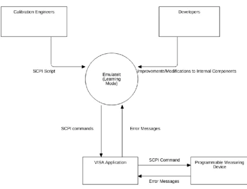
In learning mode, EmulateIt interacts with the PyVISA1 Application , which is Python wrapper for VISA2 shared libraries (Virtual Instrument Software Architecture), by sending SCPI commands and receiving error messages, which will be explained in the architecture section. The PyVISA Application transmits the SCPI commands to the programmable measuring device. It then reads error messages from the output buffer of the device and sends them back to the internal components of EmulateIt. The role of calibration engineers in the learning mode is to provide the SCPI Script input, which determines the test interface to be modeled, into EmulateIt. Finally, developers are able to make improvements or modifications to internal components during its life-time.
2.2 High Level View for the Emulation Mode
The main users of EmulateIt are calibration engineers who need the Device Emulator component (which performs the task of running the Mealy Machine models of devic-es) in order to emulate actual device while debugging the calibration scripts. They give related SCPI scripts and data files to the Device Emulator and receive error mes-sages if their inputs yield an error state. That interaction occurs in a manner similar to the interaction between calibration engineers and calibration software (Calibration software can only be used as a means of executing commands on the device in the presence of the actual device.).
___________________________________________
1
https://pyvisa.readthedocs.io/en/latest/ 2
Fig. 1. Context Diagram for the Learning Mode
3
Architecture
The component diagram of the whole system can be seen in Figure 3. The grey col-ored components are external components, which are the device that will be modeled and the PyVISA, which is the Python package that enables interaction with program-mable measuring devices. The main components of the EmulateIt system are the Model Learner, which fundamentally is the implementation of L* algorithm that cre-ates a Mealy Machine model of the device under learning (DUL) by actively doing experiments on it, and the Device Emulator, which is the component to replace the actual device during the debugging phase of calibration scripts. Device Communica-tor is another component of particular importance due to its role of enabling the Mod-el Learner to functionally and efficiently interact with the device under learning
(DUL). Understandably, the Model Learner is the core component of the learning
mode and the Device Emulator is the core (and the only) component which is active in the emulation mode. Moreover, all other components are responsible for tasks car-ried out in the learning mode. The rest of this section is devoted to detailed explana-tions of the components of the system.
3.1 Model Learner
The Model Learner consists of Teacher and Learner sub-components which corre-spond to the two parts (with names identical to those modules) of L* algorithm. Teacher and Learner work in conjunction to produce a Mealy Machine table that rep-resents the DUL.
First of all, the L* algorithm has to know the input alphabet symbols of the Mealy Machine (device) under learning. In our design, those input alphabet symbols corre-spond to concatenations of commands with their possible argument values. Assuming a test interface with n commands each of which can take k argument values is subject to learning, each command is concatenated with k different argument values in order to create alphabet symbols which results in a total of n·k alphabet symbols. To illus-trate, assume the (fictional) test interface under learning is constituted of two com-mands: SOUR:FUNC:SHAP, which sets the waveform of the device and OUTP:LOAD, which adjusts the output load of the device. Assuming the former command can take 3 different argument values: SIN, SQU, TRI (i.e. the device has 3 waveform options) and the latter command can take 2 argument values: 50Ω and 100Ω (i.e. the device has 2 output load options); it can be concluded that the Mealy Machine model of that test interface will have 5 input alphabet symbols: SOUR:FUNC:SHAP SIN, SOUR:FUNC:SHAP SQU, SOUR:FUNC:SHAP TRI and OUTP:LOAD 50, OUTP:LOAD 100. Likewise, error messages (including “No error” message) are considered as output symbols of the Mealy Machine under learning.
Learner interacts with Teacher, which act as the connection between Learner and the operation of the DUL, by sending two types of queries: membership queries and equivalence queries. Membership queries can be thought as experiments done by Learner on the device. They are simply input sequences (of alphabet symbols) which Learner sends, expecting to receive the respective output sequences. Teacher plugs the input sequence into the DUL (into the programmable measuring device in this context, using the Device Communicator) and gets the output (again using the Device Communicator), to send it back to Learner. In fact, for the sake of simplicity Learner can be thought as if it directly sends membership queries to the DUL (and gets out-puts directly from the device), bypassing Teacher.
As stated in previous sections of this paper, the L* algorithm maintains an iterative approach in order to infer the DUL. It simply conjectures Mealy Machines (the Learner part) and examines their correctness (the Teacher part). At the very beginning of the execution, Learner assumes a Mealy Machine with only one state and it sends an equivalence query to Teacher. That is, it asks to Teacher whether the assumed (conjectured) Mealy Machine is indistinguishable from the DUL. If Teacher estab-lishes that the two are the same, then it sends back “yes” as output, which means the learning process is completed. If not, Teacher gives a counterexample, which is an input sequence that produces different outputs on the two Mealy Machines (the real one and the one learned until that time). The counterexample is processed (in simple terms, added to the Mealy Machine table which represents the model learned until that point of execution) by Learner and the Mealy Machine structure is recreated by depending on the minimum amount of membership queries, which means
conjectur-ing a new Mealy Machine with more states. The active learnconjectur-ing process continues until the DUL (i.e. the test interface of the DUL) is correctly learned.
In order to reply to equivalence queries Teacher creates a set of test sequences, which are (or assumed to be) sufficient to test the correctness of any conjecture. Teacher inputs each test string on both the conjecture and the DUL and compares their outputs. If the outputs given by two machines are different, the corresponding test (input) string is returned to Learner as a counterexample. On the other hand, if none of the test strings produce different outputs on the two machines, Teacher re-turns “yes” to Learner and the algorithm halts by outputting the learned Mealy Ma-chine.
To sum up, using the two mentioned query types and maintaining an iterative ap-proach, the L* algorithm (the Model Learner) is able to successfully construct the Mealy Machine model of the DUL.
3.2 Device Communicator
In learning mode, the Device Communicator establishes the communication between the DUL and the Model Learner. This communication is crucial during the execution of the L* algorithm, since the algorithm needs to send different types of queries (i.e. input sequences) to the device and receive related outputs in order to learn the device. Particularly, it is the component which communicates with the external PyVISA Ap-plication in order to send command sequences produced by the Model Learner to the DUL (in the form of SCPI commands), read error messages from the DUL and then transmit them to the Model Learner, during the learning process.
The other responsibility of the Device Communicator is creating alphabet symbols which will be inputted to the L* algorithm (i.e. to the Model Learner). For that pur-pose, the Device Communicator includes the dictionary of all SCPI commands and their all argument values. At the very beginning, immediately after receiving the SCPI script which determines the test interface under learning, the Device Communicator matches commands in the given script with the commands in the command diction-ary. Moreover, it serves as a pre-processor by detecting unmatched (mistyped etc.) commands. If all commands in the given script are matched with commands in the command dictionary, they are concatenated with each of their possible argument val-ues, thus input alphabet symbols are generated. Generated alphabet symbols are in-putted to the Model Learner in order to enable the learning process to be started.
3.3 Parser
The parser acts as the step between the L* algorithm (the Model Learner) and the Device Emulator. The Parser takes the Mealy Machine table that represents the device as input from the L* algorithm, and parses that table to extract the important infor-mation (states and transitions) about the DUL, specifically the transition relation of the learned Mealy Machine. Once the table is parsed, information of states and transi-tions (i.e. the transition relation) is saved as a file which is reachable by the Device Emulator.
3.4 Device Emulator
The Device Emulator is the component with which users (i.e. calibration engineers) interact mostly. It can reach files on which transition relations of the Mealy Machine models of devices are stored and executes them when requested. Once a device is modeled, it can be emulated many times during the life-time of the EmulateIt soft-ware. By means of a simple GUI, by giving SCPI scripts and data files as input, cali-bration engineers can use the Device Emulator instead of the actual device for debug-ging their calibration scripts. After taking both files as input, the Device Emulator links data combinations in the data file to the commands in the SCPI script line-by-line and applies the resulting command-argument sequences to the Mealy Machine model of the related device. Then, in case of errors, it reports the error-causing se-quences. Moreover, it is able to display the visual representations of the learned Mealy Machine models in order to enable the calibration engineers to see the path yielding the error state in the presence of errors.
4
An Example Run
Suppose a calibration engineer has to write calibration scripts for a device, say it is a Type_X device. Suppose now that there is no Type_X device in her laboratory, and she is not able to physically access a Type_X device on which she can test the scripts she has written. However, she has EmulateIt and had previously made it learn a Type_X device. Thus, she can use EmulateIt in emulation mode instead of a real Type_X device in order to test and debug her scripts. Before describing how she will use EmulateIt in emulation mode, let us illustrate how the device had formerly been modeled using EmulateIt in learning mode.
4.1 Learning Mode
To start, by means of GPIB [1] (General Purpose Interface Bus) the device should be connected to the computer on which EmulateIt is installed. Then, EmulateIt should be started in learning mode. On the Learning Mode screen of the GUI, which is shown in Figure 4, the user (e.g the calibration engineer) should arbitrarily entitle the device and the test interface that will be started to be learned in order to be able to access them in the emulation mode. Afterwards, the SCPI Script, which includes commands used in the concerned calibration procedure, is needed to be provided as input in order to identify the test interface. Finally, the user can initiate the learning process by clicking the “Continue” button. When learning process finishes, an information screen notifies the user and the learned model is saved on a file to be used later in the emula-tion mode. This process can be repeated for each of test interfaces of a device.
Fig. 4. EmulateIt GUI (Learning Mode on the left, Emulation Mode on the right)
4.2 Emulation Mode
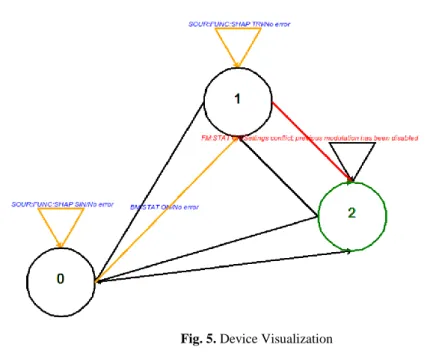
Firstly, user should select Device and Test which refer to devices and tests that are learned before by names given in learning mode by the user. After that selection, the user has two options: Executing the SCPI script and data file on the model of the test interface of the device in the way they are executed on the real device or traversing the Mealy Machine model command by command. When the former option is select-ed, in case of error, error-causing input sequences are identified and printed on the screen. On the other hand, the latter option draws the visual representation of the Mealy Machine model of the concerned test interface to the screen and visualizes state transitions caused by each entered command. Transitions (commands) resulting in an error are colored red and the path ending with error-causing transitions are col-ored orange so as to facilitate identification of error-causing dependencies between commands. Thus, this option can be used to simplify the debugging process, especial-ly after the error-causing input sequence has been found.
Fig. 5. Device Visualization
5
Discussion
EmulateIt has been tested on Agilent 33120A, its 5 test interfaces, the simplest one of which is constituted of 5 commands and the most complex one of which is constituted of 9 commands, have been learned. Learning durations for these interfaces are meas-ured as being between 56 minutes and 31 hours 43 minutes, which are found to be acceptable.
Although each command-argument value pair has to be an alphabet symbol in or-der to produce the most precise model as stated in previous sections, commands that can take an excessive amount of different sequential argument values (e.g. SOUR:VOLT, which sets voltage) are not matched with all of their argument values to create alphabet symbols, in order to keep the state space tractable. Instead, margins of their ranges (i.e. min and max values) and a few intermediate values are used. Thus, for those commands, ranges in which errors occur are able to be determined by the Model Learner. Moreover, using ranges instead of exact values does not signifi-cantly alter the resulting Mealy Machine structure. The reason for that is, the resulting machine becomes different only if at least two different values in predetermined rang-es cause different errors when applied to at least one of the statrang-es of the target device and determining reasonable intermediate values greatly reduces the probability of such occurences. Hence, in spite of possible precision loss due to this method, Emu-lateIt is capable of building highly precise models. Nevertheless, selecting effective intermediate values may not be sufficient in some cases and the real device may be required at the last stage of debugging, in order to remove hard-to-identify bugs.
6
Conclusion
We have shown that a combination of the L* learning algorithm, PyVISA, and some utility modules that transform the data representation (the Parser etc.) is sufficient to construct a Device Emulator, which solves the problem that was initially originated from the need to have physical access to the device. By constructing finite state ma-chine models of test interfaces of devices, EmulateIt provides calibration engineers a much easier way to debug their calibration scripts. With its simple GUI, even engi-neers that have never seen EmulateIt before can spontaneously use it. Since L* algo-rithm learns finite state machines algoalgo-rithmically and deterministically, the final mod-els of test interfaces are concise and of high precision, which increases the level of reliability presented to its users. As stated in the discussion section, some precision loss due to the requirement of keeping the state space tractable may occur. Therefore, at the last phase of debugging, the real device is still needed. However, after debug-ging them on EmulateIt, remaining bugs on the calibration scripts can be easily and quickly removed by testing the scripts on the real device.
Acknowledgement
This work has been supported by TÜBİTAK TEYDEB under project 7180133.
References
1. IEEE Std. 488.2-1992 – IEEE Standard Codes, Format, Protocols to Use With IEEE Std. 488.1-1987, IEEE Standard Digital Interface for Programmable Instrumentation.
2. Angluin, D.: Learning Regular Sets from Queries and Counterexamples. Information and Computation 75, 87-106 (1987).
3. Vaandrager, F.: Model Learning. Communications of the ACM 60(2), 86-95 (2017).
4. Mealy, G.: A Method for Synthesizing Sequential Circuits. Bell System Technical Journal 34, 1045–1079 (1955).
5. Agilent 33120A Function Generator User’s Guide, Agilent Technologies, CA (2002). 6. Agilent 33120A Function Generator Service Guide, Agilent Technologies, CA (2002). 7. Steffen B., Howar F., Merten M.: Introduction to Active Automata Learning from a
Practi-cal Perspective. In: Bernardo M., Issarny V. (eds) Formal Methods for Eternal Networked Software Systems. SFM 2011. Lecture Notes in Computer Science, vol. 6659, pp. 256-296. Springer, Berlin, Heidelberg (2011).