DESIGN, DEVELOPMENT AND
PERFORMANCE EVALUATION OF A
THREE-AXIS MINIATURE MACHINING
CENTER
a thesis
submitted to the department of mechanical engineering and the graduate school of engineering and science
of bilkent university
in partial fulfillment of the requirements for the degree of
master of science
By
Emrullah Korkmaz
July, 2011
I certify that I have read this thesis and that in my opinion it is fully adequate, in scope and in quality, as a thesis for the degree of Master of Science.
Asst.Prof.Dr. Sinan Filiz(Advisor)
I certify that I have read this thesis and that in my opinion it is fully adequate, in scope and in quality, as a thesis for the degree of Master of Science.
Asst. Prof.Dr. Melih C¸ akmakcı
I certify that I have read this thesis and that in my opinion it is fully adequate, in scope and in quality, as a thesis for the degree of Master of Science.
Asst. Prof.Dr. Yi˘git Karpat
Approved for the Graduate School of Engineering and Science:
Prof. Dr. Levent Onural Director of the Graduate School
ABSTRACT
DESIGN, DEVELOPMENT AND PERFORMANCE
EVALUATION OF A THREE-AXIS MINIATURE
MACHINING CENTER
Emrullah Korkmaz M.S. in Mechanical Engineering Supervisor: Asst.Prof.Dr. Sinan Filiz
July, 2011
There is a growing demand for highly accurate micro-scale parts from various industries including medical, biotechnology, energy, consumer, and aerospace. Mechanical micro-machining which is capable of fabricating three dimensional micro-scale features on a wide range of engineering materials such as metals, polymers, ceramics and composites is a viable micro-manufacturing technique to effectively address this demand. Miniature machine tools (MMTs) are developed and used in mechanical micro-machining since their small size improves the ac-curacy and efficiency of the process. The output quality of the final product manufactured on an MMT depends on choosing the optimum machining param-eters. However, the full potential of micro-machining can not be achieved due to challenges that reduce the repeatability of the process. One of the most sig-nificant challenges in micro-machining is the deterioration of output quality due to the MMT vibrations. This thesis demonstrates the development of a three-axis miniature machine tool, the performance evaluation of its micro-scale milling process, and the characterization of its dynamic behaviour using finite element simulations and experiments.
The MMT is designed and constructed using precision three-axis positioning slides (2 micrometers positioning accuracy, 10 nanometers positioning resolution, 60 mm x 60 mm x 60 mm workspace), miniature ultra-high speed spindles (ce-ramic bearing electrical spindle with maximum 50,000 rpm rotational speed and air bearing air turbine spindle with maximum 160,000 rpm rotational speed), a miniature force dynamometer, and a microscope. Three dimensional finite ele-ment simulations are performed on the developed MMT to obtain the static and dynamic characteristics of the spindle side. A maximum static deflection of 0.256 µm is obtained on the designed base when 20 N forces in three directions are
iv
applied to the center of the spindle. Dynamic finite element analysis predicts the first three natural frequencies as 700 Hz, 828 Hz and 1896 Hz; hence corresponding spindle speeds should be avoided for successful application of micro-machining.
To demonstrate the capability of MMT for manufacturing three dimen-sional (3D) features, micro-milling is proposed as a novel method for fabricating Poly(methyl methacrylate) (PMMA) and poly(lactic-co-glycolic acid) (PLGA) polymer micro-needles. The micro-machinability of PMMA and PLGA polymers is investigated experimentally by machining a group of 3 mm length and 100 µm depth slots using 50,000 and 100,000 rpm spindle speeds with different fee-drates (5, 10, 15, and 20 µm/flute). The micro-machinability study concludes that PLGA has better machinability than PMMA. It is also observed that the machining parameters of 50,000 rpm spindle speed and 20 µm/flute feedrate give better output quality. Using these machining parameters, micro needles with different geometries are successfully manufactured from PMMA and PLGA poly-mers. During this study, it is observed that polymer pillars bend due to machining forces and vibrations, which causes dimensional errors.
To address the deterioration of the output quality due to vibrations stemming from machining forces and high-speed-rotations, MMT vibrations particularly fo-cusing on the spindle side dynamics are investigated experimentally using runout (spindle axis offset) measurements and experimental modal analysis techniques. The results are compared with those from three-dimensional finite element simu-lations. The investigation of MMT vibrations indicates that the developed MMT is convenient for accurate applications of micro-machining using air-turbine air bearing spindle. However, the selection of the operation frequencies for electrical spindle is challenging at certain speeds with this design because most of the criti-cal natural frequencies of the developed MMT appear in the operating frequency range of electrical spindle.
Runout measurements using two laser doppler vibrometer (LDV) systems and experimental modal analyis which utilizes an impact hammer and accelerometer are conducted to obtain spindle side dynamics. Runout measurements performed on the miniature ultra-high speed ceramic bearing electrical spindle show that both magnitude and shape of the runout errors vary considerably with spindle speed. A peak of 1.62 µm synchronous runout is observed at 15,000 rpm. Asyn-chronous runout errors become significant between spindle speeds of 40,000 and
v
50,000 rpm and reach to a maximum of 0.21 µm at 45,000 rpm. On the other hand, experimental modal analysis is conducted to obtain both the steady-state and speed dependent frequency response functions (FRFs) of the mechanical structures. Steady state FRFs indicate that 750 Hz and 850 Hz are two im-portant natural frequencies for successful application of micro-machining. Com-pared to the three dimensional finite element simulations, there is 7 % difference for the first mode and 3 % difference for the second mode. Both steady-state experimental modal analysis and finite element simulations could not consider the speed-dependent dynamics. Therefore, experimental modal analysis at differ-ent spindle speeds is also performed and it is concluded that natural frequencies of the mechanical structures change significantly depending on spindle speed. Speed-dependent FRFs show that the maximum response of about 0.35 µm/N is obtained while the spindle is rotating at 16,000 rpm but the peak occurs at 24,000 rpm (400 Hz). In addition, the vibration amplitude grows between the spindle speed of 40,000 rpm and 50,000 rpm.
Experiments and finite element simulations provide a machine operation fre-quency selection guide. It is suggested to avoid two different spindle speed ranges (15,000- 25,000 rpm and 40,000-50,000 rpm) to prevent vibration related inaccu-racies. In addition, structural modifications can be achieved to further optimize the design based on the experimental data obtained in this work. The obtained experimental data can be used to derive mathematical model of the MMT and to perform stability studies to increase the productivity of the micro-machining processes.
Overall, the novel micro-machining technique tested on the developed MMT highlights the quality and ranges that can be achieved in micro-manufacturing.
Keywords: mechanical machining, experimental modal analysis, micro-machinability, miniature machine tools, finite element method, structural dy-namics.
¨
OZET
3-EKSENL˙I M˙INYAT ¨
UR ˙IS
¸LEME MERKEZ˙IN˙IN
TASARIMI, GEL˙IS
¸T˙IR˙ILMES˙I VE PERFORMANSININ
DE ˘
GERLEND˙IR˙ILMES˙I
Emrullah Korkmaz
Makine M¨uhendisli˘gi, Y¨uksek Lisans Tez Y¨oneticisi: Asst.Prof.Dr. Sinan Filiz.
Temmuz, 2011
Medikal, biyoteknoloji, enerji, t¨uketim ve uzay gibi end¨ustrilerden y¨uksek do˘grulukta minyat¨ur par¸calara olan talep artmaktadır. Metal, polimer, seramik ve kompozit gibi malzemelerin ¨uzerine ¨u¸c boyutlu geometrileri i¸sleyebilme ¨
ozelli˘gine sahip mekanik mikro-i¸sleme y¨ontemi mikro-i¸sleme i¸cin olduk¸ca uy-gun bir y¨ontemdir. Minyat¨ur takım tezgahları prosesin do˘grulu˘gunu ve verimlili˘gini arttırdıkları i¸cin geli¸stirilmekte ve mekanik mikro-i¸slemede kul-lanılmaktadırlar. Minyat¨ur takım tezgahlarında ¨uretilen ¨ur¨un¨un kalitesi en iyi kesme ¸sartlarının se¸cilmesine ba˘glıdır. Fakat, mikro-i¸slemenin sahip oldu˘gu potansiyelin tamamı prosesin tekrarlanabilirli˘gini azaltan bazı problemlerden dolayı kullanılamamaktadır. Bu problemlerin en ¨onemlilerinden bir tanesi elde edilen ¨ur¨un¨un kalitesinin takım tezgahının titre¸simleri y¨uz¨unden d¨u¸smesidir. Bu master tezi 3-eksenli bir minyat¨ur i¸sleme merkezinin geli¸stirilmesini, geli¸stirilen i¸sleme merkezinin mikro-frezeleme performansının de˘gerlendirilmesini ve geli¸stirilen takım tezgahının dinamik davranı¸sının deneyler ve sonlu elemanlar y¨ontemiyle karakterize edilmesini ama¸clamaktadır.
Tez kapsamında takım tezgahı tasarlanır ve 3-eksenli pozisyonlama kızakları, minyat¨ur y¨uksek hızlı motorlar, minyat¨ur kuvvet dinamometresi ve mikroskop kullanılarak yapılır. Tasarlananan minyat¨ur i¸sleme merkezinde motorun bu-lundu˘gu kısmın statik ve dinamik karakteristiklerini elde etmek i¸cin sonlu ele-menlar y¨ontemi ile ¨u¸c boyutlu sim¨ulasyonlar ger¸cekle¸stirilir. Motorun merkezine her ¨u¸c y¨onde 20N kuvvet uygulandı˘gında, tasarlanmı¸s olan mekanik par¸caların ¨
uzerinde maksimum 0,256 µm’lik bir statik deplasman elde edilir. Dinamik sonlu elemanlar analizi mekanik par¸caların ilk ¨u¸c do˘gal frekansını 700 Hz, 828 Hz ve 1.896 Hz olarak tahmin eder; dolayısıyla bu frekanslara kar¸sılık gelen motor hızları
vii
ba¸sarılı bir mikro-i¸sleme i¸cin ka¸cınılmalıdır.
Bu master tezinde geli¸stirilen mikro-i¸sleme tezgahının ¨u¸c boyutlu mikro geometrileri i¸sleyebilme yetene˘gini g¨ostermek amacıyla; mikro-frezeleme, Poly(methyl methacrylate) (PMMA) ve poly(lactic-co-glycolic acid) (PLGA) adlı polimer mikro-i˘gnelerin yapımı i¸cin orjinal bir y¨ontem olarak ¨onerilir. PMMA ve PLGA’in mikro-i¸slenebilirli˘gi, 3 mm boyunda ve 100 µm derinli˘gindeki kanal-ların 50.000 devir/dk ve 100.000 devir/dk d¨onme hızlarında ve farklı ilerleme de˘gerlerinde (5, 10, 15, and 20 µm/kesmeucu) kesilmesiyle incelenir. Mikro-i¸slenebilirli˘gin incelenmesi sonucunda PLGA’in i¸slenebilirli˘ginin daha iyi oldu˘gu g¨ozlemlenir. Ayrıca, 50.000 devir/dk ve 20 µm/kesmeucu kesme parametrelerinin en iyi ¨ur¨un kalitesini verdi˘gi g¨ozlemlenir. Bu parametreler kullanılarak farklı ge-ometrilerdeki i˘gneler PMMA ve PLGA polimerlerinden ba¸sarılı bir ¸sekilde ¨uretilir. Bu ¸calı¸sma esnasında, polimer i˘gnelerin kesme kuvvetleri ve titre¸simden dolayı e˘gildikleri ve bunun da boyutsal hatalara sebep oldu˘gu g¨ozlemlenir.
¨
Ur¨un kalitesinin kesme kuvvetlerinden ve y¨uksek hızla d¨on¨u¸sten kaynaklanan titre¸simden dolayı azalmasını engellemek amacıyla, geli¸stirilmi¸s olan makinenin titre¸simleri ¨ozellikle motorun bulundu˘gu kısma odaklanarak motorun eksenden ka¸cıklı˘gının ¨ol¸c¨ulmesi ve modal analiz ile deneysel olarak incelenir. Elde edilen sonu¸clar sonlu elemanlar y¨ontemiyle yapılan ¨u¸c boyutlu sim¨ulasyonların sonu¸clarıyla kar¸sıla¸stırılır. Bu inceleme g¨ostermektedir ki, geli¸stirilmi¸s olan minyat¨ur i¸sleme merkezi, havalı motorla mikro-i¸sleme i¸cin ba¸sarılı bir ¸sekilde kul-lanılabilir. ¨Ote yandan, bu tasarım ile elektrikli motor kullanıldı˘gı zaman belirli hızlarda ¸calı¸smak olduk¸ca risklidir. C¸ ¨unk¨u tasarımın do˘gal frekanslarının ¸co˘gu elektrikli motorun ¸calı¸sma aralı˘gı i¸cindedir.
Motorun ekseninden ka¸cık d¨onmesinin ¨ol¸c¨ulmesi lazer dopler titre¸sim¨ol¸cerler kullanılarak, deneysel modal analiz de darbe ¸cekici ve ivme¨ol¸cer kullanılarak ger¸cekle¸sitirilerek motorun bulundu˘gu kısmın dinamiklerinin elde edilmesi ama¸clanır. Y¨uksek hızda seramik rulmanlı elektrikli motorun ¨uzerinde yapılan eksenden ka¸cık d¨onme ¨ol¸c¨umleri hem bu ka¸cıklı˘gın ¸seklinin hem de b¨uy¨ukl¨u˘g¨un¨un motorun hızıyla de˘gi¸sti˘gini g¨osterir. Motorun hızıyla senkronize olan eksen ka¸cıklı˘gının 15.000 devir/dk d¨onme hızında maksimum de˘ger olan 1,65 µm’ye ula¸stı˘gı g¨or¨ul¨ur. Motorun hızıyla senkronize olmayan eksen ka¸cıklı˘gının 40.000 devir/dk ve 50.000 devir/dk d¨onme hızları arasnda ¨onemli oldu˘gu ve 45.000 devir/dk’da maksimum de˘ger olan 0.21 µm’ye ula¸stı˘gı g¨or¨ul¨ur. Ote yandan,¨
viii
mekanik par¸caların durgun halde ve hıza ba˘glı frekans tepki fonksiyonlarını bul-mak amacıyla deneysel modal analiz ger¸cekle¸stirilir. Durgun haldeki frekans tepki fonksiyonları 700 Hz ve 850 Hz’i geli¸stirilen MMT’de iki ¨onemli do˘gal frekans olarak i¸saret eder. Bu sonu¸clar ¨u¸c boyutlu sonlu elemanlar methodu ile yapılan simulasyonlar ile kar¸sıla¸stırıldı˘gında; ilk mod i¸cin % 7, ikinci mod i¸cin % 3 fark oldu˘gu g¨or¨ul¨ur. Hem sonlu elemanlar y¨ontemi hem de durgun haldeki frekans tepki fonksiyonları hıza ba˘glı dinamikleri g¨oz ¨on¨une alamaz. Bu nedenle deneysel modal analiz farklı d¨onme hızlarında da ger¸cekle¸stirilir ve mekanik yapıların di-namiklerinin d¨onme hızıyla de˘gi¸sti˘gi g¨ozlemlenir. D¨onme hızına ba˘glı olan frekans tepki fonksiyonları maksimum 0.35 µm/N bir tepkinin, motor 16.000 devir/dk d¨onme hızında d¨onerken 24.000 devir/dk d¨onme hızına kar¸sılık gelen frekansta oldu˘gunu i¸saret eder. Bunun yanı sıra 40.000 ve 50.000 devir/dk d¨onme hızlarında titre¸simin arttı˘gı g¨or¨ul¨ur.
Deneyler ve sonlu elemanlar y¨ontemiyle ger¸cekle¸stirilen sim¨ulasyonlar geli¸stirilen makine i¸cin bir ¸calı¸sma frekansı se¸cme rehberi sa˘glar. Bu rehbere g¨ore titre¸simle ilgili problemleri engellemek i¸cin iki farklı d¨onme hızı aralı˘gı (15.000-25.000 devir/dk ve 40.000-50.000 devir/dk) sakınılmalıdır. Buna ek olarak, bu tez kapsamında elde edilen deneysel veriler baz alınarak yapısal modifikasyonlar yapılabilir ve tasarım daha da iyile¸stirilebilir. Elde edilen deneysel veriler maki-nenin matematiksel modelini elde etmek i¸cin ve kararlılık limitlerini elde edip verimlili˘gini arttırmak i¸cin de kullanılabilirler.
En genelde, gelitirilmi¸s olan minyat¨ur i¸sleme merkezi ¨uzerinde test edilen mekanik mikro-i¸sleme y¨otemi, mikro-i¸slemede ula¸sılabilecek kalite ve aralı˘gı or-taya koyar.
Anahtar s¨ozc¨ukler : mekanik i¸sleme, deneysel modal analiz, mikro-i¸slenebilirlik, minyat¨ur i¸sleme merkezleri, sonlu elemenlar methodu, yapı di-nami˘gi.
Acknowledgement
I would like to express my sincere gratitude to my advisor, Asst.Prof.Sinan Filiz, for his encouragement, guidance and support throughout my thesis work. His perpetual energy as an advisor and enthusiasm in research had motivated me and made the research life smooth and rewarding for me.
I also owe special thanks to Prof.Dr. Adnan Akay, Asst.Prof. Melih C¸ akmakcı, Asst. Prof. Yi˘git Karpat, Asst Prof. Ilker Temizer and Dr. Erdrin Azemi for their valuable contributions to my thesis.
Special thanks go also to my officemates for their support in my work. They made the M.S. experience memorable for me.
Thanks to my sponsors. This work was financially supported by the Scien-tific and Technological Research Council of Turkey (T¨ubitak) 1001 grant (MAG 109M530), the State Planning Agency (DPT) of Turkey funding and the Euro-pean Union Marie Curie FP7 reintegration grant (FP7-PEOPLE-2010-RG No: 268456-IMMP).
I wish to thank the Institute of Materials Science and Nanotechnology (UNAM/Turkey) for the measurement and characterization studies.
Last but not least, I would like to thank to my family and friends, for their love and encouragement.
Contents
1 Introduction 1
1.1 Mechanical micro-machining . . . 4
1.2 Challenges of mechanical micro-machining . . . 5
1.3 Motivation . . . 7
1.4 Objective . . . 9
2 Background Information and Literature 10 2.1 Development and performance evaluation of miniature machine tools 10 2.2 Dynamics of conventional machine tools . . . 12
2.3 Dynamics of miniature machine tools . . . 13
3 Design and Construction of MMT 15 3.1 Subsystems of the Miniature Machine Tool . . . 16
3.1.1 High-precision positioning subsystem . . . 16
3.1.2 Motion control subsystem . . . 17
3.1.3 Miniature ultra-high-speed (UHS) spindle subsystem . . . 18 x
CONTENTS xi
3.1.4 Process monitoring subsystem . . . 28
3.2 Machine Integration . . . 29
3.2.1 Design of the mechanical parts . . . 29
3.2.2 Computer Aided Drawing Model of Miniature Machine Tool 37 3.2.3 Integration of major subsystems and precision alignment . 38 4 Performance Evaluation of MMT 41 4.1 An experimental investigation of micro-machinability of PMMA and PLGA polymers . . . 42
4.1.1 Study of micro-machining parameters . . . 42
4.1.2 Repeatability Analysis . . . 45
4.2 Fabrication of PMMA AND PLGA micro needles . . . 46
5 Investigation of MMT Dynamics 49 5.1 Runout characteristics of ultra-high speed miniature spindles for micromachining . . . 50
5.1.1 Experimental Set-up . . . 51
5.1.2 Alignment of the lasers . . . 54
5.1.3 Runout measurements . . . 60
5.2 Experimental Modal Analysis . . . 67
5.2.1 Experimental Set-up . . . 68
CONTENTS xii
5.2.3 Natural Frequencies (Experimental and Numerical) . . . . 72 5.2.4 Speed Dependent FRFs . . . 75
6 Summary and Conclusions 78
7 Future work 81
A Fpga Technology 93
A.1 Virtual Data Acquisition Card . . . 93 A.2 Analog Input and Output Host.VIs . . . 95
B Labview Environment for Experiments 96
C Runout Measurement Results 100
List of Figures
1.1 Applications and market share of micro systems [5] . . . 2
1.2 Examples of Miniature Machine Tools (a) 2nd Generation UIUC MMT [84] (b) Recently developed MMT in USA [46] . . . 4
1.3 Structural loops of a miniature machine tool . . . 8
2.1 Dynamics of milling (a) Multiple-DOF cutting tool dynamic mod-els in reference [7] (b) Distributed parameter model of the cutting tool in reference [89] . . . 13
3.1 (a) The ultra-precision miniature machine tool, (b) the zoomed in machining area . . . 16
3.2 General block diagram for speed control . . . 19
3.3 Analog option of the Tachometer . . . 20
3.4 Spindle Speed-Voltage Relationship . . . 20
3.5 Block diagram for acquiring spindle speed . . . 21
3.6 (a) Signal Amplifier (b) Signal Amplifier Connections . . . 22
3.7 Calibration block diagram . . . 22
LIST OF FIGURES xiv
3.8 PID control block diagram created in SIMULINK . . . 24
3.9 Step Response for the desired spindle speed of 50,000 rpm . . . . 24
3.10 Step Response for the desired spindle speed of 100,000 rpm . . . . 25
3.11 PID control block Diagram created in LABVIEW . . . 26
3.12 Front Panel created in LABVIEW . . . 26
3.13 All configurations for spindle clamp-base structure . . . 31
3.14 Finite element simulation of last configuration with the properties of AISI 304 Stainless Steel . . . 34
3.15 3D CAD models of the designed mechanical parts (a) Spindle base (b) Spindle clamp . . . 34
3.16 Fundamental mode shapes in the operating frequency range (a) First mode shape (699.69 Hz) (b) Second mode shape (827.91 Hz) (b) Third mode shape (1895.8 Hz). . . 36
3.17 3D CAD model of the developed MMT . . . 37
3.18 Perpendicularity of spindle to the stages . . . 39
3.19 Precision alignment surfaces and coordinate system . . . 39
3.20 Alignment in xy plane using precision block . . . 40
4.1 SEM images of burr formation for PMMA slot machined with (a) 50,000 rpm spindle speed and 5 µm/flute feedrate, (b) with 50,000 rpm and 20 µm/flute . . . 43
4.2 PMMA material machined at 100,000 rpm and 10µm/flute. Top channel did not melt while the second machined channel melted during the process. . . 43
LIST OF FIGURES xv
4.3 Average surface roughness values for PMMA and PLGA . . . 44 4.4 SEM images of burr formation for PLGA slot machined with (a)
100,000 rpm, 5 µm/flute, and (b) with 50,000 rpm, 20 µm/flute. 44 4.5 Cross section representation of the tool path used to create micro
needles (a) Tool opening a pocket within the polymer substrate, (b) tool creating slots that eventually become pillars, (c-d) tool path to create tapers on the micro pillars, and (e) final product. . 47 4.6 PMMA and PLGA micro needle dimensions: (1) width
(w)=232x216 µm, height (h)=400 µm, (2) w=220x419 µm, h=800 µm, (3) w=419x416 µm, h=800 µm (4) w=415x216 µm, h=400 µm. . . 47 4.7 PLGA micro needle array with three different taper geometries.
Right: Four taper needle with w=200x200 µm, total h=800 µm and taper angle for all sides ∼28o. . . 48
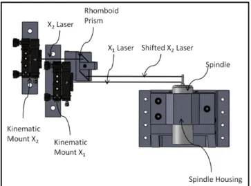
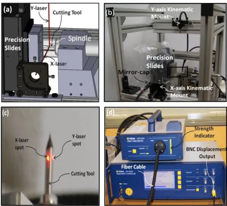
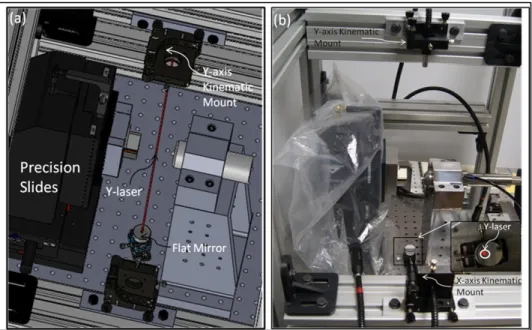
5.1 Experimental facility for runout measurement (a) The measure-ment set-up for vibration measuremeasure-ments (b) A 3D model of the experimental set-up . . . 52 5.2 Staggered laser arrangement with a rhomboid prism to reduce the
laser seperation by laterally shifting the X2 laser for relative
mea-surement . . . 53 5.3 Rough alignment of the lasers on the cutting tool (a) 3D model
of the rough alignment (b) Rough alignment of the lasers on the mMT (c) Zoomed on cutting tool (d) OFV-552 Vibrometer and OFV-5000 Vibrometer Controller. . . 55
LIST OF FIGURES xvi
5.4 Fine alignment of the laser (a) 3D model of the focusing X-laser on the gold coating (b) Focusing X-X-laser on the gold coating on the MMT (c) 3D model of the 900 deflection of the X-laser (d)
Deflection of the X-laser on to the flat mirror placed on a goniometer. 56 5.5 Fine alignment of the Y-laser (a) 3D model of the focusing Y-laser
on the flat mirror placed on a goniometer (b) Focusing Y-laser on
flat mirror on the MMT. . . 57
5.6 Image of the two lasers after alignment . . . 58
5.7 Line fitting on the laser images (a) Black and white image (b) Fitted lines on the pixels . . . 59
5.8 Image processing result for the angle between two lasers . . . 59
5.9 Raw X and Y runouts from the lasers . . . 61
5.10 Data converted to polar coordinates . . . 62
5.11 Steps in frequency domain analysis (a) Centered data in polar co-ordinates (b) Synchronous runout calculated by using spindle har-moncis (c) Asynchronous runout calculated using non-harmonics of rotational speed . . . 63
5.12 Radial runout results for 15,000 rpm . . . 64
5.13 Radial runout results for 30,000 rpm . . . 64
5.14 Radial runout results for 45,000 rpm . . . 64
5.15 Spindle speed average synchronous runout errors relationship . . . 65
5.16 Spindle speed asynchronous runout errors relationship . . . 66
5.17 Cut-off Frequency (a) Impact force time history (b) Frequency spectrum of a typical impact . . . 68
LIST OF FIGURES xvii
5.18 Block Diagram of an FRF (a) Time Domain (b) Frequency Domain 69 5.19 Dataprocessing (a) Impact force time history (b) Acceleration
Time History (c) Impact force frequency domain magnitude (d)
Acceleration frequency domain magnitude . . . 71
5.20 Average frequency response function measurements for 2500 Hz frequency range . . . 73
5.21 Steady state frequency response magnitude in linear scale . . . 74
5.22 Average frequency response function measurements for 5000 Hz frequency range . . . 75
5.23 Typical response while spindle is rotating . . . 76
5.24 Linear frequency response functions for (a) 16,000 rpm (b) 45,000 rpm . . . 76
A.1 Virtual DAQ environment for only analog input . . . 94
A.2 Virtul DAQ environment for both analog input and analog output 94 A.3 Data acquiring Block Diagram . . . 95
A.4 An example of general host.vi for both analog inputs and outputs 95 B.1 Displacement Measurement Block Diagram . . . 97
B.2 Front Panel for Displacement Measurement . . . 97
B.3 Simple Impact Test Block Diagram . . . 98
B.4 Front Panel for Impact Test . . . 98
B.5 Force Measurement Block Diagram . . . 99
LIST OF FIGURES xviii
C.1 Radial runout results for 1,000 rpm . . . 101
C.2 Radial runout results for 2,000 rpm . . . 101
C.3 Radial runout results for 5,000 rpm . . . 101
C.4 Radial runout results for 10,000 rpm . . . 102
C.5 Radial runout results for 15,000 rpm . . . 102
C.6 Radial runout results for 20,000 rpm . . . 102
C.7 Radial runout results for 25,000 rpm . . . 103
C.8 Radial runout results for 30,000 rpm . . . 103
C.9 Radial runout results for 35,000 rpm . . . 103
C.10 Radial runout results for 40,000 rpm . . . 104
C.11 Radial runout results for 45,000 rpm . . . 104
C.12 Radial runout results for 50,000 rpm . . . 104
D.1 Average frequency response function measurements for 2,000 rpm 106 D.2 Average frequency response function measurements for 4,000 rpm 106 D.3 Average frequency response function measurements for 6,000 rpm 107 D.4 Average frequency response function measurements for 8,000 rpm 107 D.5 Average frequency response function measurements for 10,000 rpm 108 D.6 Average frequency response function measurements for 12,000 rpm 108 D.7 Average frequency response function measurements for 14,000 rpm 109 D.8 Average frequency response function measurements for 16,000 rpm 109
LIST OF FIGURES xix
D.9 Average frequency response function measurements for 18,000 rpm 110 D.10 Average frequency response function measurements for 20,000 rpm 110 D.11 Average frequency response function measurements for 22,000 rpm 111 D.12 Average frequency response function measurements for 24,000 rpm 111 D.13 Average frequency response function measurements for 26,000 rpm 112 D.14 Average frequency response function measurements for 28,000 rpm 112 D.15 Average frequency response function measurements for 30,000 rpm 113 D.16 Average frequency response function measurements for 32,000 rpm 113 D.17 Average frequency response function measurements for 34,000 rpm 114 D.18 Average frequency response function measurements for 36,000 rpm 114 D.19 Average frequency response function measurements for 38,000 rpm 115 D.20 Average frequency response function measurements for 40,000 rpm 115 D.21 Average frequency response function measurements for 42,000 rpm 116 D.22 Average frequency response function measurements for 44,000 rpm 116 D.23 Average frequency response function measurements for 45,000 rpm 117 D.24 Average frequency response function measurements for 46,000 rpm 117 D.25 Average frequency response function measurements for 47,000 rpm 118 D.26 Average frequency response function measurements for 48,000 rpm 118 D.27 Average frequency response function measurements for 49,000 rpm 119 D.28 Average frequency response function measurements for 50,000 rpm 119
List of Tables
3.1 Specifications of the slides [1] . . . 17
3.2 Specifications of the air-turbine spindle [2] . . . 18
3.3 Calibration results . . . 23
3.4 Specifications of the electrical spindle [3] . . . 27
3.5 Properties of materials considered in the static analysis . . . 30
3.6 Results of the static analysis . . . 32
3.7 Properties of materials considered in the static analysis . . . 35
4.1 ANOVA results. Surface roughness p values. . . 45
Chapter 1
Introduction
There are several benefits of miniaturization such as reduction in space, mate-rial, and energy requirements and improved efficiency. Highly accurate miniature components with micro-scale features are increasingly in demand for various in-dustries such as medical, biotechnology, consumer, aerospace and energy for using the advantages of micro-scale parts [20, 88, 21, 9, 58].
Miniaturization is very promising for medical and biotechnology applications which require micro-systems for interacting with molecules, proteins, cells and tissues. For instance, with the recently developed micro-/nano-manufactured devices, cancer agent molecules like PSA, CA can be detected at early stages of the cancer. Miniaturizing the cancer detection devices will reduce the cost of cancer monitoring and save many lives [16]. Furthermore, to avoid tissue damage during surgeries, most implants and surgery equipments are required to be miniature [16, 17, 30]. Miniature medical equipments including probes, stents and fiberoptic cameras have been increasingly used in surgeries, and their market is expected to grow rapidly [59].
While miniaturization is a necessity in biotechnology and medical applications such as the ones described above, it is advantageous to use miniature components in other applications. With miniaturization, products with more functionality is
CHAPTER 1. INTRODUCTION 2
achieved. For example, today a cell phone not only provides mobile communica-tion, but also has wireless internet conneccommunica-tion, global positioning service, camera for high quality pictures, audio/video player and video games. Digital data stor-age systems (hard-disc drives) that include miniature mechanical components get smaller and store more data. Researchers are working on developing miniature fuel-cells which will be replaced with batteries in portable devices. Increasing usage of fuel-cells will reduce the negative effects of batteries on environment [86]. Furthermore, with miniaturization, orbiting costs of space satellites can be lowered, satellite life and maneuverability can be increased. Research projects have been recently initiated to develop satellites that weight less than a kilogram [11]. Shortly, miniaturization have been becoming increasingly popular in many applications [20].
Recent reports related to applications and market share of micro-systems have indicated that the demand for micro-devices was expected to double and reach from $12 billion dollars to $25 billion dollars from 2004 to 2009 (see Figure 1.1) [5]. Furthermore, it is predicted that non-invasive surgery equipments consisting micro-scale parts will increase its market from $16 billion dollars in 2009 to $23 billion in 2014 [59].
CHAPTER 1. INTRODUCTION 3
To effectively address the increasing demand in micro-manufacturing, reliable and repeatable micro-component fabrication methods are required [14]. The most commonly used micro-manufacturing technique today is lithography/etching based fabrication where silicon materials are photo-etched through chemical and dry processes, usually in large batch production. Although successful in micro electro mechanical system (MEMS) applications, lithography based methods have geometric and material limitations [57]. The feasibility of other micro-fabrication processes such as focused ion beam machining (FIB), femtosecond laser micro-machining (FLM), selective laser sintering (SLS), and electro-chemical micro-machining (ECM) to manufacture commercially viable micro-components has been investi-gated by many researchers. They concluded that the majority of these methods are slow, and limited to a few silicon-based materials and essentially planar ge-ometries [57, 51, 6]. Since the possibilities of the miniaturization are expanding into three dimensional features fabricated on a variety of engineering materials such as metals and ceramics, the increasing demand in micro-systems cannot be effectively addressed due to limitations in the currently used micro-fabrication techniques.
Recently, processes with less geometric and material limitations increasingly have received more attention to overcome the drawbacks of the aforementioned methods. These processes are mechanical micro-machining, micro-forming, laser micro-machining, laser micro-sintering, micro-electro discharge machining and micro-injection molding. Each micro-manufacturing technique has specific ad-vantages and application area. Having minimal material and geometric limita-tions, and higher productivity, mechanical micro-machining is a quite promising technique for micro-manufacturing [43]. This thesis mainly focuses on mechanical micro-machining.
CHAPTER 1. INTRODUCTION 4
1.1
Mechanical micro-machining
Mechanical micro-machining is one of the viable micro-manufacturing techniques for fabricating micro-scale features and components with three-dimensional com-plex geometries on metals, polymers, ceramics and composites [48, 30, 26, 20, 32, 33]. It is the scaled down version of the traditional metal cutting techniques such as drilling and milling where the material is removed mechanically using micro-scale cutting tools [48, 84, 85, 49]. Although it might be possible to perform mechanical micro-machining on traditional precision machine tools, it is gener-ally performed on miniature-machine-tools (MMTs) to achieve a better control in dimensional and thermal errors, and to reduce the required space, power and cost for operation [75, 22, 63, 83, 90, 47, 8, 40]. Miniature machine tools are equipped with high precision positioning stages, ultra high speed spindles, and measurement devices such as dynamometers and microscopes to monitor the pro-cess [47, 8, 40, 39]. Figure 1.2 shows some examples of miniature machine tools.
Figure 1.2: Examples of Miniature Machine Tools (a) 2nd Generation UIUC MMT [84] (b) Recently developed MMT in USA [46]
During micro-machining, micro-scale cutting tools which are produced from hard materials such as tungsten carbide or diamond, and rotated in the ultra-high speed spindles to attain effective material remove rates are used for mechanically removing the material [48, 30, 26].
CHAPTER 1. INTRODUCTION 5
1.2
Challenges of mechanical micro-machining
However, the full potential of mechanical micro-machining can not be achieved due to the challenges that reduce the repeatability of the process [30, 26, 14]. The challenges include non-ideal micro-cutting tool geometry, uncertainty arising from micro-structure of the workpiece, lack of knowledge in micro-machinability of materials, and vibrations due to periodic machining forces and rotating unbal-ances [30, 14, 37, 36, 46]. These issues have to be investigated and eliminated for successful application of micro-manufacturing.
There is a fundamental limitation of how sharp the cutting tools can be made in micro-scale due to the limitations in the tool manufacturing process (grinding) so, the micro-cutting tools cannot be considered as ideally sharp. The edge radius (sharpness) of the tools in micro-machining are in the order of machining parameters such as feedrate and uncut chip thickness, which makes the cutting edge ”blunt” [30, 61]. Bluntness of the cutting edge makes mechanics of the process complicated. It renders the process ploughing (rather than shearing) dominated, in which a large portion of the material is deformed and pushed under the tool [26, 45].
Blunt edges introduce the phenomenon referred as the minimum chip thickness effect. This phenomenon shows that when the uncut chip thickness is below a certain chip thickness, no chip is produced [48, 72, 34, 26]. Large cutting edge radius also causes large forces, tool wear and breakage, poor surface finish, and extensive burr formation along the edges of the machined feature [45, 26, 53].
Micro-machining experiments in Advanced Microsystem Technologies Labo-ratory of Mechanical Engineering Department at Bilkent University indicated that different materials have different burr formation characteristics. It was also observed that with increasing wear of the cutting-tool, burring increases.
In micro machining, tool wear mechanism is also different and the tool life is reached very abruptly [78, 53]. The tool diameter significantly decreases because of the tool wear, which affects the output quality of the process. Since higher
CHAPTER 1. INTRODUCTION 6
spindle speeds (≥ 20000 rpm) are required to attain effective material removal rates, fatigue failure of the micro-cutting tools by repeated loading and unloading may also become important during micro-machining [26, 10].
Non-homogeneous micro-structure of the workpiece material also plays an im-portant role in micro-machining. In conventional machining, with respect to the uncut chip thickness, the grains are smaller, so the effect of individual grains is averaged and the workpiece material can be assumed as isotropic. However, in micro-scale machining, the size of workpiece micro-structures is of the same order of magnitude as the process geometry. The cutting-tool goes through in-dividual crystals in micro-machining, so the micro-structure of the workpiece cannot be assumed as homogeneous. Crystallographic anisotropy caused by non-homogeneous workpiece structure brings complications to the mechanics of the process [44, 62, 74].
Due to the aforementioned differences between micro-machining and conven-tional machining, the micro-cutting process experiences different machinability characteristics and the existing knowledge and experience in machinability of materials cannot be directly applied to the micro scale [62, 80, 26]. The lack of knowledge in the relationship between the micro-machining process param-eters (feedrate, spindle speed, depth of cut) and the machining output quality (accuracy, surface roughness, productivity, etc.) brings another challenge in the application of machining [26]. To enable effective application of micro-machining, extensive machinability studies have to be performed.
One of the most significant challenges in successful application of micro-machining is the deterioration of output quality and process efficiency due to the dynamic deflection of machine-tool parts (vibrations) during machining [7, 53, 28]. In order to avoid vibration related inaccuracies, it is necessary to investigate and eliminate the vibrations stemming from machining forces and high-speed-rotations in micro-machining.
CHAPTER 1. INTRODUCTION 7
1.3
Motivation
The knowledge of the conventional machining has been well researched and es-tablished during last several years. However, there are a few studies for mechan-ical micro-machining. Therefore, there is a lack of knowledge developed in this field. For achieving a more repeatable micro-machining process, more research on mechanical micro-machining is required to be conducted to investigate, un-derstand and eliminate the aforementioned challenges. This thesis focuses on design, development and performance evaluation of a 3-axis miniature machine tool particularly concentrating on its dynamic characteristics.
Applications on miniature machine tools require to obtain optimized param-eters for surface performance and dimensional accuracy [62, 80]. Since lack of experience in selection of micro-machining parameters is an important challenge in mechanical micro-machining, it is necessary to investigate the effect of ma-chining conditions on the output quality of the process [26]. Previous work on micro-machining has proven that the dynamics of the cutting process should be investigated to acquire more accurate machining parameters [80]. Although there are previous studies focusing on the dynamics of micro-machining, these studies do not include the effect of machine structural dynamics on the machining output [48, 19].
The output quality of the final product manufactured on an MMT is deteri-orated by the vibrations stemming from periodic machining forces and rotating unbalances. Recent studies in mechanical micro-machining show that vibration characteristics of a miniature machine tool have to be investigated to prevent undesired effects of vibration on the output quality of the process [46]. Precision stages where the workpiece is attached and spindle side with the cutting tool are two important structural vibration loops in a typical miniature machine tool (see Figure 1.3). Accurate prediction of the process dynamics require to consider those vibrations for achieving more successful applications of micro-machining.
CHAPTER 1. INTRODUCTION 8
Figure 1.3: Structural loops of a miniature machine tool
During micro-machining, periodic machining forces generated as a result of material removal action cause the miniature machine tool to vibrate. Vibration amplitude determined by dynamics of the cutting-tool/machine tool alters the periodic machining forces. Due to their sizes, miniature machine tools have re-duced stiffness compared to the ultra-precision machine tools. Therefore, they are more likely to experience relatively large vibrations and forces [19, 38, 53, 28]. Imbalances rotating with high speed also generate undesired vibrations. In micro-machining, tool tip run-out arising from spindle axis offset, tool tilt and the vibrations of the structural loop can be as large as feed rate and causes variations in the cutting forces [53, 62]. For achieving desired output quality and obtaining accurate dynamics of micro-machining, the runout has to be characterized [49].
CHAPTER 1. INTRODUCTION 9
1.4
Objective
The objective of this thesis is to accomplish the design, development and performance evaluation of a three-axis miniature machine tool particularly focus-ing on its dynamic characteristics. To fulfill this objective, a three-axis miniature machine tool is designed and constructed. To construct this machine tool, preci-sion equipments are used and mechanical parts for the integration of spindle are designed. Subsequently, precision alignment of the developed MMT is completed to make it ready for manufacturing micro-parts.
To demonstrate the capability of the developed MMT for manufacturing three dimensional features, micro-milling is proposed as a novel method for fabricating polymer micro-needles. In order to obtain optimized parameters for high sur-face quality and dimensional accuracy, the effect of machining conditions on the output quality should be studied [26, 45]. Experimental investigation of micro-machinability of biocompatible polymers are conducted to obtain optimum pa-rameters for micro-milling of polymer micro-needles.
The output quality of the final product also depends on vibration charac-teristics of MMT [56]. Having smaller stiffness than the stage side, the spindle side (cutting tool, spindle and base) is, in most of the cases, the main source of vibrations. Thus, dynamic characteristics of the developed MMT particularly focusing on spindle side are investigated. Since spindles have complicated designs with multiple materials and joints, deriving an analytical solution for the spindle dynamics is impractical. Therefore, spindle dynamics is obtained using finite el-ement simulations and experiments. Experimentally obtained spindle dynamics can be combined with the cutting-tool dynamics using the Receptance Coupling Substructure Analysis (RCSA) approach so that the tool point dynamics is ob-tained [15]. The tool point dynamics can be used for improving the productivity of the machining processes by predicting the limits of stability [13, 15].
The experimental analysis of MMT vibrations conducted in this thesis can also be used as a methodology for other researchers who work on micro machining vibrations.
Chapter 2
Background Information and
Literature
This thesis demonstrates the development of a 3-axis miniature machine tool, the performance evaluation of its micro-scale milling process, and the characterization of its dynamic behaviour. This chapter reviews the background information and previous work in these areas. First, literature survey on the development and performance evaluation of miniature machine tools is introduced. Next, research on the dynamics of conventional machine tools is summarized. Finally, previous work on dynamics of mechanical micro-machining processes is presented.
2.1
Development and performance evaluation of
miniature machine tools
Miniature machine tools are developed and used in mechanical micro-machining since their small size improves the accuracy and efficiency of the process. The de-mands of the machine tools that would be capable of achieving micro-machining include high positional accuracy, ultra-high spindle speed and excellent dynamic performances. Considering these demands, two types of machines are adopted
CHAPTER 2. BACKGROUND INFORMATION AND LITERATURE 11
to achieve successful micro-machining. The first one is traditional precision ma-chine tool and the second one is miniature mama-chine tool (MMT)[50]. Due to the large dimension of the precision machine tool, these machines generally require expensive and specialized design features to achieve the desired level of accuracy [71]. On the other hand, miniature machine tools have several advantages over conventional precision machines. MMTs are cost-effective and require smaller amount of materials. They occupy less space and consume less energy. Due to their small size, thermal expansion and angular misalignment errors are smaller [48]. Thus, they have been increasingly in demand for successful application of micro-manufacturing.
Numerous research efforts to develop miniature machine tools have been un-dertaken. In 1998, the microfactory concept was introduced in Japan [31]. Then, a three-axis meso-scale machine tool with 15 x 15 x 15 mm workspace, 0.5 µm encoder resolution, and maximum spindle speed of 200,000 rpm was developed in 2002 [73]. Next, first generation of MMT and second prototype of this minia-ture machine tool were developed in University of Illinois at Urbana-Champaign (UIUC) [83, 39]. The miniature machine tools developed in UIUC were 3 axis and actuated by voice-coil actuators. The updated version was equipped with 160,000 rpm air-turbine spindle, 0.1 µm encoder, and 25 x 25 x 25 mm workspace was achieved in the second prototype. In 2006, 3-axis miniature machine tool, which was driven by a miniaturized piezoelectric linear stage with 13 mm stroke and 0.25 µm encoder resolution in each direction was developed by Ni and his group [46]. Ni and his groups used an air-turbine spindle with 120,000 rpm maximum rotational speed. Each machine tool has its specific design and key components based on the available micro-technologies.
Evaluation of the machining performance of the developed MMTs are signifi-cant to demonstrate their machining capabilities for fabricating different geome-tries and materials [90, 47]. It is suggested to consider the effect of machining conditions and miniature machine tool vibrations on the output quality of the process during performance evaluation [46].
CHAPTER 2. BACKGROUND INFORMATION AND LITERATURE 12
2.2
Dynamics of conventional machine tools
Dynamic characteristics of machine structures have been widely studied for conventional machine tools in order to enhance their machining performance [7, 80, 42]. Research on dynamics of conventional machining processes show that in most cases, cutting tool and spindle are the main source of vibrations and they should be investigated to prevent chatter instability which causes the deterioration in the output quality of the process [70, 81, 23, 67].
Accurate prediction of the tool point frequency response functions is signifi-cant to obtain stable cutting conditions. The negative real part of the tool point frequency response function can be used to obtain optimal cutting parameters that will maximize the chatter-free material [68]. Equation 2.1, where Ks and
µ are material-dependent constants, z is the number of flutes and G(ω) is the tool point frequency response function over the frequency range of interest, can be used to obtain stability lobe diagram which defines regions of stable and un-stable cutting zones as a function of depth of cut (bcritical) and spindle speed
(60*frequency). Then, this stability lobe diagram can be used to select appro-priate machining parameters to improve output quality and productivity of the machining processes.
bcritical=
−1 KsµRe[G(ω)]z
(2.1)
Cutting tool dynamics can be approximated using multi-DOF modeling (see Figure 2.1 (a)) and distributed parameter models (see Figure 2.1 (b)) [60]. Previ-ous work on cutting tool dynamics has proven that distributed parameter models provide more accurate results than multi-DOF system because they can accu-rately account for the variations in the dynamic response of the system [70, 23]. Earlier stability studies predicted the tool point frequency response functions using one of these models and ignoring the effect of machine tools structural dynamics on the output quality of the machining process [7, 60].
CHAPTER 2. BACKGROUND INFORMATION AND LITERATURE 13
Figure 2.1: Dynamics of milling (a) Multiple-DOF cutting tool dynamic models in reference [7] (b) Distributed parameter model of the cutting tool in reference [89]
However, it is also necessary to consider vibrations of the machine tool parts for more accurate tool point frequency response functions prediction [66]. To address this problem, receptance coupling method was proposed. Receptance coupling procedure obtains the spindle dynamics using experimental modal anal-ysis and combines it analytically with theoretical model of the cutting tool to calculate more accurate tool point frequency response functions [81, 25].
2.3
Dynamics of miniature machine tools
Dynamics of miniature machine tool components and micro-cutting tools have been becoming significant as the demand for precision miniature products in-creases [15, 84, 85, 19, 52, 46]. However, research in this area is scarce and re-quired to be conducted for improvement of the micro-machining process output [52, 46].
Micro-scale cutting tool dynamics was studied by several researchers. Jun et al. [36, 37] predicted the micro-endmill dynamics by approximating the cross-section of the fluted region to be circular. They used the Timoshenko beam model, and discretized the boundary-value problem using the finite elements. They analyzed the effect of imbalance due to the setup errors and showed that the vibrations due to imbalance are significant in micro-scale. Filiz et al. [27]
CHAPTER 2. BACKGROUND INFORMATION AND LITERATURE 14
improved this model by considering the actual twisted geometry of the fluted region. They also used spectral-Tchebychev (ST) technique (rather than finite element technique) for solving boundary value problem of microendmill dynamics. The use of the ST technique resulted in a simple but very accurate description of the micro-endmill dynamics. It was shown that a small number of polynomials is sufficient to obtain the natural frequencies with high accuracy.
The fundamental characteristics of micro-machining such as higher spindle speeds, flexible tooling and high accuracy requirements increase the significance of miniature machine tool dynamics. The methods used for characterizing the dynamics of a miniature machine tool are the finite element method [46] and experimental modal analysis [15]. Ni et al. [46] compared the finite element pre-dictions of a miniature machine tool with experimental results to demonstrate that FE method can be utilized for modelling the dynamics of the machine tool. Schmitz at al. [15] combined the dynamics of the micro-cutting tools obtained an-alytically with experimentally acquired spindle/machine tool dynamics to obtain accurate dynamic model.
In addition to vibrations stemming from periodic machining forces, spindle runout motion errors caused by rotating unbalances become crucial in micro-machining. Runouts, which are mainly neglected in conventional machining, can be as large as feed rate in micro-machining [41]. Thus, characterization of the error motions of the miniature ultra-high speed spindles is necessary for successful application of micro-machining. Previous research show that the quasi-static measurement of runouts do not provide sufficient information about the runout characteristics of the spindle because it was frequently observed that stiffness and damping characteristics of spindles vary with spindle speed [35, 69]. Therefore, non-contact measurements of spindle error are required while spindle is rotating Laser doppler vibrometry (LDV) is a well-established non-contact measurement technique to measure the runout motions while the spindle is rotating [79, 12]. Rantatalo et al. measured the runout motions of a spindle up to the rotational speed of 24,000 rpm [64, 65].
Chapter 3
Design and Construction of
MMT
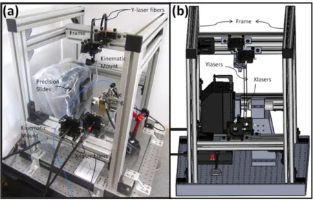
To address the increasing demand in miniature components, an ultra-precision miniature machine tool (MMT) was designed and developed at Advanced Mi-crosystem Technologies Laboratory of Bilkent University (see Figure 3.1 (a)). This MMT includes precision three-axis nano-positioning slides with 60 mm x 60 mm x 60 mm workspace, high positioning accuracy and positioning resolution, miniature ultra high-speed (UHS) spindles with maximum 160,000 rpm rotational speed, a miniature force dynamometer, and a microscope.
This chapter presents the procedure we followed to design and build a 3-axis miniature machine tool that is capable of achieving significantly higher cutting speeds and producing three dimensional features in metals, polymers and differ-ent materials. First, the major subsystems of the designed MMT are introduced. Next, static and dynamic finite element analysis to design mechanical parts for integration of the spindle are presented. Finally, integration of the machine com-ponents using computer aided drawings and precision alignment method are dis-cussed.
CHAPTER 3. DESIGN AND CONSTRUCTION OF MMT 16
Figure 3.1: (a) The ultra-precision miniature machine tool, (b) the zoomed in machining area
3.1
Subsystems of the Miniature Machine Tool
The major subsystems such as high-precision positioning subsystem, motion con-trol subsystem, miniature ultra-high-speed (UHS) spindle subsystem and process monitoring subsystem of the designed 3-axis miniature machining center are dis-cussed in this section.
3.1.1
High-precision positioning subsystem
To facilitate relative motion between tool and workpiece, the positioning subsys-tem is necessary. Since the slides move the workpiece attached on them during machining (see Figure 3.1 (b)), precision of the positioning subsystem affects the output quality of the micro-manufacturing processes. Therefore, it is necessary to ensure that positioning accuracy and resolution of the stages provide the required performance for successful application of micro-manufacturing. Considering the desired accuracy level and special characteristics of micro-machining, available high accuracy positioning systems in the industry has been investigated. After careful investigations of the available products in the market, a three-axis stage Aerotech ANT130-XYZ plus was used. The technical specifications of the stages are provided in the Table 3.1.
CHAPTER 3. DESIGN AND CONSTRUCTION OF MMT 17
Table 3.1: Specifications of the slides [1]
X-Axis Y-axis Z-axis
Aerotech Type ANT130-060-L-PLUS ANT130-060-L-PLUS ANT130-60-L-Z-PLUS
Travel 60mm 60mm 60mm
Accuracy ±250nm ±250nm ±300nm
Resolution 1nm 1nm 2nm
Maximum Force 23N 23N 23N
Maximum Speed 350mm/s 350mm/s 200mm/s
Table 3.1 shows that the ultra-precision positioning stages of the devel-oped miniature machining center are capable of achieving successful micro-manufacturing applications due to their advanced properties such as relatively higher positioning accuracy and positioning resolution.
3.1.2
Motion control subsystem
The ultra-high precision positioning stages of the MMT are driven by brush-less linear servomotor. The motion control subsystem includes a computer, an automation 3200 (A3200) Multi-Axis Machine Controller and the software for Computer Aided Manufacturing (CAM) and motion control.
The positioning stages have their encoders on them to measure their position and to provide feedback during well-known PID control, which is used to satisfy commanded position. The slides are programmed with G-codes for moving the workpiece attached on them (see Figure 3.1 (b)) such that the desired geometry is machined on the workpiece.
G-codes can be created manually or using a suitable CAM program. The part designed using a computed aided drawing (CAD) software is imported in the CAM program. The cutting tool and machining parameters are selected to generate the G-codes to machine the part. Finally, the G-codes are uploaded to the stage controller software. Due to capabilities of the controller and CAM programs, complex motions for manufacturing three dimensional (3D) parts with complicated geometry features can be generated.
CHAPTER 3. DESIGN AND CONSTRUCTION OF MMT 18
3.1.3
Miniature ultra-high-speed (UHS) spindle
subsys-tem
In order to machine micro-scale features, micro-scale cutting tools (milling, drilling) with diameters as small as 10 µm are used. To attain effective ma-terial removal rates while using micro-scale tooling, ultra-high-speed (≥ 20000 rpm) miniature spindles are utilized during micro-milling [82]. Furthermore, in order to effectively study the machining processes at feed values of a few microm-eters per cutting tooth, a spindle with submicron runout (spindle axis offset) is desired.
In the developed MMT, two types of NSK Nakanishi brand miniature ultra-high speed spindles (miniature ultra-ultra-high speed air-bearing air-turbine spindle and miniature ultra high speed ceramic bearing electrical spindle) are utilized to attain necessary cutting speeds.
3.1.3.1 Miniature ultra-high-speed (UHS) air-bearing air-turbine spindle
The first type of spindle used in the developed MMT is the miniature ultra-high speed air-bearing air-turbine spindle with maximum 160,000 rpm rotational speed and a 3mm precision collet. The technical specifications of this spindle are provided in Table 3.2.
Table 3.2: Specifications of the air-turbine spindle [2]
Type Maximum speed Max.Power Output Spindle Accuracy Diameter Air-turbine 160,000 rpm 14 W 1 µm 40mm
Table 3.2 shows that the miniature ultra-high-speed air-bearing air-turbine spindle provides the required performance for successful application of micro-machining due to its high precision and high rotational speed. Furthermore, the air-bearing mechanism means this spindle produces low vibration or heat [2].
CHAPTER 3. DESIGN AND CONSTRUCTION OF MMT 19
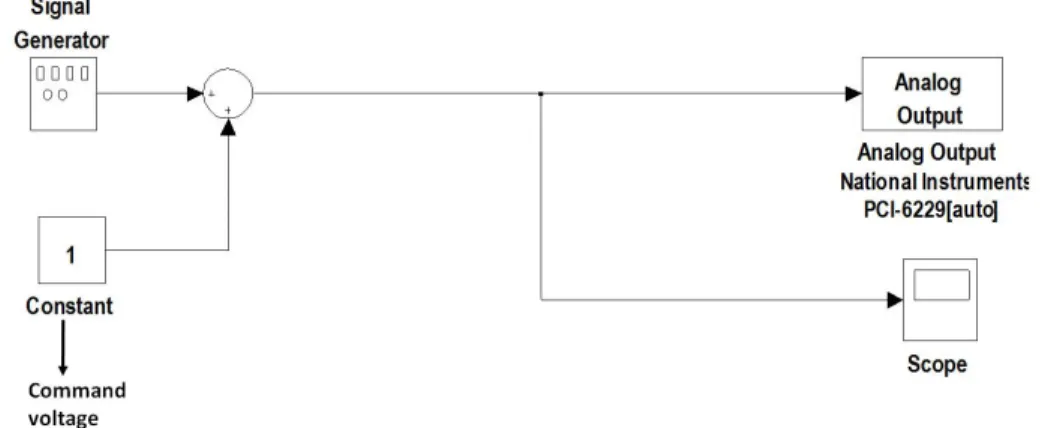
The air bearing spindle does not have a speed sensor or a speed controller. Hence, a non-contact infrared (IR) sensor (Monarch Instruments IRS-W) was used for measuring the speed. In the developed MMT, infrared sensor was con-nected to Monarch ACT-3X tachometer which transforms the coming voltage into rotational speed to visualize spindle speed directly. The IR sensor can measure speeds between 1-999,990 rpm. Due to fluctuating air pressure and varying ma-chining load on the spindle, the spindle speed changes during mama-chining. A speed control mechanism is necessary to keep the speed constant. The speed control system includes the IR sensor for feedback, a mini proportional solenoid valve for varying the inlet pressure to the spindle, a data acquisition card (National In-struments PCI-6229), and a control environment such as MATLAB/SIMULINK R2008a and LABVIEW 2010 environment. The representation of the speed con-trol can be seen in Figure 3.2.
Figure 3.2: General block diagram for speed control
The first step in the speed control is to acquire the spindle speed in control environment. In order to achieve this, the connection between computer and infrared sensor was provided through the data acquisition card and the connector block of this card. Subsequently, the analog output terminals of the tachometer shown in Figure 3.3 was connected to the analog input terminals of the connector block. Finally, spindle speed in terms of voltage between 0 and 5 V was obtained using the analog voltage output option of tachometer.
CHAPTER 3. DESIGN AND CONSTRUCTION OF MMT 20
Figure 3.3: Analog option of the Tachometer
Although this tachometer is capable of measuring 1 to 999,990 RPM range, it is also possible to adjust zero scale (0SCALE) and full scale (FSCALE) values of this tachometer according to the type of application. PM Remote Tachometer software and RS232 to RS232 serial interface can be used to adjust these values. The standard analog output has 32,000 steps from zero to full scale. This full scale value is the value at which the analog outputs are at a maximum, 5Vdc and this zero scale value is the value at which the analog outputs are at a mini-mum, 0Vdc, and the spindle speed will be linear between 0SCALE and FSCALE. Since the number of steps between 0SCALE and FSCALE is constant, increasing the difference between these values will decrease the resolution. Therefore, the measurement range of the tachometer is usually set to give a reasonable working range for the analog input.
In the MMT, in order to provide reasonable working range for air-turbine spindle, 0SCALE and FSCALE values were set to 8,000 rpm and 200,000 rpm, respectively. Using these values and corresponding voltages, the linear relation-ship between voltage and spindle speed was represented as shown in Figure 3.4.
CHAPTER 3. DESIGN AND CONSTRUCTION OF MMT 21
Then, the mathematical relationship between voltage and spindle speed was derived based on Figure 3.4.
Slope = y2− y1 x2− x1
= 200, 000 − 8, 000
5 − 0 = 38, 400 (3.1)
SpindleSpeed = Slope ∗ V oltage + 0SCALE = 38, 400 ∗ V oltage + 8, 000 (3.2)
Equation 3.2 can be used to find corresponding spindle speed for a given voltage value. It is also possible to find resolution of the measurement with known steps from 0SCALE to FSCALE using Equation 3.3.
Resolution = F SCALE − 0SCALE N umberof Steps =
200, 000 − 8, 000
32, 000 = 6rpm (3.3) It is clear that changing 0SCALE and FSCALE of the tachometer improved the resolution from 32 rpm to 6 rpm.
To acquire actual spindle speed in MATLAB/SIMULINK environment, Equa-tion 3.2 was represented by blocks available in SIMULINK as shown in Figure 3.5. The real time acquisition of the spindle speed was achieved by interfac-ing MATLAB/SIMULINK and data acquisition card usinterfac-ing Real Time Windows Target.
CHAPTER 3. DESIGN AND CONSTRUCTION OF MMT 22
Block diagram in Figure 3.5 transforms coming voltage from the sensor into rotational speed and gives the actual spindle speed. Now, acquiring actual spindle speed is achieved for the use of speed control.
Next, calibration of the valve was completed. Proper connections between signal amplifier and external power supply, signal amplifier and mini proportional solenoid valve and, signal amplifier and DAQ connector block were made as shown Figure 3.6 (b).
Figure 3.6: (a) Signal Amplifier (b) Signal Amplifier Connections
To switch the signal amplifier on, it is recommended to supply 9-32 VDC to the signal amplifier. An external power supply was used in MMT to supply this voltage. As a result of many trials, it was recognized that having supply voltage close to the upper limit provides better performance. Therefore, 30 V supply voltage which is the maximum voltage that available power supply can reach was supplied and red power led shown in Figure 3.6 (a) was glowed.
CHAPTER 3. DESIGN AND CONSTRUCTION OF MMT 23
Then, to supply command voltage to the signal amplifier and make the yellow output indicator led glowed , the block diagram created in Simulink (see Figure 3.7) was used. Since it is suggested to use 0-10 V command voltage, the cali-bration was achieved between these voltage values using Imax and Imin screws shown in Figure 3.6 (a) and changing the constant voltage value available in the block diagram.
On the other hand, pressure oscillation on the pressure indicator of air tur-bine was a significant challenge during calibration. Firstly, although the whole speed range (Analog output:0-10 V and corresponding spindle speeds 0-165,000 rpm, respectively) was covered at 0.52 MPa pressure by adjusting the Imax and Imin screws, it was not possible to obtain stable air-turbine pressure indicator for these conditions. Then, considering applications of MMT, Imax and Imin screws were adjusted to cover the speed range of 0-155,000 rpm at 0.5 Mpa. Although oscillation was decreased, it was still there. As suggested, dither frequency and dither amplitude screws (see Figure 3.6 (a)) were adjusted to prevent this oscil-lation. It was observed that dither amplitude has a little effect on oscillation but dither frequency affects oscillation directly. After preventing pressure oscillation by adjusting the dither frequency screw, valve calibration results listed in Table 3.3 were obtained.
Table 3.3: Calibration results
Voltage 0 1 2 3 4 5 6 7 8 9 10
Speed 4,300 7,900 18,000 37,000 71,000 114,000 138,000 150,000 153,400 154,100 155,000
The results shown in 3.3 indicates that valve was calibrated such that spindle speed of 0-155,000 rpm can be controlled by supplying controlled voltage between 0-10 V to the signal amplifier which amplifies the voltage and gives it to solenoid valve to adjust the spindle speed.
Finally, obtaining desired spindle speed requires to control command voltage in real time. Therefore, a well-known PID strategy (see Figure 3.8) was applied to control the spindle speed and its proportional (Kp), integral (Ki) and derivative (Kd) gain constants were tuned using Ziegler-Nichols rule.
CHAPTER 3. DESIGN AND CONSTRUCTION OF MMT 24
Figure 3.8: PID control block diagram created in SIMULINK
The lower part of this block diagram is exactly same with the block diagram used for acquiring spindle speed and the upper part is used to supply neces-sary command voltage to the signal amplifier by comparing the desired spindle speed and actual spindle speed. Furthermore, saturation block used in the block diagram plays an important role especially during the tuning process because it limits the analog output voltage between 0 and 10 V, and prevents signal amplifier and valve damage.
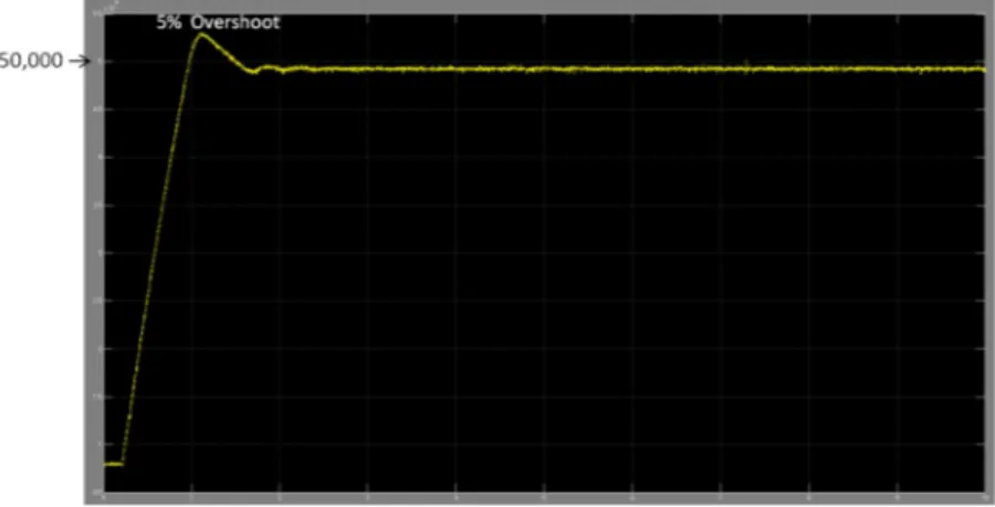
The successful spindle speed control in MATLAB/SIMULINK was achieved using the block diagram shown in Figure 3.8 and step response of the system for different spindle speeds such as 50,000 and 100,000 rpm are given in Figure 3.9 and Figure 3.10, respectively.
CHAPTER 3. DESIGN AND CONSTRUCTION OF MMT 25
Figure 3.10: Step Response for the desired spindle speed of 100,000 rpm
Those figures show that maximum overshoot 5 percent occurs at lower speeds and it decreases as the spindle speed increases. On the other hand, maximum settling time around 3 second occurs at higher speeds and it decreases as the spindle speed decreases.
Although the spindle speed control was achieved using the trial version MAT-LAB/SIMULINK environment and its Real Time Workshop toolbox, it was de-cided to buy LABVIEW for real time applications. LABVIEW was selected because it is an environment designed professionally for relatively higher accu-racy and better performance, and it is designed by the manufacturer of the data acquisition cards that are used for the experiments and control applications in the MMT. Furthermore, it was aimed to prevent sudden stop of the program due to the memory problems in MATLAB/SIMULINK by using LABVIEW. Therefore, the speed control learned and achieved by using SIMULINK was also conducted in LABVIEW 2010 environment (see Figure 3.11) to prevent possible errors in the speed control.
Although it is possible to achieve same control using MATLAB/SIMULINK or LABVIEW, it was realized that LABVIEW is more flexible than MAT-LAB/SIMULINK. It has more options and allows users to create more complex block diagrams using less number of blocks.
CHAPTER 3. DESIGN AND CONSTRUCTION OF MMT 26
Figure 3.11: PID control block Diagram created in LABVIEW
Since it is an environment created by the manufacturer of the data acquisition cards, DAQ assistant blocks (see Figure 3.11) give the properties of the data acquisition card, which is actually good for proper connections and sampling time selection. Due to LABVIEW, the users of the MMT do not have to understand the block diagram and control, they can use only the front panel of the LABVIEW (see Figure 3.12) created by professional engineers.
CHAPTER 3. DESIGN AND CONSTRUCTION OF MMT 27
3.1.3.2 Miniature ultra-high-speed (UHS) ceramic bearing electrical spindle
Miniature air bearing air turbine spindle is not suggested to use under the spindle speed of 50,000 rpm because of the sudden torque decrease. Therefore, a new type of miniature spindle providing enough torque between the rotational speed of 1,000-50,000 rpm was also utilized during micro-machining. It is miniature ultra-high-speed (UHS) ceramic bearing electrical spindle with 50,000 rpm maximum rotational speed and 2, 3, 3.175 and 4 mm collets. The technical specifications of this spindle are provided in Table 3.4.
Table 3.4: Specifications of the electrical spindle [3]
Type Maximum speed Max.Power Output Spindle Accuracy Diameter Electrical 50,000 rpm 350 W ≤ 2 µm 40mm
Table 3.4 indicates that maximum power output of miniature ceramic bear-ing electrical spindle (350 W) is much higher than that of air bearbear-ing air turbine spindle (14 W). Therefore, electrical spindle can provide relatively higher torque which makes electrical spindle capable of machining hard materials such as stain-less steel and ceramic. Another advantage of this spindle is not requiring speed control because it has its own controller which is working with electricity. On the other hand, the accuracy of air-bearing air-turbine spindle (1 µm) is better than that of ceramic bearing electrical spindle (2 µm) and smaller cutting tool diameters can be achieved with air bearing air-turbine spindle because it provides relatively higher spindle speed to reach desired cutting velocity for small cutting tool diameters.
To sum up, the specifications of miniature ultra high speed ceramic bearing electrical spindle are good enough for successful application of micro-machining when lower cutting velocity and high torque are required. Utilizing both electri-cal and air-turbine spindle makes the designed miniature machine tool capable of achieving higher cutting speeds and producing three dimensional features on a variety of engineering materials such as polymers, metals, ceramics and compos-ites.
![Figure 1.1: Applications and market share of micro systems [5]](https://thumb-eu.123doks.com/thumbv2/9libnet/5666574.113353/22.918.221.742.730.1026/figure-applications-market-share-micro-systems.webp)


![[Sadi Işılay'ın hayatı]](data:image/gif;base64,R0lGODlhAQABAIAAAP///wAAACH5BAEAAAAALAAAAAABAAEAAAICRAEAOw==)