APPLICATION OF ABLATION COOLING
TO CATARACT SURGERY TECHNIQUE
USING ALL-FIBRE BURST-MODE LASER
a thesis submitted to
the graduate school of engineering and science
of bilkent university
in partial fulfillment of the requirements for
the degree of
master of science
in
electrical and electronics engineering
By
Denizhan Koray Kesim
January, 2016
APPLICATION OF ABLATION COOLING TO CATARACT SURGERY TECHNIQUE USING ALL-FIBRE BURST-MODE LASER
By Denizhan Koray Kesim January, 2016
We certify that we have read this thesis and that in our opinion it is fully adequate, in scope and in quality, as a thesis for the degree of Master of Science.
F. ¨Omer ˙Ilday(Advisor)
Ergin Atalar
Nurullah C¸ a˘gıl
Approved for the Graduate School of Engineering and Science:
Levent Onural
ABSTRACT
APPLICATION OF ABLATION COOLING TO
CATARACT SURGERY TECHNIQUE USING
ALL-FIBRE BURST-MODE LASER
Denizhan Koray Kesim
M.S. in Electrical and Electronics Engineering Advisor: F. ¨Omer ˙Ilday
January, 2016
Cataract is the most common cause of preventable blindness in the world. Each year more than 19 million operations are performed to treat cataract. While his-tory of cataract surgery goes as far as 2000 BC, beginning with the last quarter of the 20th century, cataract surgery procedures has benefited from advancements in ophthalmology such as phaco-emulsification, intra-ocular lens (IOL) and pre-cision tools. There was another transformation of special interest to this thesis: In 2009, the cataract surgery was performed on a human being using a femtosec-ond laser for the first. Use of lasers has since gathered much attention for their high precision and repeatability in cataract surgery, but there are still challenges that their prevent wide-spread adaptation. The leading challenges can roughly be group into technical and fundamental. The technical challenges include the high cost, complexity and bulk of the associated laser technology. The more fundamen-tal challenges relates to the interaction of ultrafast pulses with tissue. Namely, there is always interest in further reducing collateral damage and post-operation complications, which can potentially be done by reducing required pulse energies or average powers. Such an advance would also simplify the required laser tech-nology indirectly. The principle aim of thesis has been to help overcome these challenges.
In this thesis, a Yb-doped fibre laser system generating femtosecond pulses was designed to exploit recently discovered ablation-cooled laser-material removal technique. The laser system was then integrated with optical coherence tomogra-phy (OCT) for in-situ imaging during cataract surgery. In order to keep required average powers low, ablation-cooled regime is accessed through burst-mode opera-tion of the laser. This custom-built system aims to enhance further the procedure
iv
with lower collateral tissue damage, cleaner, efficient cuts with a compact and robust structure. Preliminary experiments have been conducted on blood agar, plexiglas and extracted bovine eyes comparing the new ablation-cooled regime with the traditional regime. All experiments indicate that this regime achieves ablation with smaller pulse energies and reduced thermal effects to nearby tissue. Specifically, the pulse fluency required for corneal incision is decreased by a factor of ∼15 compared to previous publications. The system has been developed into a transportable laboratory prototype, ready to be used by medical doctors through custom-developed computer control software.
Keywords: Fibre Laser, OCT, Burst Mode, Biomedical Application, Tissue Pro-cessing, Cataract Surgery, Ablation Cooling.
¨
OZET
ABLASYON SO ˘
GUTMANIN KATARAKT AMELIYATI
˙IC¸˙IN K ¨
UME-MODLU F˙IBER LAZER ˙ILE
UYGULAMASI
Denizhan Koray Kesim
Elektrik Elektronik M¨uhendisli˘gi, Y¨uksek Lisans Tez Danı¸smanı: F. ¨Omer ˙Ilday
Ocak, 2016
Katarakt ¨onlenebilir k¨orl¨u˘g¨un en yaygın sebebidir. Her yıl 19 milyondan fazla insan katarakt ameliyatı olmaktadır. Bu operasyonun tarihi millattan ¨once 2000 yıllarına dek uzanmasının yanında, 20. y¨uzyılın son ¸ceyre˘ginde ba¸slamak ¨
uzere, katarakt ameliyatları i¸cin kullanılan y¨ontemler de g¨oz bilimindeki ¨onem te¸skil eden geli¸smeler sayesinde (intraok¨uler lens, fako em¨ulsifikasyon, hassas cerrahi aletler) ¨onemli a¸samalar kaydedildi. Bu tezin ¨uzerinde ¨ozel olarak durdu˘gu bir de˘gi¸sim daha var: 2009 yılından bu yana femtosaniye laser teknolo-jisi ilk defa katarakt ameliyatlarında insanlar ¨uzerinde uygulandı. Lazerlerin kullanımı, ¨ozellikle y¨uksek hassasiyetleri ve tekrarlanabilirlikleri a¸cısından tercih ediliyor. Femtosaniye katarakt cerrahisi teknolojisinin geli¸smeye a¸cık tarafları yaygın kullanılabilmesinin ¨on¨une ge¸ciyor. Bu zorluklar temel ve teknik olarak ikiye ayrılabilir. Teknik zorluklar olarak, y¨uksek maliyet, sistemin boyuları ve karma¸sıklı˘gı g¨osterilebilir. Daha temel zorluklar ise ultrahızlı atımların doku ile olan etkile¸siminden kaynaklanmaktadır. S¸¨oyle ki, istenmeyen ¸cevresel hasarların ve operasyon sonrası komplikasyonların azaltılması her zaman istenilen bir du-rum, ki bu da potansiyel olarak atım enerjisini ya da ortalama g¨uc¨u d¨u¸s¨urerek yapılabilir.Bu geli¸smeler ayrıca gereken lazer teknolojisinin de basitle¸smesine dolaylı yoldan katkı sa˘glayacaktır. Tezin asıl amacı bu zorlukların ¨ustesinden gelinmesine yardım etmektir.
Bu tezde, yeni ke¸sfedilmi¸s lazerle ablasyon so˘gutmalı material kaldırmadan yararlanabilecek Yb katkılı femtosaniye fiber lazer sistemi tasarlanmı¸stır. Lazer sistemi katarakt ameliyatı sırasında g¨or¨unt¨uleme yapabilmesi i¸cin optic koher-ans tomografi (OCT) ile entegrasyonu ger¸cekle¸stirilmi¸stir. Ortalama g¨uc¨u d¨u¸s¨uk tutabilmek i¸cin, ablasyon so˘gutmalı rejim k¨ume-modu ile sa˘glanmı¸stır. Bu ¨ozel
vi
hazırlanmı¸s sistem, k¨u¸c¨ult¨ulm¨u¸s ve g¨uvenilir olarak doku ¨uzerindeki istenmeyen zararları en aza indirgeyerek daha temiz ve verimli kesiler olu¸sturabilmektir. ¨On denemeler agar, pleksiglas ve ¨ol¨u dana g¨oz¨u ¨ornekleri ¨uzerinde ablasyon so˘gutma rejiminin geleneksel rejim ile kıyaslamak amacıyla yapıldı. Deneylerin b¨ut¨un¨u bu rejimin atım enerjisini k¨u¸c¨ult¨up ablasyonu hedefin ¸cevresini daha az ısıtarak yaptı˘gına i¸saret etmektedir. Spesifik olarak korneaya giri¸s i¸cin gereken atım akı¸sı ise ¨onceki yayınlara g¨ore ∼15 kat azaltıldı. Sistem, hekimlerin ¨ozel geli¸stirilmi¸s bilgisayar kontrol programı ¨uzerinden kullanabilece˘gi ta¸sınabilir bir prototip ha-line getirildi.
Anahtar s¨ozc¨ukler : Fiber Lazer, OCT, K¨ume Modu, Biyomedikal Uygulama, Doku ˙I¸sleme, Katarakt Ameliyatı, Ablasyon So˘gutma.
Acknowledgement
I would like to thank Fatih ¨Omer ˙Ilday for opening up the opportunity for me to do research in his group. It was an invaluable experience for me that was educational academically. His advisory thought me the how to do science and conduct research properly which are not only valuable scientifically but other aspect of life too.
I specially want to express my gratitude to Hamit Kalaycıo˘glu for his end-less patience with me. Thanks to his knowledge and discussions, I learned a lot. The fibre laser system developed was based on burst-mode fibre lasers first demonstrated by him.
I would like to thank Can Kerse for intruducing me to group and inspiring me to do research.
I would like to thank Nurullah C¸ a˘gıl and Mehmet A¸sık for their valuable counselling and guidance through out whole project.
I would like to thank my parents, Servet Kesim and B¨ulent Kesim, and my sister, Yaprak ¨Oykum Kesim for their endless love and support. They made me who I am today. Their place in my life is irreplaceable and most enjoyable. I would also like to thank to Beg¨um Akbay for her patience and support during this tiring period. Thank you for entering my life and making it more beautiful than I can ever imagine.
Last, but not least, I thank to ¨Ozg¨un Yavuz, U˘gur Te˘gin, Ahmet Turnalı, Sinem Yılmaz, Onur Tokel, Gaith Makey, Ihor Pavlov, Parviz Elahi, ¨Onder Ak¸caalan for their friendship and enjoyable conversations.
This work is financially supported by T ¨UB˙ITAK Project 112T980, Project 114F256 and Heath Ministry of Turkey.
Contents
1 Introduction 1 1.1 Cataract . . . 2 1.1.1 Cataract Surgery . . . 2 1.2 Lasers . . . 3 1.2.1 Fibre Lasers . . . 41.3 Multi-photon Absorption and Photodisruption . . . 6
1.3.1 Ablation-Cooled Material Removal . . . 6
2 Cataract Surgery System 9 2.1 Laser . . . 9
2.1.1 Oscillator . . . 10
2.1.2 Preamplifier . . . 11
2.1.3 Power Amplifier . . . 12
CONTENTS ix
2.2 Electronics . . . 14
2.3 Optical Coherence Tomography . . . 16
2.3.1 Integration with Laser . . . 18
2.4 Software . . . 19
3 Methodology 21 3.1 Preparations . . . 21
3.2 Blood Agar Experiments . . . 22
3.2.1 Straight Cuts . . . 23
3.2.2 Volume Ablation . . . 23
3.3 PMMA Experiments . . . 24
3.4 Bovine Eye Experiments (Corneal Flap) . . . 24
4 Results 27 4.1 Agar Experiments . . . 27
4.2 PMMA Experiments . . . 28
4.3 Bovine Eye Experiments (Corneal Flap) . . . 29
5 Conclusion 32
CONTENTS x
B XYZ Stage Details 42
B.1 Elevator (Z-stage) . . . 43
List of Figures
1.1 Gray are is coating, green area is cladding, blue is core. In double clad fibers, there is an additional layer of cladding which is shown in red . . . 5
1.2 (a) Pulses are separated equally. Repetition rate can go from in the order of Hz to order of MHz. (b) Pulse to pulse repetition rate is typically very high (in the order of hundreds of MHz to GHz) but burst to burst repetition rate is typically much lower . . . 8
2.1 On far left corner, oscillator box is visible. On the other left corner is grating compressor. Right side of the table is reserved for OCT probe, XY stage and elevator for experiments. . . 10
2.2 all-normal dispersion Oscillator: Produces 200 mW power at 91 MHz repetition rate . . . 10
2.3 Oscillator Output Spectrum, 12 nm FWHM spectrum, 200 mW output power, 2.75 ps FWHM pulse length . . . 11
2.4 Coupler Spectrum after stretch fibre . . . 12
LIST OF FIGURES xii
2.6 Incoming laser hits the first grating and its spectral components are separated spatially. With the help of second grating and mirror, each spectral component experience delay linearly proportional to their wavelengths, thus compressing the pulse temporally . . . 14
2.7 Burst Mode Operation(change for new oscillator) . . . 15
2.8 Potentiometer can adjust the DC bias from 0V to 2.7V. BASYS2 has its clocking threshold around 1.25V. . . 15
2.9 Different wavelengths reflected from corresponding depths and in-terfere with reference beam to construct the final image. Interfer-ence beam is measured by a detector array . . . 16
2.10 Screenshot of ThorImage OCT software. It handles the data com-ing from OCT engine. Imaging type, resolution, speed can be chosen. Real time camera feed can also be seen within ThorIm-age. It has some additional filters and processing to reduce the distortions. . . 17
2.11 Processing beam (red) is inserted via dichroic mirror. Imaging beam (green) travels on its usual but elongated path. A pro-grammable shutter is placed on path of processing beam. . . 19
2.12 Screenshot of the software. One can choose between 3 predeter-mined patterns with 2 different options (wall structure & raster). It can also adjust the initial height of the elevator and the intensity of OCT probe lighting. . . 20
3.1 Agar is placed on petri dish filled with tap water. Occasionally, few drops of water is dripped on top to prevent drying out locally. 23
3.2 Extracted cornea is place on holder. Then it is tightened with a cap (gray). Normal saline is pumped from the tubes which prevents drying out. . . 25
LIST OF FIGURES xiii
3.3 (a) A spring pattern starting from 200 µ below surface, as walls of the flap. (b) constructs the basis of the cap of corneal flap beneath the surface . . . 26
4.1 Lower half of agar is scanned with uniform-mode and upper half is scanned with burst-mode. There are little visible modification on uniform-mode side compared to burst-mode side, seen from OCT image while there are clearly ablation lines on burst-mode side. Pulse energy is kept at 1.7 µJ in both cases. . . 28
4.2 Half of agar is scanned with burst-mode (left side), 1.75 µJ pulse energy and 10 µm separation between each line. Right side is scanned with exactly same parameters, except uniform-mode in-stead of burst-mode with 400 kHz repetition rate. . . 29
4.3 Uniform repetition rate at 400 kHz with pulse energies 900 mW, 1 W and 1.2 W respectively. Each of them is scanned with 10 mm/s 29
4.4 8 pulse per burst with pulse energies 900mW, 1W and 1.2W. Each of them scanned with 10 mm/s with 50 kHz burst repetition rate 30
4.5 24 pulse per burst, 833 nJ pulse energy, repeated at 50 kHz. . . . 31
A.1 Laser Oscillator . . . 40
A.2 Laser Amplifier . . . 41
B.1 Perspective drawings of XYZ stages, The table is able to fix both laser and XYZ stages and will be durable against perturbations. . 42
Chapter 1
Introduction
In this thesis, a novel and recently developed technique, namely, ablation-cooled material removal by ultrafast pulse burst is investigated for the first time in laser processing of biological tissue from an ophthalmologic perspective. A fi-bre laser system is built to test it in the context of cataract surgery. This way, an understanding of the ablation-cooled regime, its practical implementation via burst-mode operation of the laser and its comparison with uniform-mode on bi-ological, transparent subjects will be gained. The principles of ablation-cooled regime are described elsewhere [1] and will not be covered here.
Furthermore, its practical implementation requires burst-mode operation of the laser due to finite speed of beam scanners and in order to minimize power requirements. For this reason, the terms of burst-mode and ablation-cooled ma-terial processing are used interchangeably throughout this thesis. The reader should, however, be aware that not all burst-mode operation corresponds to ablation-cooled regime and that there is a minimum repetition rate, the value of which depends on the thermal diffusivity of the target material and that the pulse energy has to be scaled according to the repetition rate [1].
It will cover the building a compact laser, its integration to a customized opti-cal coherence tomography (OCT) system and its conversion to a capable surgiopti-cal
system with uncomplicated controls since it will be delivered to a hospital to further conduct experiments on live animals. Moreover, some preliminary exper-iments are done as proof of principle on biological and non-biological samples. The results of these experiments are also covered in this thesis.
1.1
Cataract
Cataract is defined as loss in transparency of the lens in the eye [2]. There are a number of causes for this condition [3] but it is mostly related with aging [2, 4] and it is a common problem [5]. Cataract is responsible for about two thirds of preventable visual impairments. It affects nearly 190 million people all over the world [6]. Cataract surgery is also the most performed operation in the world [6].
In the light of these circumstances, any possible improvement over the current techniques will benefit a significant portion of the human population. These im-provements can be in the name of reliability, costs, reduction of post-operation complications, and ease of use. The main focus has been on reducing the compli-cations of operation, cost of laser systems and reduction of required laser powers, which is likely to result in reduction of post-operation complications.
1.1.1
Cataract Surgery
The surgical procedure itself is an ancient practice. First writings regarding ophthalmologic practices were found in the Code of Hammurabi though, it is not clear how they handled cataract. However it is believed, Japanese doctors were performing an operation called couching even before 2000 BC [7]. Around 500 BC, Greeks were certainly using this method. In Dead Sea Scrolls, very first written description of couching can be found.
Medical science has come a long way since ancient times. Currently opacified lens is removed and replaced with intra-ocular lenses [8], tools that allow smaller
incision [9], the state of the art technique of chaco-emulsification [10] and finally lasers to performed capsulotomy (operation on capsule of the lens of the eye) [11].
Chaco-emulsification process will be improved by developing a novel laser without changing the operation itself within the scope of this thesis. In chaco-emulsification, a small incision is made in cornea. Then, lens capsule is either removed altogether or partially. Opacified lens is broken into pieces and sucked afterwards, which can be done with ultrasound or laser depending on preferences. Finally, intra-ocular lens is placed inside the lens capsule [10].
In this procedure, the introduction of the laser is very recent 2009 [12], where capsulotomy and lens fragmentation are performed with a commercial laser [13]. Other surgical devices can take part in corneal incision too [14, 15]. Whether to employ full capabilities of a system is up to the operator who may decide to perform only capsulotomy and do the rest by other means. Today, the advances in cataract surgery continue [16] and any improvement to current situation is usually appreciated.
It is especially important to reduce the pulse energy as it would reduce the size of residual cavitation bubbles after laser processing. Residual gas bubbles can increase the internal pressure of the eye which can lead up to complications after surgery. Additionally, it is important to keep in mind that current refractive laser assisted cataract surgery systems are quite expensive, it can cost between 300,000 and 500,000 USD. Reducing the cost of such systems would make them more available for people especially in underdeveloped and developing countries.
1.2
Lasers
Light amplification by stimulated emission of radiation (LASER) is a common process to emit spatially and temporally coherent light . It can be utilized in nu-merous areas including telecommunication, material processing, imaging, military applications, medicine, precise measurements [17–23].
The laser was invented in 1960 with ruby as gain medium inside a resonating cavity built with mirrors [24]. Ever since, development of lasers continue with new gain materials [25], various types of cavity [26] and other physical phenomena [27] that can be exploited in favor. In addition to those, scientists realized the advantages of using pulsed laser radiation compared to continuous wave laser [28] especially for some material processing applications which would benefit from nonlinear processes at high peak intensities and low average powers which reduce thermal side effects. Furthermore, multi-photon processing is possible with pulses (Explained in 1.2). There are several ways of generating pulsed laser radiation, among which actively modulating gain (gain switching), loss (Q switching) or output of laser constitute to relatively straight forward ones.
Mode-locking is another way of generating pulse trains from laser which in-volves obtaining short pulses through coupling of modes inside the resonator cavity.
Further, there is passive mode-locking method as a way of generating such radiation which enables the formation of shortest pulses. Passive mode-locking where pulses are created in cavity by exploiting physical phenomena, without interfering actively [29] requires a saturable absorber [30] to achieve mode-locking.
1.2.1
Fibre Lasers
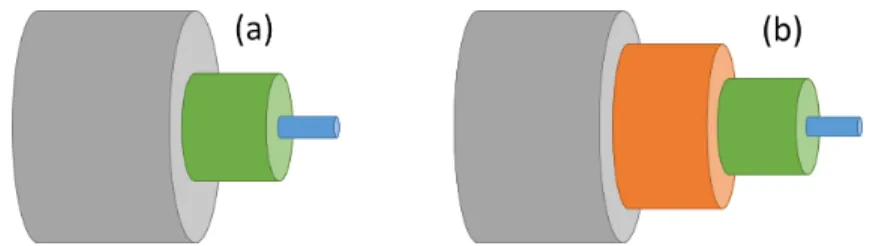
In fibre lasers, light propagates and gets amplified inside a fibre waveguide. Dop-ing of the gain fibre determines the central wavelength of the laser. Optical fibers consist of 3 main parts: core where laser beam propagates, cladding which con-fines the core and coating that protects the fibre (Fig. 1.1 (a)). In some fibers double cladding (Fig. 1.1 (b)) structure allows for high power amplification.
However, nonlinearity inside the fibers produces some new challenges. Also go-ing to higher average powers is very difficult because of heatgo-ing which can damage the fibre itself. For that reason, fibre lasers could not reach high powers for a long time. As a solution, chirped pulse amplification is proposed which elevated the
Figure 1.1: Gray are is coating, green area is cladding, blue is core. In double clad fibers, there is an additional layer of cladding which is shown in red
laser technology to next level [31]. Fires already are highly dispersive medium, that they ease up the process. In this method laser pulses are stretched, usually exploiting this dispersive effects, before amplification. As pulses are stretched, peak powers dropped which in return allowed much greater amplifications. Ad-ditionally, mode-lock of such lasers is sensitive to environmental effects such as temperature. As a result heat stabilization and boxing is usually required.
Fires can be bent to a certain degree which provides great advantages in terms of packaging and robustness. Fibre lasers can be more compact and stable than solid state lasers as guiding inside fibers isolates against external effects to a great extent. They can produce nearly diffraction limited beam since the wave-guide properties eliminate distortions (hence the great optical quality of the beam is achieved.
Finally, building a fibre laser is cost effective compared to solid state lasers. Considering the cost of cataract surgery systems that are currently approved, decreasing the cost of such a system would make it more available for masses. Especially for underdeveloped and developing countries, who might be reluctant to spare funds for purchasing an expensive surgery device and maintaining it.
1.3
Multi-photon Absorption and
Photodisrup-tion
In laser assisted cataract surgery, photo disruption process is resorted. In photo disruption, plasma is formed via nonlinear absorption which is followed by a shock wave, leaving a cavitation bubble behind and disrupting the tissue [32]. When a train of pulses are scanned, cavitation bubbles merge and cut through tissue. Typically, six or more photons are required for photo disruption to take place in transparent tissue. That sets up the intensity of laser beam to very high so that the probability of nonlinear absorption is substantial.
The intensity is greatest at the focal point of beam. One way to achieve this is to compress pulses as much as possible hence ultra short pulses. Shorter pulses reduce the photo disruption threshold [33]. The other way is sharp focusing the beam which would mean a more localized beam and higher intensity. This would also localize the photo disruption which limit the processed volume. A sharper focus also enables precise cutting but is very slow. In order to speed up the cutting, pulse energy is increased so that visible plasma is formed which can cleave the tissue. As a result, instead of sending pulses tangent to each other, spot separation can be increased by increasing scanning speed.
Non-linear absorption also makes subsurface modifications possible. Anywhere out of focus of beam do not go through any absorption since single photon energy is not sufficient. Propagating beam is mostly effected by scattering within the tissue.
1.3.1
Ablation-Cooled Material Removal
In literature, it is observed that higher repetition rates give better ablation per-formances [34]. When the repetition rate exceeds a certain value that the heat diffusion time for the material target is less then the time it takes for the next pulse to arrive, laser material interaction passes to ablation-cooled regime [35].
High repetition rate leaves no time for heat diffusion on sample, a technique used in space shuttles for a long time [36, 37]. Heat trapped in ablation region from the leading pulse is ablated by consecutive pulses. This way total heat accumula-tion on sample is kept at minimum and more volume is removed with same pulse energies. Heat accumulated in ablated region lowers the ablation threshold in that area by pushing electron into higher energy levels. Lower ablation threshold lets usage of pulses with less energy, which in turn reduces the collateral dam-age. However, the average power required for such repetition rates are extremely high that it is not practical. The laser complexity and cost of the laser makes it undesirable.
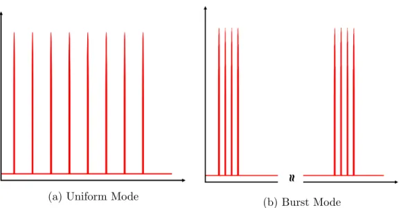
As a result, burst-mode operation is adapted. In this novel operating mode, which is the unique distribution of pulses in time where a number of them are gathered in groups which in turn repeated at much lower repetition rates [38–40] (Fig. 1.2 (b)), would overcome those impracticalities. This kind of distribu-tion of pulses may require some addidistribu-tional steps in laser amplifier, like pulsed pumping [39] and shaping of pulse train before amplification [41], however, over-all complexity of laser would go down with need for high average power. Burst mode operation is especially beneficial in fibre lasers where it is relatively easy to get high repetition rates from oscillator.
The heat increase of the material due to ablation is mostly related to the pulse energy. Each pulse increases the temperature of the target by a certain amount while ablating. However in burst-mode operation, when it is employed in ablation-cooled regime, the temperature increase is mostly carried away with ablated material. The net temperature increase of the target, when ablated in ablation-cooled regime, will be contributed by last few pulses inside the burst instead of all of them. That is because the heat contribution by initial pulses are already gone.
A fair comparison of burst-mode operation with traditional operation mode, namely uniform-mode (Fig. 1.2), can be done by adjusting the repetition rate to be equal to effective repetition rate of burst-mode operation while keeping the pulse energy same. The effective repetition rate of burst-mode can be found by
(a) Uniform Mode (b) Burst Mode
Figure 1.2: (a) Pulses are separated equally. Repetition rate can go from in the order of Hz to order of MHz. (b) Pulse to pulse repetition rate is typically very high (in the order of hundreds of MHz to GHz) but burst to burst repetition rate is typically much lower
multiplying the number of pulses inside each burst with burst-to-burst repetition rate. So both will have same average power as well as same pulse energy. This would mean the laser complexity for creating both pulse trains will be equivalent.
Properties of burst-mode mentioned above renders burst-mode operation on soft tissue most favorable. It can perform ablation on tissue with minimal ther-mal damage to the surrounding tissue without reducing ablated volume while increasing the speed of processing.
Chapter 2
Cataract Surgery System
2.1
Laser
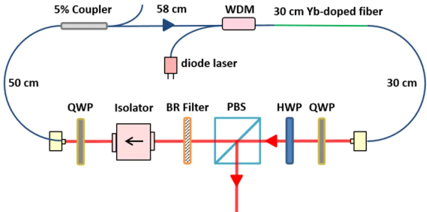
A new laser system is built which can support high repetition rate bursts, enough energy to perform ophthalmic tissue processing and short pulses. Master Oscilla-tor Power Amplifier (MOPA) architecture and Fibre medium is chosen for com-pactness and stability issues (Figure 2.1). Laser design consists of an all-normal dispersion oscillator,, stretch fibre, a double-clad forward pumped pre-amplifier and a double-clad backward pumped power amplifier. In addition to them, an AOM is located between pre-amplifier and power amplifier for adjusting the rep-etition rate.
Figure 2.1: On far left corner, oscillator box is visible. On the other left corner is grating compressor. Right side of the table is reserved for OCT probe, XY stage and elevator for experiments.
2.1.1
Oscillator
Laser system is seeded by an all-normal dispersion oscillator [42] which can be seen from Figure 2.2. 30 cm 6/125 Yb-1200 fibre is used as gain medium which is pumped with single mode pump diode. 5% coupler port is connected to a detector and its signal act as clock of FPGA.
Figure 2.2: all-normal dispersion Oscillator: Produces 200 mW power at 91 MHz repetition rate
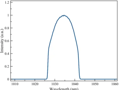
At the output, 12 nm spectral width (Figure 2.3), 185 fs transform limited pulses, 200 mW power is obtained. 140 mW of it is coupled to amplifier input fibre. The repetition rate of the oscillator is 91 MHz. A stable mode-lock can be found with self starting. It is critical to have self starting mode-locking. The laser should not be prone to possible outage and should be turned off if not needed.
Figure 2.3: Oscillator Output Spectrum, 12 nm FWHM spectrum, 200 mW out-put power, 2.75 ps FWHM pulse length
Oscillator diode draws current from 5V power supply which is connected to Argenc diode driver.
2.1.2
Preamplifier
Before the acusto optic modulator (AOM) pulses need to be amplified since AOM will induce a huge loss. Power amplifier will need at least 1 mW power to work properly. Pre-amplifier is constructed from double clad Yb doped fibre is used to reduce the number of laser diodes spent on laser and nonlinear effects inside the fibre.
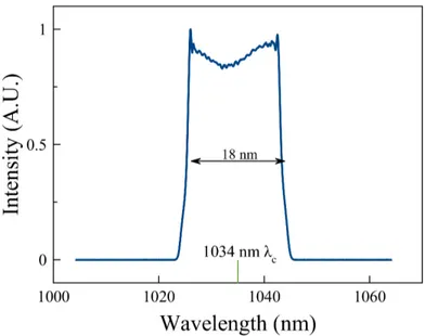
Pulses are stretched with 90 m stretch fibre to reduce nonlinearity during and after amplification. Stretching also increased the spectral width to 18 nm, as seen
from a diagnostics coupler (Figure 2.4).
Figure 2.4: Coupler Spectrum after stretch fibre
Pre-amplifier was first constructed from single clad 6/125 Yb doped fibre. To reach the desired output power, fibre length had to be at least 5 meters. However, this lead to strong Raman stimulation which cause a huge wavelength shift and compression problems. So it had to be changed to double clad 20/125 fibre since pre-amplifier is wanted to be single stage. In the end, 1.5 meters of 20/125 Yb doped fibre for pre-amplifier is spliced. This provided 1.2 W output power. Spectral width increased to 25 nm.
Pre-amplifier pump diode current is supplied by 7.5V 13.6A power supply. PLD of pre-amplifier shares a 5V power supply with power amplifier PLD.
2.1.3
Power Amplifier
1.5 meters of Yb1200 20/125 is used as gain medium to increase absorption as keeping the nonlinearity manageable. After the free-space isolator, 2W output power at 400 kHz repetition rate is achieved.
of power amplifier shares a 5V power supply with pre-amplifier PLD.
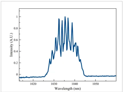
Figure 2.5: Laser Output Spectrum, 11 nm FWHM, 2 W output power, 63 ps
2.1.4
Compression and Laser Output
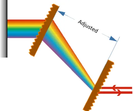
Compression is done by building a grating compressor with two gratings and a mirror (Fig. 2.6). Between two gratings pulses experience negative dispersion. Changing the distance between them determines the amount of negative disper-sion they experienced. Details of grating compressor can be found from [43].
Gratings that are used have 900 lines/mm. Maximum efficiency for 900 lines/mm grating at 1035 nm centre wavelength is 28◦ incident angle to nor-mal axis. Even slight changes at incident angle of light at any of the gratings will result in lower power efficiency. Thus it is very important to align gratings and mirrors associated with grating carefully. From dispersion calculations, the spacing between gratings found to be 70 cm, however precise adjustment was done by hand for the best compression. Maximum efficiency this compressor can reach is 65 % and 60 % is achieved in this system.
As energy of a pulse changes, they experience various amounts of nonlinear-ity so the grating optimization changes for each energy levels. However, after
Figure 2.6: Incoming laser hits the first grating and its spectral components are separated spatially. With the help of second grating and mirror, each spectral component experience delay linearly proportional to their wavelengths, thus com-pressing the pulse temporally
optimizing for the highest pulse energy, change of compressed pulse width was negligible. At the output of compressor highest pulse width that measured is 300 fs FWHM for the desired range of pulse energies.
2.2
Electronics
Commercial diode drivers are used for both amplifiers and oscillator. Argen diode driver is used for oscillator diode. It is compact enough to fit under fibre platform and can supply up to 1 A which is more than enough for oscillator. It also has built in temperature controller for stabilization. Two PLDs are used for pre-amplifier and power amplifier. Those do not have active temperature stabilization but can supply much higher currents, up to 10 A.
Figure 2.7: Burst Mode Operation(change for new oscillator)
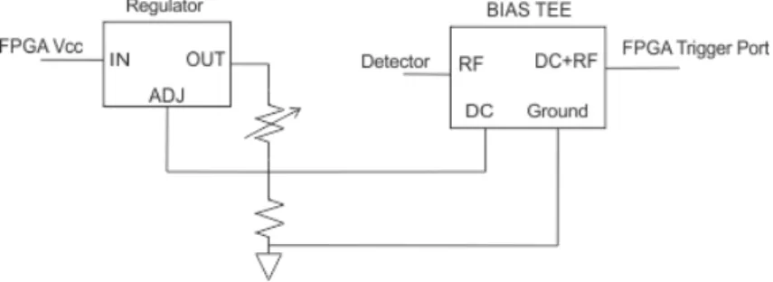
is chosen for its low cost, no heavy computations are necessary for this application. A sensitive detector is connected to coupler output of the oscillator. Detector signal is between 0 V and 200 mV. However FPGA trigger is centred around 1 V. To overcome this, a DC BIAS circuit is built instead of an amplifier. It consists of a 1.25 V regulator and a DC BIAS from Mini Circuits (Fig. 2.8). With the help of a potentiometer, BIAS on detector signal can be adjusted to accordingly.
Figure 2.8: Potentiometer can adjust the DC bias from 0V to 2.7V. BASYS2 has its clocking threshold around 1.25V.
The detector output is connected to JC ports of the FPGA which have des-ignated clocking routes for minimum skew. A VHDL program sends gates with desired width and frequency to AOM driver in order to pick any number of pulses at any repetition rate. Additionally, switches are programmed such that AOM modulation can set to full pass for diagnostics, burst-mode for applications and
uniform-mode for comparison with burst-mode. FPGA needs a separate 5 V, 5 A power supply to isolate it from high currents.
After boxing of the system there will be total of two 7.5V, 13A power supplies and three 5V, 5A power supplies.
2.3
Optical Coherence Tomography
Optical Coherence Tomography (OCT) is the most common imaging device for opthalmologic applications since it presents non-invasive high resolution (equiv-alent to low-power microscope) 3D imaging in soft tissue.
OCT imaging is very similar to ultrasound which relies on broadband sound waves sent to tissue where different frequencies bounce of from corresponding depths (Fig. 2.9). Because it is based on light, the resolution is much higher than ultrasound. Detection is based on low coherence interferometry which greatly increases signal-to-noise ratio (SNR), creating clear images without background noise.
Figure 2.9: Different wavelengths reflected from corresponding depths and in-terfere with reference beam to construct the final image. Inin-terference beam is measured by a detector array
The OCT in this system is a spectral domain OCT (SD-OCT). The inter-ference pattern is detected by an array of detectors. The main disadvantage of
SD-OCT is its decreased signal-to-noise ratio as imaging point moves away from zero delay. Different depths reflect corresponding wavelengths if refractive index changes which interfere with reference light. Measure the interference pattern with an array of detectors provide necessary information to construct 1D depth image. Galvo scanner walk the beam to build up 2D or 3D images from many 1D images. CALLISTO OCT [44] is purchased from Thorlabs as OCT for inte-gration to the system. Its central wavelength is at 930 nm (Super Luminescent diode). Maximum depth possible for imaging is 1.6 mm. It has 4 µm lateral resolution. It came with ThorImage OCT software to handle rendering and other operations regarding the imaging (Fig. 2.10). Moreover, the software develop-ment kit for OCT engine and OCT probe is ordered to be used in custom software development.
Figure 2.10: Screenshot of ThorImage OCT software. It handles the data coming from OCT engine. Imaging type, resolution, speed can be chosen. Real time camera feed can also be seen within ThorImage. It has some additional filters and processing to reduce the distortions.
Modular OCT probe is obtained for its freedom of modification. This is es-pecially important since the processing laser beam should follow the same path with imaging beam which is only possible by modifying the probe.
The focal point of laser is found by using thin lame and moving OCT probe vertically at high power. When plasma on surface is visible, OCT reference arm
can be adjusted to any desired length. It is usually kept at 0 mm to be able to image the sample as deep as possible while processing.
2.3.1
Integration with Laser
Integration of the laser and OCT is essential to accurately target laser on the eye . Planar targeting is done by galvo scanner inside the OCT probe while vertical targeting is done by computerized elevator.
First of all, some modifications on modular probe is done for input laser beam. An additional cage containing a dichroic mirror is placed between galvo scanner and beam splitter. Angle of dichroic mirror is at 45 degrees to achieve maximum power efficiency from laser. With the help of 3 mirrors laser beam is carried along the bridge with elevator. Beam is coming to the top of OCT probe to prevent any interruptions from XY stage. Last mirror that directs the beam downwards should be aligned very carefully perpendicular to ground. Otherwise power may change with elevator movements (Fig. 2.11). After alignments, efficiency from laser output through compressor to target is measured to be 40%.
As a result, both imaging and processing beam follows the same path after additional dichroic mirror, thus allowing imaging and processing to be done one after the other without making any changes. This ensures more precise targeting with OCT images.
LSM03-BB lens is changed with LSM02-BB for sharper focus however it re-duced our field of view (FOV). Due to galvo mirror sizes and f-theta lens on the probe, FOV is about 0.6 mm X 0.6 mm. Although it would not be sufficient for human eye surgery, it is enough for animal experiments.
The efficiency of the integration from compressor output to sample is 40%. It can deliver up to 4 µJ pulse energy on sample. Since the plan is to lower the pulse energy to sub µJ for processing, current efficiency should be enough.
Figure 2.11: Processing beam (red) is inserted via dichroic mirror. Imaging beam (green) travels on its usual but elongated path. A programmable shutter is placed on path of processing beam.
2.4
Software
The system will be used by medical doctors who, are assumed to have no techni-cal knowledge or background on operating a laser, galvo scanner or programming. A reliable and capable program with graphical user interface was necessary. A typical operation would require corneal incision, capsulotomy and lens fragmen-tation. So horizontal and vertical planes are to be created in straight or circular lines.
Thorlabs provided SpectralRadar.dll file for OCT which also can control the galvo scanner inside OCT probe independently. Thus, to avoid any compatibility issues that may rise, the software is written in C++. Integration of shutter and joystick depends on ActiveX. This way a user friendly GUI is also possible with ActiveX controls (Fig. 2.12).
The library works with arbitrary units of length which should be converted to real units. Some trial runs reviled that 1 unit of length of galvo corresponds to 0.5 mm with the lens and galvo integrated.
Figure 2.12: Screenshot of the software. One can choose between 3 predetermined patterns with 2 different options (wall structure & raster). It can also adjust the initial height of the elevator and the intensity of OCT probe lighting.
Every iteration of procedure starts with moving the elevator to desired height. Then the shutter opens for processing beam. Galvo scans the target with chosen pattern and its parameters. After that, shutter closes. It can be repeated with any number of times while changing some parameters in between iterations, i.e. elevator position to create complex patterns.
This software can operate galvo scanner in lines, raster pattern and concentric circles while changing the elevator position simultaneously for 3 dimensional tar-geting of focal point. Speed of galvo scanner can be adjusted via GUI. User can specify how many times to repeat chosen pattern. In the future, this software will be able to render OCT images and CCD camera feed on GUI without the need of commercial software of OCT that Thorlabs provided.
Chapter 3
Methodology
Adequacy of the laser was tested by a series of experiments. Both biological and non-biological were subject to experiments to compare the strengths and weak-nesses of burst-mode with uniform-mode for this particular laser. Explanations of how these experiments were conducted are covered in this chapter.
3.1
Preparations
The focal point of laser is found by using thin lame and moving OCT probe vertically at high power. When plasma on surface is visible, OCT reference arm is adjusted to get the focus to any desired depth on OCT image. It is usually kept at 0 mm to be able to image the sample as deep as possible while processing. Experiments are done on either agar or bovine eyes.
In comparison experiments for uniform-mode with burst-mode, scanning speed is adjusted to create 50 % overlapping between bursts. For direct comparison to the uniform-mode, pulse energy is kept equal to the burst case and scanning speed is adjusted to keep the fluency same with burst-mode. So for 24-pulse bursts repeated at 50 kHz, the scanning speed is set to 0.2 m/s. 50 kHz burst
repetition rate is the lowest it can be set without experiencing Amplified Spon-taneous Emission (ASE) generation. For same scanning speed, uniform-mode repetition rate is set to 1200 kHz at same individual pulse energy. To find the threshold pulse energy in each case of burst-mode and uniform-mode, the pulse energy was increased until continuous cutting occurred for each case.
3.2
Blood Agar Experiments
Agar gel is chosen for its similar optical and mechanical properties to soft tissue [45]. It is widely used as soft tissue phantom. Agar is prepared at 2 % density, 100 grams of water for 2 grams of agar. Solution is cooked with microwave for 2-3 minutes, while stirring ever 20 seconds for homogeneity. Then it is poured in to ice cube trays and refrigerated for 4 hours. After gels are solidified enough, they are kept in tap water inside refrigerator until they are needed. Once prepared, agar gels can be kept up to 2 weeks before the surface deteriorates.
Laser is tested with blood agar before moving on bovine eyes. Agar is placed in a culture dish filled with water to prevent drying out (Fig. 3.1). Drops of water is dripped on top occasionally. However, before processing, top surface is cleaned very softly with a lens cleaning tissue to reduce targeting errors since OCT cannot distinguish water from agar properly. One block of agar could stay under for 2 hours without changing before it starting to lose its physical properties.
These experiment is also done with various pulse energies to find an optimal point. The required pulse energy for agar experiments is higher than cornea so number of pulses is chosen to be per burst to be 8 at 50 kHz to increase individual pulse energy. Uniform mode repetition rate is adjusted to be 400 kHz respectively.
Figure 3.1: Agar is placed on petri dish filled with tap water. Occasionally, few drops of water is dripped on top to prevent drying out locally.
3.2.1
Straight Cuts
Creating ablation lines on surface with both uniform-mode and burst-mode was the first task to be done on agar. Scanning speed is set to 25 mm/s to get 50 % overlapping between bursts. Speed is not changed for uniform-mode to make a fair comparison. Various pulse energies are tested to find a pulse energy that can create smooth lines. A side by side comparison is made by OCT.
3.2.2
Volume Ablation
The system is tested if it is capable to perform patterns that are implemented in surgery properly. The aim was to remove a slice of agar from bulk, as done in refractive eye surgery [46]. It consists of two predetermined patterns, raster scan and spiral. Raster scan is applied on surface and imaged with OCT. Images show how much volume is ablated for a single pass with various pulse energy and scan
speeds.
3.3
PMMA Experiments
PMMA is determined to be the subject for observation of the effects of burst-mode and compare with uniform-burst-mode, when processing occur below surface. The material is mostly transparent to infrared light so we can observe multi-photon absorption and test how threshold changes with burst-mode.
The distance between lines of raster scan is chosen to be 10 µm. Number of pulses for each burst is chosen to be 8, which is enough to observe the effects of burst mode barely. More pulses per burst would have been even better but that would push the laser to its limits. It may not be a concern in burst-mode but in uniform-mode, we couldn’t go that high powers.
1 mm below surface of PMMA is chosen as focal point. Then 1mm x 1mm area is scanned with raster pattern. Scanning speed is set to 10 mm/s for both uniform-mode and burst-mode.
3.4
Bovine Eye Experiments (Corneal Flap)
Bovine cornea is used to test real world application of the cataract surgery system, if the parameters are fitting for such applications. Bovine eyes are collected directly from slaughterhouse and kept at -20 in freezer. Cornea is extracted while the eye is still frozen with lancet. Then, it is unfrozen by putting in normal saline in room temperature. After this, cornea is soaked in glycerine to get rid of excess water.
After unfreezing the cornea it is inserted on to a holder where it is tightened and normal saline is pumped from beneath cornea (Fig. 3.2). A thin lame is placed on top of cornea with saline in between them. Surface tension and pumping
Figure 3.2: Extracted cornea is place on holder. Then it is tightened with a cap (gray). Normal saline is pumped from the tubes which prevents drying out.
keeps cornea in contact with normal saline all the time, preventing drying out. Holder is placed on an elevator for computer controlled z-axis movements. The experiments can be conducted for 1-2 hours before edema occurs in cornea and prevents the processing properly.
Formation of corneal flaps involved cutting concentric circles on horizontal plane first followed by a spring pattern in z direction in the cornea. Edge of biggest circle in former pattern intersect latter from bottom, so that they form shape of a coin. For the spring pattern, laser is focused beneath the bottom surface of cornea about 200 m by using OCT imaging. Then, after scanning each straight line, cornea is lowered in steps of 5 m cutting a line at each height until the top surface is reached (Fig. 3.3 (a)). This is repeated until the surface is reached. Then, concentric circles are applied on horizontal plane by aiming 200 µm beneath the top surface of cornea and scanning the laser where radius is reduced 10 µm each time so that consequent circles are touching each other (Fig. 3.3 (b)). Hence after the flap is created so, it is hold and lifted with toothed forceps and cut with stitch scissors. Imaging of the results are done with either reflective microscope or OCT.
(a) (b)
Figure 3.3: (a) A spring pattern starting from 200 µ below surface, as walls of the flap. (b) constructs the basis of the cap of corneal flap beneath the surface
After the processing, flap is detached with help of forceps, tweezers and spatula. If it is successfully detached, the flap is imaged first and then covered on eye again and place it inside formaldehyde to fixate it. Then the fixated samples are sent to laboratory in Kırıkkale University for histological analysis. Both the sides and base of the flap had no visible irregularities but histological report is still needed to have a better understanding of the damage.
Chapter 4
Results
4.1
Agar Experiments
Both uniform-mode and burst-mode managed to create smooth lines on agar. However, on a fair comparison, uniform-mode repetition rate had to be increased which in turn decreased pulse energy. 50 kHz repetition rate with 8 pulse per burst is taken equivalent to 400 kHz uniform-mode. In this case, the threshold was at 1.75 µJ pulse energy for burst mode while uniform-mode failed to do any modifications on surface. Scanning speed is set to 2 m/s to get to see the effect of each burst or pulse.
As for volume ablation, scanning speed is reduced to get 50% overlapping be-tween bursts. That corresponds to 0.25 m/s scan speed for 50 kHz burst repetition rate. Results were consistent with before. 1.5 µJ is enough for burst-mode, which have 8 pulses per burst, while uniform-mode fails to do any visible modifications. At 1.75 µJ, burst-mode managed to ablate surface smoothly, yet, uniform-mode ablation lines were highly irregular (Fig. 4.2). Only after 3 µJ, uniform-mode could show its effect on agar, even though the lines are still irregular. These results are also consistent with findings of previously done experiments with burst-mode in agar [47].
Figure 4.1: Lower half of agar is scanned with uniform-mode and upper half is scanned with burst-mode. There are little visible modification on uniform-mode side compared to burst-mode side, seen from OCT image while there are clearly ablation lines on burst-mode side. Pulse energy is kept at 1.7 µJ in both cases.
4.2
PMMA Experiments
Uniform mode experiments failed to create proper ablated surface, or any abla-tion lines for that matter. The pulse energy was either too low to create any modification or average power is too high that it melts the material (Figure 4.3).
On the other hand, burst-mode have managed to create an ablated surface, with visible ablation lines at 2.5 µJ pulse energy (Figure 4.4). There are some collateral damage as well but this is expected from PMMA which has scant elas-ticity.
It can be argued that burst-mode with this laser is capable of multi-photon processing where uniform-mode fails to do so. Uniform mode could either melt or
Figure 4.2: Half of agar is scanned with burst-mode (left side), 1.75 µJ pulse energy and 10 µm separation between each line. Right side is scanned with exactly same parameters, except uniform-mode instead of burst-mode with 400 kHz repetition rate.
(a) (a) (b) (b) (c) (c)
Figure 4.3: Uniform repetition rate at 400 kHz with pulse energies 900 mW, 1 W and 1.2 W respectively. Each of them is scanned with 10 mm/s
do no processing at all but burst-mode can create clean lines with little collateral damage.
4.3
Bovine Eye Experiments (Corneal Flap)
Virtually no difference in quality of the cuts detected as laser focus go towards to surface in spiral pattern. So pulse energy is kept same during entire procedure. As expected, similar pulse energies that was found effective for agar also worked on cornea. In fact, ablation threshold for cornea was lower than agar. Subsurface modifications on agar were already done so it is known those pulse energies will
(a) (a) (b) (b) (c) (c)
Figure 4.4: 8 pulse per burst with pulse energies 900mW, 1W and 1.2W. Each of them scanned with 10 mm/s with 50 kHz burst repetition rate
be enough.
In order to utilize the advantages of burst-mode, the number of pulses per burst were increased to 16, 24 and 48. Both 16 and 24 pulse per burst managed to create corneal flaps but, 48 pulse per burst failed to do so. Pulse energies are decreased proportionally with number of pulses. As a result, individual pulse energy for 48 pulse per burst case became so low that critical energy for ablation is never exceeded.
The corneal flaps are created with 24 pulse (Fig. 4.5) per burst since this re-duced the pulse energy most. Threshold for 24 pulse per burst found to be 0.8 µJ for 10 µm spot diameter. Uniform-mode operation failed to do any visible pro-cessing with even 1 µJ pulse energy. In literature, the photodisruption threshold was reported to be 2-4 µJ with 5 µm spot diameter and 200 fs pulse width [19]. Pulse intensity at focus is reduced by a factor of ∼15 with burst-mode operation compared to that result with uniform-mode operation.
Chapter 5
Conclusion
With this thesis, refractive laser-assisted cataract surgery is provided a new tool, namely, a femtosecond laser system that exploits the recently discovered ablation-cooling laser-material removal technique. To this end, a custom Yb fibre laser was built with MOPA architecture that can produce up to 10 µJ pulse energies with 12 nm spectral width and less than 300 fs FWHM after compression. The oscillator repetition rate is 91 MHz. Burst-mode operation is enabled with AOM which is modulated by an FPGA. A detector is connected to diagnostics port of the oscillator to trigger FPGA in synchronize with the seed pulses. In order to extract as high energy as possible from the system in the material processing experiments, a burst repetition rate of 50 kHz was used, but not any lower due to concern for ASE generation. Uniform pulsed mode was also used to form a basis of comparison of processing quality and efficiency with burst mode. The uniform mode parameters were set to obtain equivalent effective repetition rate and fluency incident on sample.
The OCT system is integrated to the laser system for non-invasive imaging prior to and after processing. It has broadband super luminescence diode centered at 930 nm as a source and can measure 1.6 mm depth, with 8 µm lateral and axial resolution. Probe of OCT consists of a reference arm, camera, f-theta lens, galvo scanner and beam splitter. Modular probe is purchased and modified to obtain
overlapping laser beam with imaging beam. F-theta lens of the galvo scanner is changed to get a sharper focus of 10 µm diameter on sample which increased lateral resolution to 4 µm while decreasing focal distance and FOV. New lens has reduced focal length from 3.6 cm to 1.8 cm. After the integration, 40% efficiency on sample from laser output is achieved. Switching between imaging and processing can be done seamlessly since they both follow same optical path and dont require any extra preparation steps to switch. Finally, a custom software is written in C++ to control galvo scanner inside OCT probe, elevator and shutter to run the experiments.
Using fibre laser instead of solid-state laser in surgery system can reduce the cost of laser assisted cataract surgery, making it potentially more easily affordable to hospitals and patients who were not able to afford surgery before. Reduced costs of fibre lasers compared to solid state lasers alone makes this system likely to be preferred over current laser assisted cataract surgery systems.
Preliminary experiments were done on either blood agar, PMMA or extracted bovine eyes. The purpose of blood agar experiments was to test laser system capability for photo disruption. PMMA experiments were to investigate the ef-fectiveness of burst mode and its advantages over uniform mode. Finally, bovine eye experiments are conducted as proof of concept that this laser system is capa-ble of performing ophthalmic surgeries with burst mode.
The experiment results demonstrated the overall superiority of the ablation cooled regime. While both modes managed to create ablation on cornea and agar,uniform-mode operation produced irregular, unsatisfactory cuts at 1.7 µJ and burst mode showed smooth ablation lines. Furthermore, pulse energy thresh-old for processing was improved. Uniform-mode operation threshthresh-old was 3 µJ, on the other hand, burst-mode operation reduced the threshold to 1.2 µJ. In addition to that, in PMMA, burst-mode managed to ablation lines under surface without significant carbonization. However, uniform-mode either burnt the area or did no processing at all. This suggests that burst-mode has changed the physics behind the nonlinear absorption process. Finally, when it comes to create a corneal flap, laser operated only on burst-mode as its superiority is already proved. The real
challenged has occurred in removing the flap with tweezers rather than creating the cuts with laser.
Fluency for photo disruption is improved by a factor of ∼15 compared to threshold reported in literature [19]. It is expected to reduce the possibility of complications after surgery by reducing the heating.
This system can be used to conduct animal experiments and proof of con-cept research but is insufficient for human trials. Especially OCT imaging depth, speed and galvo field of view need to be increased. In addition to that a proper boxing design that exploits flexibility of fires is required to have much smaller form factor, however, an integration into an experimental prototype will be real-ized for preclinical trails on animals to be conducted by doctors in the hospital environment.
Bibliography
[1] C. Kerse, H. Kalaycioglu, P. Elahi, S. Yavas, D. K. Kesim, O. Akcaalan, B. Cetin, B. Oktem, M. D. Asik, H. Hoogland, R. Holzwarth, and F. O. Ilday, “Ablation-cooled material removal with ultrafast bursts of pulses,” Submitted to Nature, 2016.
[2] P. A. Asbell, I. Dualan, J. Mindel, D. Brocks, M. Ahmad, and S. Epstein, “Age-related cataract,” The Lancet, vol. 365, no. 9459, pp. 599–609, 2005.
[3] A. Spector and W. H. Garner, “Hydrojen peroxide and human cataract,” Experimental Eye Research, vol. 33, pp. 673–681, December 1981.
[4] H. Cheng, “Causes of cataract.,” BMJ, vol. 298, no. 6686, pp. 1470–1471, 1989.
[5] B. E. Klein, R. Klein, and K. E. Lee, “Incidence of age-related cataract: the beaver dam eye study,” Archives of Ophthalmology, vol. 116, no. 2, pp. 219– 225, 1998.
[6] O. Chestnov, “Universal eye health: a global action plan 2014-2019.” http: //www.who.int/blindness/AP2014_19_English.pdf?ua=1, 2013. Ac-cessed: 2015-12-21.
[7] G. Munton, “A short history of cataract surgery,” CE Optometry, vol. 4, no. 2, pp. 45–88, 2001.
[8] H. Ridley, “Intra-ocular acrylic lenses: a recent development in the surgery of cataract,” The British Journal of Ophthalmology, vol. 36, no. 3, p. 113, 1952.
[9] C. Binkhorst, “The iridocapsular (two-loop) lens and the iris-clip (four-loop) lens in pseudophakia,” Transactions - American Academy of Ophthalmology and Otolaryngology, vol. 77, no. 589, p. 9, 1973.
[10] C. D. Kelman, “Phaco-emulsification and aspiration : A new technique of cataract removal: A preliminary report,” American Journal of Opthalmology, vol. 64, pp. 23–35, July 1967.
[11] F. Fankhauser, E. van der Zypen, and P. Roussel, “Method for the surgical treatment of the eye,” July 5 1983. US Patent 4,391,275.
[12] Z. Nagy, A. Takacs, T. Filkorn, and M. Sarayba, “Initial clinical evaluation of an intraocular femtosecond laser in cataract surgery,” Journal of Refractive Surgery, vol. 25, no. 12, p. 1053, 2009.
[13] I. Alcon LenSx, LenSx Laser System Operator’s Manual, 2011.
[14] L. Probst and C. Chan, Femtosecond Cataract Surgery: A Primer. Slack Books, 2012.
[15] Optimedica, “Catalys laser femtosegundo para cirugia de cataratas,” 2011. [16] K. E. Donaldson and et al., “Femtosecond laser assisted cataract surgery,”
J Caratact Refract Surg, vol. 39, pp. 1753–1763, 2013.
[17] M. H. Niemz, Laser-tissue interactions: fundamentals and applications. Springer Science & Business Media, 2013.
[18] G. R. Osche, “Optical detection theory for laser applications,” Optical De-tection Theory for Laser Applications, by Gregory R. Osche, pp. 424. ISBN 0-471-22411-1. Wiley-VCH, July 2002., vol. 1, 2002.
[19] T. Juhasz, F. H. Loesel, R. M. Kurtz, C. Horvath, J. F. Bille, and G. Mourou, “Corneal refractive surgery with femtosecond lasers,” Selected Topics in Quantum Electronics, IEEE Journal of, vol. 5, no. 4, pp. 902–910, 1999. [20] P. J. Keller, A. D. Schmidt, J. Wittbrodt, and E. H. Stelzer, “Reconstruction
of zebrafish early embryonic development by scanned light sheet microscopy,” Science, vol. 322, no. 5904, pp. 1065–1069, 2008.
[21] M. Deubel, G. Von Freymann, M. Wegener, S. Pereira, K. Busch, and C. M. Soukoulis, “Direct laser writing of three-dimensional photonic-crystal tem-plates for telecommunications,” Nature Materials, vol. 3, no. 7, pp. 444–447, 2004.
[22] J. R. Cook and J. R. Albertine, “The navy’s high-energy laser weapon sys-tem,” in Photonics West’97, pp. 264–271, International Society for Optics and Photonics, 1997.
[23] J. P. Dowling, M. Scalora, M. J. Bloemer, and C. M. Bowden, “The photonic band edge laser: A new approach to gain enhancement,” Journal of Applied Physics, vol. 75, no. 4, pp. 1896–1899, 1994.
[24] T. H. Maiman, “Stimulated optical emission in ruby,” in Journal of the Optical Society of America, vol. 50, pp. 1134–1134, 1960.
[25] S. Strauf, K. Hennessy, M. Rakher, Y.-S. Choi, A. Badolato, L. Andreani, E. Hu, P. Petroff, and D. Bouwmeester, “Self-tuned quantum dot gain in photonic crystal lasers,” Physical Review Letters, vol. 96, no. 12, p. 127404, 2006.
[26] J. L. Jewell, J. Harbison, A. Scherer, Y. Lee, and L. Florez, “Vertical-cavity surface-emitting lasers: design, growth, fabrication, characterization,” IEEE Journal of Quantum Electronics, vol. 27, no. 6, pp. 1332–1346, 1991.
[27] B. Oktem, C. ¨Ulg¨ud¨ur, and F. ¨O. Ilday, “Soliton–similariton fibre laser,” Nature Photonics, vol. 4, no. 5, pp. 307–311, 2010.
[28] P. Willmott and J. Huber, “Pulsed laser vaporization and deposition,” Re-views of Modern Physics, vol. 72, no. 1, p. 315, 2000.
[29] E. Ippen, C. Shank, and A. Dienes, “Passive mode locking of the cw dye laser,” Applied Physics Letters, vol. 21, no. 8, pp. 348–350, 1972.
[30] H. Haus et al., “Theory of mode locking with a slow saturable absorber,” Quantum Electronics, IEEE Journal of, vol. 11, no. 9, pp. 736–746, 1975. [31] D. Strickland and M. Gerard, “Compression of amplified chirped optical
[32] H. Lubatschowski, R. R. Krueger, and D. Smadja, Textbook of Refractive Laser Assisted Cataract Surgery (ReLACS). Springer New York, 2013.
[33] B. Stuart, M. Feit, S. Herman, A. Rubenchik, B. Shore, and M. Perry, “Nanosecond-to-femtosecond laser-induced breakdown in dielectrics,” Phys-ical Review B, vol. 53, no. 4, p. 1749, 1996.
[34] A. Ancona, F. R¨oser, K. Rademaker, J. Limpert, S. Nolte, and A. T¨unnermann, “High speed laser drilling of metals using a high repeti-tion rate, high average power ultrafast fiber cpa system,” Optics Express, vol. 16, no. 12, pp. 8958–8968, 2008.
[35] C. Kerse, H. Kalaycioglu, F. O. Ilday, and E. Atalar, eds., Nonthermal Ma-terial and Tissue Processing with 100 MHz, 2012.
[36] G. P. Sutton and O. Biblarz, Rocket propulsion elements. John Wiley & Sons, 2010.
[37] W. M. Rohsenow, J. P. Hartnett, Y. I. Cho, et al., Handbook of heat transfer, vol. 3. McGraw-Hill New York, 1998.
[38] R. S. Marjoribanks, C. Dille, J. E. Schoenly, L. Mckinney, P. Kaifosh, P. For-rester, and Z. Qian, “Ablation and thermal effects in treatment of hard and soft materials and biotissues using ultrafast-laser pulse-train bursts,” Pho-tonics and Lasers in Medicine, vol. 1, no. 3, pp. 155–169, 2012.
[39] H. Kalaycioglu, K. Eken, and F. Ilday, “Fiber amplification of pulse bursts up to 20 µjpulse energy at 1 khz repetition rate,” Optics Letters, vol. 36, no. 17, pp. 3383–3385, 2011.
[40] W. Hu, Y. C. Shin, and G. King, “Modeling of multi-burst mode pico-second laser ablation for´aimproved material removal rate,” Applied Physics A, vol. 98, no. 2, pp. 407–415, 2010.
[41] H. Kalaycıo˘glu, Y. Eldeniz, ¨O. Ak¸caalan, S. Yava¸s, K. G¨urel, M. Efe, and F. Ilday, “1 mj pulse bursts from a yb-doped fiber amplifier,” Optics letters, vol. 37, no. 13, pp. 2586–2588, 2012.
[42] A. Chong, J. Buckley, W. Renninger, and F. Wise, “All-normal-dispersion femtosecond fiber laser,” Optics Express, vol. 14, no. 21, pp. 10095–10100, 2006.
[43] E. Treacy, “Optical pulse compression with diffraction gratings,” IEEE Jour-nal of Quantum Electronics, vol. QE-5, no. 9, pp. 454–458, 1969.
[44] Thorlabs, CALLISTO Spectral Domain OCT System Operating Manual, 2011.
[45] R. Cubeddu, A. Pifferi, P. Taroni, A. Torricelli, and G. Valentini, “A solid tissue phantom for photon migration studies,” Physics in Medicine and Bi-ology, vol. 42, no. 10, p. 1971, 1997.
[46] T. Sakimoto, M. I. Rosenblatt, and D. T. Azar, “Laser eye surgery for re-fractive errors,” The Lancet, vol. 367, no. 9520, pp. 1432–1447, 2006.
[47] C. Kerse, H. Kalaycioglu, S. Yavas, O. Akcaalan, E. Atalar, and F. O. Ilday, “Non-thermal high speed tissue and material processing using a burst mode ultra-short pulsed fiber laser system.” GRC2014, 2014.
Appendix A
Detailed Laser Schematics
Figure A.1: Laser Oscillator
Diode of oscillator: 600mW temperature stabilized laser diode which operates at 976 nm single mode pump diode in oscillator.
Gain Fibre: Yb1200, 4 µm core, 125 µ cladding
WDM: Wavelength-division multiplexing, combines two different wavelengths into one fibre
91 MHz Oscillator PM Collimator isolator 90 m stretch fiber HWP MPC high power diode laser DC PM Yb-doped fiber AOM isolator high power diode laser mirror grating compressor HWP DC PM Yb-doped fiber 10X objective
lens dichroic mirror
Laser surgery + OCT System mirror 2D galvo scanner Z-stage sample mirror mirror photodiode
FPGA AOMdriver
Figure A.2: Laser Amplifier
Coupler: 95-05 coupler for 1030 nm. Divides incoming light to 5 % and 95 % in two fibres
PBS: Polarizing beam splitter, reflect one polarization while transmitting the other
QWP: Quarter Wave Plate
HWP: Half Wave Plate
BR Filter: Birefringent filter, tunes the center wavelength of oscillation
Diodes of power amplifier: 18W single mode pump fiber for both of the am-plifiers.
Appendix B
XYZ Stage Details
Figure B.1: Perspective drawings of XYZ stages, The table is able to fix both laser and XYZ stages and will be durable against perturbations.
B.1
Elevator (Z-stage)
Repeatability : 1 µm Resolution : 0.1 µm Precision : 4 µm Maximum speed : 10 mm/s Stroke : 7 cmControlled via RS232 serial port. Speed can be adjusted with ”S” command. ”DXXXXXXX” command sends the elevator to ”XXXXXXX” position (X is decimal digit). It can be recalibrated with sending ”H” command. Joystick function is enabled with ”i” and ”g” commands that moves elevator to up or down for 100 µm respectively.
B.2
XY Stage
A plate is fixed on it for samples to stand. X and Y axis of joystick corresponds to X stage and Y stage respectively. Stages start moving slow when a button is pressed. If button is held for 2 seconds, stage speeds up to allow fast positioning.