Designing an Efficient Wide Bandwidth Single Cell
CMUT for Airborne Applications Using Nonlinear
Effects
Asli Unlugedik, Abdullah Atalar and Hayrettin Köymen Dept. of Electrical and Electronics Engineering
Bilkent University Ankara, Turkey 06800 Email: asli@ee.bilkent.edu.tr Abstract—In this work, we propose a new approach to obtain
wider bandwidth for an airborne capacitive micromachined ultrasonic transducer (CMUT) cell without sacrificing sensitivity. This is done through employing the stiffening effect created by the atmospheric pressure. We use an equivalent lumped element circuit to model both electrical and mechanical properties of an airborne CMUT cell. We determine the lowest achievable mechanical quality factor of the cell in the elastically linear region. By extending the analysis to elastically nonlinear region, a significantly lower mechanical quality factor is obtained.
Keywords—airborne CMUT; nonlinearity I. INTRODUCTION
Airborne capacitive micromachined ultrasonic transducers (CMUTs) have high efficiency and unlike other device technologies (such as piezoelectric), they offer a wider bandwidth due to their low mechanical impedance. Inspite of this advantage, the full potential cannot be reached as there is no methodology to design a power efficient and wide bandwidth CMUTs.
Airborne CMUTs are typically analyzed and designed to operate in the linear region. The linear regime constraint defines a limit on the achievable lowest quality factor and therefore on the widest achievable bandwidth. The limitation of the quality factor can be overcome by using lighter and/or stiffer materials as the membrane material [1].
In this work, we present an approach to overcome this difficulty and analyze airborne CMUTs in nonlinear regime to obtain a wider operation band. It is shown that a wide bandwidth can be achieved by using silicon material as top electrode instead of using stiffer material such as diamond.
II. UNSTIFFENED MEMBRANE
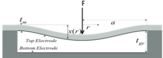
A cross sectional view of a circular airborne CMUT and its important parameters are shown in Figure 1, where a is the diameter of the CMUT, tge is the effective gap height, ti is the insulating layer thickness, and tm is the membrane thickness, F
is the total force exerted on the membrane. Acoustic wave is generated by applying an electrical signal between the electrodes of CMUT.
Fig. 1. Cross sectional view of circular airborne CMUT.
We use an accurate lumped element model [2] of CMUT, shown in Figure 2. It is assumed that the membrane is rigidly clamped and there is no loss of energy to the substrate in this equivalent circuit model. The left side models the electrical section and the right hand side models the mechanical section.
Lm is determined by the mass of the CMUT plate and Cm is the compliance of the plate. In the rms equivalent circuit,
3 0 2 2
16
)
1
(
5
9
m Rm mC
Y
t
a
C
π
σ
−
=
=
(1)where Y0 is the Young’s modulus and σ is the Poisson ratio of silicon.
The mechanical resonance frequency of CMUT can be calculated in terms of mechanical section elements as
1
L
RmC
Rm , wherem Rm
m
L
a
t
L
=
=
ρπ
2 (2)This expression yields the following relation at the resonance frequency:
(
)
0 2 080
9
1
)
(
Y
c
a
k
a
t
m r m=
−
σ
ρ
(3) 1416978-1-4673-5686-2/13/$31.00 ©2013 IEEE 2013 Joint UFFC, EFTF and PFM Symposium
where kr is the wavenumber at resonance, ρm is the density of
silicon, c0 is the speed of sound in medium. The quality factor,
Qm, of the mechanical side is
)
(
)
(
a
k
R
a
k
X
L
Q
r R r R Rm r m+
=
ω
(4)where ωr=2πf is resonance frequency of the mechanical part, XR(ka)=πa2ρ0c0X1(ka) is the radiation reactance and
RR(ka)=πa2ρ0c0R1(ka) is the radiation resistance in air. The density of air is ρ0.
To achieve a low quality factor at the given frequency with a given radius of CMUT, (4) shows LRm must be made smaller (in air XR and RR are very small compared to ωrLRm). To keep the resonance frequency the same, the membrane must be made either from a stiffer or a lighter material. A low LRm value means a low tm value and using low tm is similar to using stiffer material.
Fig. 2. CMUT’s equivalent circuit model.
Mechanical quality factor, Qm, can be written in terms of material properties as ) ( ) ( ) ( 1 1 0 1 R k a a k X a t a k R a k Q r r m m r r m = ρ + ρ (5)
where ρm/ρ0 is the membrane-to-air density ratio.
Equation (5) shows that a low quality factor can be achieved by increasing a/tm ratio. We note that the density ratio is about 2000 for a silicon membrane operating in air.
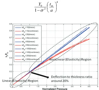
The atmospheric pressure depresses CMUT top plate towards the bottom electrode. Operation of a CMUT cell can be described using a linear mechanical model if the deflection is small. It is commonly accepted in literature that under 20% of deflection to thickness ratio [3], a membrane can be analyzed as a linear element in terms of elasticity and above this point it is analyzed as a nonlinear element. Hence we assume that the dependence of pressure and deflection is linear if the center deflection, XP, is less than approximately 0.2 of membrane thickness [3-4]. However, as the deflection is increased beyond this point, nonlinear effects become significant (Fig. 3). In this figure, the dependency of deflection to thickness ratio, XP/tm, with respect to normalized pressure is depicted and the pressure is normalized by
4 2 0 1 − a t Y m σ (6)
Fig. 3. Deflection to thickness ratio versus normalize pressure for different a/tm ratios.
Fig. 3 is the result of finite element analysis (FEA) for different a/tm ratios. In FEA, the nonlinear effects can be observed by considering stress stiffening effect. We generated this plot considering with and without stress stiffening effect. The difference between the linear and nonlinear regions becomes significant beyond a deflection to thickness ratio of 20%. On the other hand, a/tm ratios are varied from 10 to 200, deflection is not significantly different in both linear and nonlinear regions.
In Fig. 4, ka and a/tm at the mechanical resonance frequency are plotted with respect to Qm using Eqs. (3) and (5). For example, to achieve a Qm of 120 one needs a membrane with
a/tm ratio of 75 and ka equal to 0.9.
Fig. 4 shows that minimum Qm achievable with a single cell using single crystal silicon membrane is about 109 when stiffening effect is disregarded. At this optimum ka=0.45 and
a/tm=150. On the other hand, for such high a/tm ratios, the deflection due to atmospheric pressure is large, hence the stiffening effect is significant and it cannot be ignored.
Fig. 4. ka and a/tm at the resonance frequency as a function of the
mechanical quality factor for a silicon membrane in air. (Stiffening effect is ignored)
III. MODELING THE STIFFENING EFFECT OF CMUT PLATE As a/tm is increased membrane becomes more compliant. The center deflection-to-thickness ratio may exceed 0.2 due to the atmospheric pressure. The stiffness of the membrane increases and resonance frequency shifts upward. As a result, a relatively thin membrane may act like a high stiffness material when it is deflected beyond its linear operation limits.
Downward shift in resonance frequency due to increase in
a/tm ratio can be compensated by the increased stiffness of the membrane. Therefore, higher a/tm ratios, hence lighter membranes are possible for the same resonance frequency. Designs in this range must consider the induced stress in the membrane.
Note that single crystal silicon is a very flexible material and its fracture stress is around 7000-9000MPa [5]. This excellent property makes silicon suitable to be used as a membrane material where the membrane is stiffened by static deflection.
The stress induced by deflection due to atmospheric pressure and DC bias is maximum at the periphery of the clamped membrane. Induced stress cannot be allowed to increase indefinitely because it causes material fatigue. In normal operation this maximum stress must be kept below a certain allowable level.
The average equivalent circuit is appropriate for static analysis [2] and the compliance in this circuit, Cm= CAm, is given as 3 0 2 2
16
)
1
(
m AmY
t
a
C
π
σ
−
=
(7)The compliance of the membrane deviates from its linear value as the membrane is stiffened. The variation of average compliance, CA, normalized to its unstiffened value, CAm, with respect to XP/tm is depicted in Fig. 5.
Fig. 5. The ratio of average compliance to its unstiffened value with respect to deflection to thickness ratio.
CA/CAm is obtained by FEA. a/tm is varied between 50 and 200 and a uniform pressure between 0 to 30 atmosphere. Variation of CA/CAm for different a/tm values are depicted in Fig. 5. It is important to note that approximately the same variation with respect to XP/tm is obtained at all a/tm values.
In order to avoid the singularity at the rim of clamped membrane in FEA, we used a radius of curvature as depicted in Fig. 6. We select the radius of the curvature to be 3 μm. The maximum stress developed at the periphery is affected by the choice of this radius. This is most observable at XP/tm=0. The difference is the largest for thick membrane and converges to one as a/tm increases.
Fig. 5 shows that more depression results in stiffer membrane. At XP/tm =4.6 the single crystal silicon membrane is 10 times stiffer than that of unstiffened membrane. At XP/tm
=7 and 9.8 the membrane is 20 times and 40 times stiffer than
the unstiffened membrane, respectively. A stiffer material is preferred, because it results a wider bandwidth. We choose a deflection-to-thickness ratio of XP/tm =4.6. as a compromise between wider bandwidth and increased risk of membrane failure.
Fig. 6. ka versus mechanical quality factor for different a/tm values.
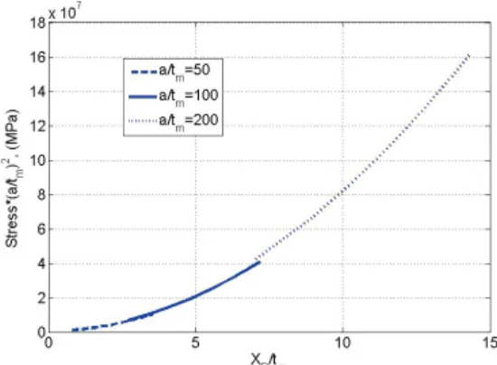
The induced stress at the rim of a thin membrane is proportional to the square of a/tm ratio. The stress is multiplied by (a/tm)2 and plotted with respect to XP/tm in Fig. 7 for
a/tm=50, 100 and 200. Multiplication by (a/tm)2 removes a/tm dependency. The scaled curves approximately overlap with each other for all a/tm ratios.
Fig. 7. CMUT stress levels versus deflection to thickness ratio for different a/tm values for a silicon membrane .
The figure shows that for XP/tm=4.6, Stress*(a/tm)2 is 1.8e7 Pa. For a/tm=150, the maximum stress due to atmospheric
pressure and DC bias is approximately 900 MPa at the periphery of the membrane. Note that this stress level is safe for fracture free operation when compared to reported fracture stress levels.
Ignoring the force term in the lumped element circuit model, the new resonance frequency is obtained as
2 2 20 2 0 2
)
(
1
)
1
(
16
1
)
(
0
+
−
=
A R Am A r r m m m m rx
x
C
C
a
k
a
k
X
t
a
a
t
Y
c
a
k
ρ
ρ
ρ
σ
(8)where xR and xA are the rms and average values of the displacement, respectively.
It can be easily shown that the actual depression for stiffened membrane becomes, g b Am A ge P
F
F
C
C
t
x =
(9)in the absence of bias voltage, where Fb is the external static force and Fg is the force required to deflect the center of the membrane by tge when the stiffening effect is ignored [2].
As an example, we use XP/tm=4.6 which makes CA/CAm=
0.1. Then we select a/tm=150 for 900 MPa maximum induced
stress. For these values kra is found as 1.6 from (8) and the
mechanical quality factor is found approximately as 37 at the resonance frequency (30 kHz). Because k is 554.4 in air at 30kHz, CMUT membrane radius and thickness of the membrane becomes 2.89 mm and 19.3μm, respectively.
If the center deflection of the membrane is allowed to be 0.7 of the effective gap height at 1 atm, the effective gap height, tge, can be found from (9) as 126 μm. If depression is allowed to be 0.9 of tge effective gap height is found as 98.5 μm.
IV. CONCLUSION
In this work, we propose a design procedure to significantly reduce the quality factor and calculate design parameters for minimum excitation voltage level for a specific frequency. Static depression and stiffened membrane compliance are used in the equivalent circuit model to design wide bandwidth airborne CMUT at the desired frequency. We found that the limit for mechanical quality factor is around 109 and a/tm ratio of 150, if the elasticity of the membrane is assumed unchanged. Such thin membranes are depressed significantly by atmospheric pressure so that the membrane becomes stiffer due to induced stress. We show that a lower quality factor level of around 40 can be achieved, by stiffening the single crystal silicon material.
ACKNOWLEDGMENT
This work is supported in part by Turkish Scientific and Research Council (TUBITAK) under project grants 110E216. AA thanks TUBA for the research support.
REFERENCES
[1] B. Bayram, "Diamond-based capacitive micromachined ultrasonic transducers," Diam. Relat. Mater., vol. 22, no. 2, pp. 6-11, Feb. 2012. [2] H. Koymen, et al., “An improved lumped element nonlinear circuit
model for a circular CMUT cell,” IEEE Trans. on Ultrason., Ferroelec. and Freq. Cont., vol. 59, no. 8, pp. 1791–1799, August 2012.
[3] E. Ventsel and T. Krauthammer, “Thin plates and shells,” 1st ed., New York: Marcel Dekker, Inc., 2001.
[4] Mario Kupnik, et al., “Finite element analysis of stress stiffening effects in CMUTs,”IEEE Ultrasonics Symp. 2008, pp. 487–490 October 2012. [5] Kurt E. Petersen, “Silicon as a Mechanical Material”, Proceedings of the
IEEE, vol. 70, NO. 5, pp. 420-454 1982.