Channel Estimation for Spatial Modulation
Orthogonal Frequency Division Multiplexing Systems
Yusuf Acar Hakan Dogan Erdal Panayrrcl
Department of Electrical and Electronics Engineering, Kadir Has University
34083, Cibali, Istanbul, Turkey. Department of Electrical and Electronics
Engineering, Istanbul Kiiltfu University 34156, Bakirkoy, Istanbul, Turkey
Email: [email protected]
Department of Electrical and Electronics Engineering, Istanbul University 34320, Avcilar, Istanbul, Turkey
Email: [email protected] Email: [email protected]
Abstract-A combination of spatial modulation and orthog onal frequency division multiplexing (SM-OFDM) has been recently proposed for multicarrier systems while assuming the perfect channel state information (P-CSI) available at the receiver. But, in practical scenarios, the estimation of CSI is crucial in order to detect the transmitted data coherently. In this work!, a new frame structure and pilot symbol aided channel estimation (PSA-CE) technique with a piecewise linear interpolation is proposed for the SM-OFDM systems operating in the presence of frequency selective channel. Bit error rate (BER) performance of the proposed channel estimation technique is then investigated with different channel models such as Typical Urban (TU) and Rural Urban (RU) for 4-quadrature amplitude modulation (QAM). In particular, it is shown that the performance with estimated channel came close to that with known channel within
2.3 dB in SNR for BER
=
10-4 for TU channels.Keywords-multiple-input multiple-output (MIMO), orthogonal frequency division multi- plexing (OFDM), spatial modulation
(SM), channel estimation, interpolation. I. INTRODUC TION
Multiple-antenna techniques is important technology for sending multiple data streams. However, in practices, multiple antenna techniques have some problems such as inter channel interference (lCI) and inter antenna synchronization (lAS) [1], [2]. Spatial modulation (SM) was proposed to overcome these problems by Mesleh et al. [3]. In SM system, the data symbols are transmitted by a randomly selected active antenna of a MIMO transmitter through a wireless channel. The SM is to use the indices of transmit antennas to convey information in addition to the two-dimensional signal constellations. Conse quently, the SM has a very flexible mechanism that provides high spectral efficiency with low complexity [4].
Orthogonal frequency division multiplexing (OFDM) tech nique has been widely accepted to meet the requirements of high data rate, reliability, capacity and mobility in practical wireless environments, due to its robustness to inter-symbol interference (lSI). Using cyclic prefix can convert frequency selective channel into multiple independent frequency flat subchannels [5]. However, the low bit error rates (BER) performances of OFDM must be improve by new techniques. Recently, SM and OFDM have been combined to take advantages to achieve reliable communication over wireless ! This work is supported in part by the Turkish Scientific and Technical Research Institute(TUBITAK) under Grant 114EOIl.
links [6]. It was shown that the SM scheme had significant performance advantages over the V-BLAST systems [6]. It has the advantages of both OFDM transmission and SM technique, and hence it is a potential modulation technique to be used for the next wireless communication systems.
In the literatre, the pioneering works on SM-OFDM works have assumed the perfect channel state information (P-CSI), available at the receiver. However, SM-OFDM communication requires channel estimation. It is clear that the nonselective assumption is not reasonable for frequency selective channels for SM-OFDM systems. The pilot symbols based channel estimators (PSA-CE) is one of the promising techniques for frequency selective channels. PSA-CE with interpolation techniques is widely used for new wireless systems, such as IEEE 802.16m worldwide interoperability for microwave access (WiMAX) [7], the third generation partnership project (3GPP) and long-term evolution (LTE) Advanced [8]. PSA-CE with several interpolation techniques based channel estimation for OFDM systems were proposed in [9]. It was shown that the piecewise linear interpolation is the frequently used interpolation techniques mainly due to its easy implementation and inherent simplicity.
In this work, pilot symbols are inserted systematically in the frequency domain to track the frequency selectivity of the channel. After that, a piecewise linear interpolation technique is employed to determine the channel frequency responses at data symbols. Note that, designing a PSA-CE with interpolation is quite different and challenging than the conventional PSA-CE techniques due to the special structure of the SM-OFDM systems. Because, in SM system there is only one active antenna during transmission so other channels could not be known at that time.
The paper is organized as follows. In Section II we discuss the SM-OFDM system model to introduce the notations. In Section III we develop 4 x 4 SM-OFDM with PSA-CE.
Simulation results are presented in Section IV Finally section V contains conclusions.
Notation: Throughout the paper, bold and capital letters 'A' denote matrices and bold and small letters 'a' denote vec tors. The notations,
(
.)
*,(.)T, (.)t
andII.IIF
denote conjugate,transpose, Hermitian and Frobenius norm, of a matrix or a vector respectively.
1st Antenna 2nd Antenna Mapping Antenna Modulation Bits Bits QPSK Constellation Points Mapping BPSK 1st Ant •• nna,." 2nd 3rd
Antenna Modulation Constellation
Bits Bits Points
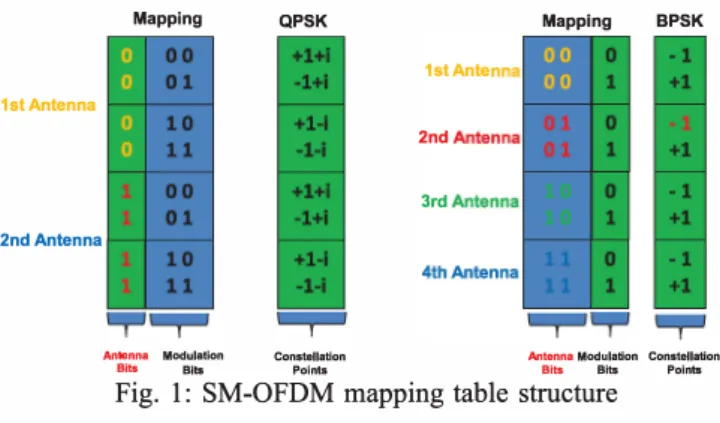
Fig. 1: SM-OFDM mapping table structure II. SPATIAL MODULATION-ORTHOGONAL FREQUENCY
DIVISION MULTIPLEXING (SM-OFDM) SYSTEMS Let B
( k)
be an b x N binary matrix, where b is the totalnumber bits per symbol per sub carrier (bits/symbollsubcarrier) and N is the total number of OFDM subcarriers. The data to be transmitted in one sub carrier is shown by the column vectors of
B(k).
By using the SM mapping table shown in Fig. 1. SM mapsB(k)
data bits into matrixX(k)
of size Nt x N, where Nt is the total number of transmit antennas. Allelements of
X(k)
is zero except at the position of the mapped transmit antenna indices. Thus, it has a one nonzero value in each column. Totally, three bits can be transmitted by BPSK and four transmit antennas on each subcarrier. Alternatively, quadrature phase shift keying modulation (QPSK) and two transmit antennas can be used to transmit the same number of information bits, as shown in Fig. 1. The number of bits that can be transmitted on each OFDM subchannel can be written as follows:(1) where M is modulation degree. Then, each row vector of
X(k)
is processed by an N-sample Inverse Fast FourierTransform (IFFT) operation. The N output samples of the IDFT is extended by a guard interval containing G sample cyclic extension whose length is selected to be longer than the expected channel delay spread to avoid the inter symbol interference (lSI). The resulting signal is converted into an analog signal by a digital-to-analog (D/A) converter. After pulse shaping with a raised-cosine filter, it is transmitted with the total symbol duration of
T
=PTs
whereTs
is the sampling period andP
= N + G. Finally, OFDM symbols at each transmit antennas are simultaneously transmitted from the Nt transmit antennas over the MIMO channel. At the receiver, after using the analog-to-digital converter(AID)
and deleting the cyclic prefix (CP), a fast Fourier transform (FFT) is applied eachNr
received antennas. The output the OFDM demodulators can be written for kth sub carrier as follows:YI
(k)
hI,I (k)
hI,2(k)
hI,N,
(k)
0
WI
(k)
h2,1
(k)
h2,2
(k)
h2,N,
(k)
o w
N
r(k)
(2) where
hr,j
(k)
is the channel coefficient between jth transmitter antenna and rth receiver antenna,Xq (k)
is the qth activeantenna symbol from the M-ary constellation diagram, w
r
(k)
is complex-valued, zero-mean white Gaussian noise (AWGN) with variance
u!.
The signal model (2) can be shown in matrix form as follows: where
y(k)
=H(k)xj(k)
+w(k), k
= 1,2,··· ,N.Xj(k)
� [0···
xq(k)
... OjT
--."...-j.
transmitted antenna (3)(4)
To detect the transmitted symbol and the transmit antenna number for each OFDM sub channel the optimum receiver which based on the maximum likelihood principle is used in the frequency domain. Optimal detector based on the maxi mum likelihood (ML) principle for a single OFDM subchannel given in as follows:
[JML' qML]
=argmaxpy(y(k)
I
xq(k), hj(k))
(5)k
],q
where
xq(k)
is qth symbols from M-QAM constellation andhj (k)
is jth row ofH( k)
. The probability density function (pdf) ofy( k)
conditioned onXq (k)
andhj (k)
can be written as:py(y(k) I Xq(k) , hj (k)) =
7[-Nr
exp(lly(k) - hj (k)xq (k)
II�)
(6) Using (6), optimal detector given in (5) can be expressed as[JML' qML]
=argmax Ilgjq(k)ll�
-2Re{yt(k)gjq(k)}
k
],q
(7) where
gjq(k)
is:gjq(k)
=hj(k)xq(k),
1::::: j ::::: Nt, 1::::: q::::: M. (8) If the receiver detects bothJML
andqML
correctly, they can be easily de-mapped and combined to get back to the transmitted bits. However, it is clear that the receiver needs to know the full CSI.III. CHANNEL ESTIMATION FOR THE OFDM-SM SYSTEM
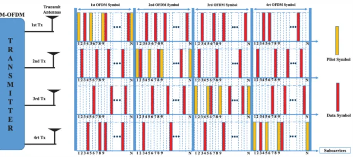
In practice, the SM-OFDM system, the channel state in formation (CSI) is needed to detect modulated symbols and indices of active transmit antenna number. The proposed frame structure of the 4 x 4 spatial modulated OFDM system is
illustrated in Fig. 2 where pilot symbols are active for different OFDM symbol durations. Therefore, MIMO channel could be estimated by active pilots for the corresponding durations. As shown in Fig. 2, to track the frequency variation of the channel, pilot symbols are inserted periodically over the subcarriers. As seen in Fig. 2 each transmit antenna transmit pilot symbols for the corresponding OFDM symbol number. For example, third transmit antenna sends pilot symbols for third OFDM symbol. PSA-CE with piecewise linear interpolation is a very popular and and frequently used interpolation techniques mainly due to its easy implementation and inherent simplicity [10]. However, the channel estimation with piecewise linear interpolation-based technique has not been investigated for the
Fig. 2: SM-OFDM frame structure
SM-OFDM systems in the literature yet. In this work, the channel frequency responses at pilots are estimated by the least square (LS) then channel parameters at the positions of data symbols are determined by the piecewise linear interpolation.
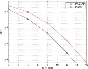
In Fig. 3, BER performance of the PSA-CE technique is shown for the RA channel models. It is not surprising to observe from our computer simulations results that in the presence of frequency selective channels, PSA-CE exhibited a 2.2 dB performance degradation in comparison to perfect CSI, due to the effect of CE errors for SM-OFDM systems. The linear piecewise interpoland can be simply expressed
for r = 1,2, ... , Nr and
kp
= 1 :PI R
:N
as follows:where
kp
is sub carrier position which pilot symbols transmit ted,hr,j(kp)
is estimated channel frequency responses at pilot positions andhr,j (k)
denotes the estimated channel frequency responses at all data positions.IV. SIMULATION RESULTS
In this section, we provide computer simulation results for the 4 x 4 SM-OFDM systems to demonstrate the BER perfor
mance of the proposed channel estimation with interpolation under frequency selective channel where the total transmitted power is normalized for the transmit antennas. The data sym bols are generated as uncorrelated symbols and the modulation format chosen uncoded 4-QAM signal constellation. The signal to noise ratio (SNR) is defined as
Es/No
whereEs
is energy per symbol andNo
is noise power. The optimum receiver is used for 4 x 4 SM-OFDM system.OFDM signal is generated within the 1 MHz band with
N
= 256 subcarriers. Each frame consists of 4 OFDM symbols. At the receiver, it is assumed that channel frequency response is estimated with all pilot based channel estimation for a fixed pilot insertion rate (PIR) of one every 8 data symbols. MIMO wireless channels between mobiles antennas and the receiver antennas are modeled based on Typical Urban (TU) and Rural Urban (RU) channel models proposed by the COST-259 project where the channel has the channel lengthL = 6 [11].
The effect of channel estimation on BER performance of the 4 x 4 SM-OFDM with TU channel models is presented in
Fig.
4.
It is noted that the performance with estimated channel came close to that with known channel within 2.3 dB in SNR at BER= 10-4. Moreover, error floor in BER for high SNR is not observed.As a result, the performance of the a piecewise linear interpolation, in case of frequency selective channel, indicates that it is a good candidate for a SM-OFDM system and it can be considered in the standards.
v. CONCLUSIONS
SM-OFDM is a recently developed transmission technique that uses multiple antennas. Therefore, the channel estimation plays a crucial role in the performance of SM-OFDM systems. In this work we proposed a channel estimation method based on interpolation in the presence of frequency selective channels for SM-OFDM systems. The algorithm is capable of estimat ing MIMO channel and there is no ambiguity in either the amplitude or the phase of the estimated channel. It has been shown that the PSA-CE with a piecewise linear interpolation technique is preferable estimation techniques because it allows tracking the frequency selectivity of the channel very effi ciently. The complexity of the channel estimation is extremely low. Therefore, it is concluded that the proposed technique is a candidate for next-generation practical SM-OFDM wireless standards.
Fig. 3: The BER performance of 4 x 4 4QAM-SM-OFDM with
channel estimation under RA channel models
c:: W III
Fig. 4: The BER performance of 4 x 4 4QAM-SM-OFDM with channel estimation under TU channel models
REFERENCES
[1] M. Chiani, M. Z. Win, and A. Zanella, "On the capacity of spatially correlated mimo rayleigh-fading channels," lriformation Theory, IEEE Transactions on, vol. 49, no. 10, pp. 2363-2371, 2003.
[2] D.-S. Shiu, G. J. Foschini, M. J. Gans, and J. M. Kahn, "Fading correlation and its effect on the capacity of multielement antenna systems," Communications. IEEE Transactions on, vol. 48, no. 3, pp.
502-513, 2000.
[3] R. Mesleh, H. Haas, C. W. Ahn, and S. Yun, "Spatial modulation a new low complexity spectral efficiency enhancing technique," in Communications and Networking in China, 2006. ChinaCom '06. First International Conference on. IEEE, 2006, pp. 1-5.
[4] M. D. Renzo, H. Haas, and P. M. Grant, "Spatial modulation for multiple-antenna wireless systems: a survey," Communications Mag azine, IEEE, vol. 49, no. 12, pp. 182-191, 2011.
[5] H. Dogan, E. PanaYlrcl, and H. V. Poor, "Low-complexity joint data de tection and channel equalisation for highly mobile orthogonal frequency division multiplexing systems," lET communications, vol. 4, no. 8, pp.
1000--1011, 2010.
[6] R. Y. Mesleh, H. Haas, S. Sinanovic, C. W. Ahn, and S. Yun, "Spatial modulation," Vehicular Technology, IEEE Transactions on, vol. 57,
no. 4, pp. 2228-2241, 2008.
[7] J. G. Andrews, A. Ghosh, and R. Muhamed, Fundamentals of WiMAX: understanding broadband wireless networking. Pearson Education,
2007.
[8] E. Dahlman, S. Parkvall, and J. Skold, 4G: LTEILTE-advanced for mobile broadband. Academic press, 2013.
[9] S. Coleri, M. Ergen, A. Puri, and A. Bahai, "Channel estimation techniques based on pilot arrangement in ofdm systems," Broadcasting, IEEE Transactions on, vol. 48, no. 3, pp. 223-229, 2002.
[10] S. Colieri, M. Ergen, A. Puri, and A. Bahai, "A study of channel estimation in ofdm systems," in Vehicular Technology Conference, 2002. Proceedings. VTC 2002-Fall. 2002 IEEE 56th, vol. 2. IEEE, 2002,
pp. 894-898.