Pilot Symbol Assisted Channel Estimation for 4x4
Space Time Block Coded Spatial Modulation
Systems
Yusuf Acar Hakan Dogan Erda! PanaYlrcl
Department of Electrical and Electronics Engineering, Kadir Has University
34083, Cibali, Istanbul, Turkey. Department of Electronics Engineering
Istanbul Kiiltiir University 34156, Bakirkoy, Istanbul, Turkey
Email: [email protected]
Department of Electrical and Electronics Engineering, Istanbul University 34320, Avcilar, Istanbul, Turkey
Email: [email protected] Email: [email protected]
Abstract-Recently, spatial modulation (SM) and space-time
block coding (STBC) are combined to take advantage of the benefits of both while avoiding their drawbacks for multiple-input and multiple-output (MIMO) systems. The pioneering works on STBC-SM assume that perfect knowledge of the channel fading coefficients is available at the receiver. This workl addresses the challenging and timely problem of channel estimation for 4 x 4
STBC-SM systems in the presence of time-varying channels. In this paper, the estimation of channel at pilot durations is done by least square (LS) method and then the channel interpolation is performed by linear interpolation or nearest neighbor inter polation algorithms. Simulation results have demonstrated that the proposed channel estimation based on the linear interpolation offer substantial performance gains over the channel estimation based on the nearest neighbor interpolation. In particular, a savings of about 5dB is obtained at BER = 10-5, as compared
with the nearest interpolation based receiver at 120km
/
h for 4 x 4STBC-SM systems with the binary phase shift keying (BPSK) modulation.
Keywords-Spatial Modulation; Space-Time Block Coding; Pi lot Symbol Assisted Channel Estimation; Multiple-Input Multiple Output; Time Varying Channels.
I. INTRODUCTION
The inter channel interference (lCI) and inter antenna synchronization (lAS) are traditional problems associated with practical multiple-input and multiple-output (MIMO) systems [1], [2]. Spatial modulation (SM) was proposed by Mesleh et al. [3] to overcome these problems associated with the conventional MIMO transmission schemes. The basic principle of the SM is to use the indices of transmit antennas to convey information in addition to the two-dimensional signal constellations. Hence, it adds a third dimension to the two dimensional signal space to obtain three-dimensional signal space.
Space-time block code (STBC) is proposed by Alamouti [4] to increase the coding gain or diversity gain for MIMO systems. Recently, a new MIMO transmission scheme, called STBC-SM, is proposed by Basar et al. [5]. STBC-SM takes
1 This work is supported in part by the Turkish Scientific and Technical Research Institute (TUBITAK) under Grant 114EOll and the Research Fund of Istanbul University under Projects Numbers: 44182 and 45861. This work is also supported by the 7th Frame European WIMAGIC Project. 978-1-4673-7788-1/15/$31.00 ©2015 IEEE
advantage of the benefits of STBC and SM while avoiding their drawbacks for MIMO systems. In the SM system, only one transmit antenna is active during each transmission interval, whereas STBC-SM uses the indices of the two transmit an tennas employed for the transmission of the Alamouti-STBC. Therefore the transmitted information symbols are included not only to the space and time domains but also to the spatial (antenna) domain in STBC-SM scheme. In this manner both antenna indices and STBC carry information. It was shown that the STBC-SM scheme has significant performance advantages over the SM systems. It also provides high spectral efficiency with the low computational complexity due to low-complexity maximum likelihood (ML) decoder which profits from the orthogonality of the Alamouti code [5].
In literature, the pioneering works have assumed that STBC-SM has perfect channel state information (P-CSI) at the receiver. However, reliable coherent STBC-SM communication requires accurate estimation of the fading channel. It is clear that the quasi-static fading assumption is not reasonable for time-varying channels for spatial modulated systems [6]. One of the main challenges faced by high mobility communications is the fast time-varying fading caused by the Doppler effect [7]. Therefore, a very popular and widely accepted method to deal with the system design for fast time-varying fading is pilot-symbol-aided channel estimation (PSA-CE) with using interpolation [8]. In this paper, we assumed that channel changes rapidly for consecutive time slots and we propose PSA-CE for STBC-SM systems in such situations. Therefore we investigate nearest and linear interpolation techniques in PSA-CE for
4
x4
STBC-SM systems. Finally, the PSA-CE methods have demonstrated their simplicity, effectiveness as well as efficiency.Notation: Throughout the paper, bold and capital letters 'A' denote matrices and bold and small letters 'a' denote vec tors. The notations,
(
.)
*,(
.) T, (
.)
t
and11.11
F denote conjugate,transpose, Hermitian and Frobenius norm, of a matrix or a vector respectively.
II.
4
x4
SPACE-TIME BLOCK CODED SPATIALMODUL ATION
(4
x4
STBC-SM)Let us consider an Alamouti
4
x4
STBC-SM system. In Alamouti's STBC, two complex information symbols(
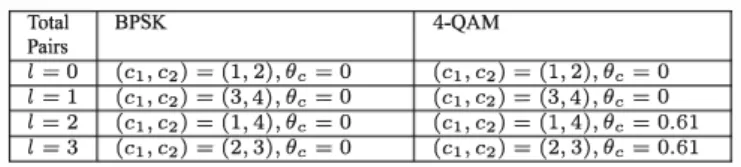
XlTABLE I: Alamouti STBC-SM scheme's parameters with four transmit antennas and different modulation type
Total BPSK
4-QAM
Pairs1-0 (Cl,C2) -(1,2),go -0
(Cl, C2) -(1,2), go -0
1-1 (Cl, C2) -(3,4), go -0
(Cl, C2) -(3,4), go -0
1
=2 (Cl, C2)
=(1,4), go
=0
(Cl, C2)
=(1,4), go
=0.61
1-3 (Cl, C2) -(2,3), go -0
(Cl, C2) -(2,3), go -0.61
and
X2)
drawn from an M-PSK or M-QAM constellation aretransmitted from two transmit antennas in two symbol intervals in an orthogonal manner by the codeword
X2)
=(
X\ xX;
)
- X2
1
(1)where columns and rows correspond to the transmit antennas and the symbol intervals, respectively.
For the STBC-SM scheme we extend the matrix in (1) to the antenna domain consisting of four transmit antennas in such a way that both STBC symbols and the indices of the transmit antennas from which these symbols are transmitted, carry information, as follows. Fist a pair of transmit antennas
C
=(Cl' C2)
E{I, 2, 3,4},
(Cl i-C2)
with a label £ E{I, 2, .. }
is chosen. Note that the total number of possible pairs, C, in such configuration isC
= 6 and a maximum2
bits per label can be transmitted by selecting any of the 4 possible antenna pair combinations. As to which combinations should be chosen is an another design problem and we do not consider it here. In our work,on the other hand, the four pairs and their labels are chosen according to the configuration considered in [5], as follows:£=
1
{:}C
=( 1, 2),
£=2
{:}C
=(3,4),
£=3
{:}C
=(1,4),
£=4
{:}C
=(2,3).
Consequently, the following four codewords can be gen erated by the suggested
4
x4
Alamouti STBC-SM scheme, arranged in two groups:{
Xll,X12
}
={ (
- X2 xi
Xl X2
0 0) (0 0
Xl X2
)}
00 ' 00
- X2 xi
{
X2l, X22
}
={ (0
Xl X2
0) (
X2
0 0
Xl
)}
jg
0
- X2 xi
0
' xi
0 0
- X2
e(2)
where the two STBC-SM codewords
Xij,
j =1,
2 in each groups above do not interfere to each other, satisfyingXij XtI,
=O2
x2
,ji- k;
that is they have no overlapping columns. In(2), e
is a rotation angle to be optimized for a given modulation format to ensure maximum diversity and coding gain at the expense of expansion of the signal constellation. In Table 1, the parameters £,C
=(Cl' C2)
and the optimal rotation anglese
are given for the codewords of(2)
and for binary phase-shift keying (BPSK) and quadrature phase shift keying (QPSK) modulation formats.We now formulate the ML decoder for the STBC-SM scheme. Due to the orthogonality of Alamouti's STBC scheme, we can expressed the received signals obtained at the output of
each receive antenna r =
1,
2, 3
,4
in two consecutive discrete time intervals nandn + 1
as follows.Yr (n)
=hr,Cl (n )'lj;cXl (n )+hr,C2 (n )'lj;cX2 (n )+Wr (n)
Yr(n + 1)
=- hr,ct (n + 1)'lj;cx;(n) + hr,C2(n + 1)'lj;cxi(n)
+wr(n + 1),
(3) where'lj;c
£ ejgo
andWr (n)
is complex-valued, zero-meanadditive white Gaussian noise (AWGN) with variance
O"�.
Under the assumption that the varying Rayleigh distributed channel coefficients between jth transmitter antenna and rth receiver antenna do not change along these intervals, that ishr,j(n + 1)
�hr,j(n),
the following equivalent observationmodel can be obtained from (3) and for £ {:}
C
=(Cl' C2)
in a vector form:y(n)
= diag( 1Pl)He
[�����]
+ w(n)
(4)where
He(n)
[hell £(n) h
�
2)(n)l.
and1Pl
['lj;c, 'lj;�, 'lj;c, 'lj;�, 'lj;c, 'lj;�, 'lj;c, 'lj;�lT
Generally, we have
C
equivalent channel matricesHe,
0 ::; £ ::; C -1, and for the £th combination, the receiver determines the ML estimates ofXl
andX2
resulting from the orthogonality ofh
�
l)(n)
andh
�
2)(n):
xl,£(n)
=arg��n
Il
y(n) -
diag( 1Pl)h
�
l)(n) xl
l1
2
x2,e(n)
=arg��n
Il
y(n) -
diag( 1Pl)h
�
2)(n) X2
11
2
(5)Associated minimum ML metrics
ml,£(n)
andm2,£(n)
forXl
andX2
areml,e(n)
=��n
Il
y(n) -
diag( 1Pl)h
�
l)(n) Xl
l1
2
m2,e(n)
=��n
Il
y(n) -
diag( 1Pl)h
�
2)(n) X2
11
2,
(6)respectively. Since
ml,£(n)
andm2,e(n)
are calculated by the ML decoder for the £th combination, their summationm e(n)
=ml,e(n) + m2,e(n),
0
::; £ ::;C
-1
gives the total ML metric for the £th combination. Finally, the receiver makes a decision by choosing ilie minimum antenna combination metric as€(n)
=arg min
mc(n)
for which(xl(n),x2(n))
=e
(Xl Z{n), X2 z{n)).
As a result, the total number of ML metric calculationIS 2C
M, yielding a linear decoding complexity.III. CHANNEL ESTIMATION FOR THE
4
x4
STBC-SM SYSTEM
In the
4
x4
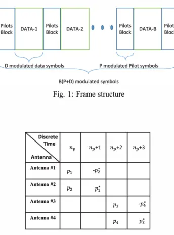
STBC-SM system, the channel state in formation (CSI) is needed to detect modulated symbols,Fig_ I: Frame structure
�
Time 17>+2 17> 17>+1 17>+3 Antenna Antenna #1 -Pz Pl Antenna #2 pi P2 Antenna #3 -P4 P3 Antenna #4 P3 P4Fig_
2:
Pilots block structure, Pi, i symbols1
,2
,3
,4
denotes pilot(Xl (n),
X2 (n) ,
and transmit antenna pair number,l(
n).
In practice, wireless systems encounter with the time-varying channel caused by the mobility. It is clear that the perfor mance of conventional channel estimation based on quasi static channel assumption will be degraded over the time varying channels. Therefore, PSA-CE with interpolation is used for the proposed receiver structure under high-speed mobile communication environments. Fig. I shows the frame structure for the4
x4
STBC-SM systems. Pilot symbols aretransmitted as shown in Fig.
2.
In this work, the interpolator of proposed channel estimation method is obtained by the linear or nearest interpolation methods. Assuming that fading is constant across two consecutive symbols, we can write the observation model as follows:Yl(n)
Y2(n)
Y3(n)
Y4(n)
Yl(n + 1)
Y2(n + 1)
Y3(n + 1)
Y4(n + 1
'---v--- yen)hl,cl(n)
h2,C, (n)
h3,Cl (n)
h4,Cl (n)
hl,c2(n)
h2,C2(n)
h3,C2 (n)
h4,C2(n)
'---v---' Hen)Wl(n)
w2(n)
w3(n)
w4(n)
+ wl(n + 1)
w2(n + 1)
w3(n + 1)
w4(n + 1)
'---v---- Wen) (7)where
Xl
andX2
are defined as follows:[
xl(n)
0 0 01
oXl (n)
0 07/J
Xl
= 0 0Xl(n)
0C
o 0 0Xl(n)
[
X2(n)
0 0 01
X
2
-- 0 0X2 (n)
0X2(n)
0 0 0 0/''l' c
o 0 0x2(n)
The received signal can be writing more succinct form as follows:
Y(n)
=X1-l(n) + W(n)
(8) The least square (LS) solution of observation model by the known transmitted pilot symbols, (8), can be written as,1-l(n)
=(xtX)-lXtY(n)
(9) where(xt X)-l
=2l
i
I, Eav is average symbol energy and I is identity matrix. avOne promising technique for time-varying Rayleigh fading channel is PSA-CE, because this method makes dynamic estimation for such channels. PSA-CE inserts known pilot symbols periodically in the time domain to track the time variation of the channel. Firstly, the received pilot blocks are operated with the known pilot blocks (by LS method given in (9» for estimating the channel impulse responses (CIRs) on all pilot positions. The PSA-CE with interpolation widely used in new generation wireless communication systems. After the LS estimation, the estimated CIRs on all data positions are calculated by the linear or nearest interpolations. The linear and nearest channel interpolation algorithms are discussed in the following subsections.
A.
Piecewise Linear Interpolation
It was shown that especially linear interpolation techniques are preferable due to their inherent simplicity and easy to implement [9] for pilot assisted channel estimation by means of interpolation techniques. However, the channel estimation with linear interpolation-based techniques and their performance analysis have not been investigated for the STBC-SM systems in the literature yet. In this work, time-varying, Rayleigh distributed channel coefficients are estimated by the one dimensional linear interpolation technique in a frame structure, consisting of periodically inserted pilot blocks and the data blocks with certain lengths each. The linear piecewise inter poland can be expressed for r =
1
,2,3
,4
and P =1,2""
,P as follows.hr,j(n)
=hr,j (np) +
(1/,
r,j (np+l) -hr,j(np)
)
x(
n -np
)
, for j =1,2; np ::::; n ::::; np+l
np+l -np
hr,j(n)
=hr,j(np + 2)+
(
hr,j(np+l + 2) - hr,j(np + 2)
)
x(
n -(np + 2)
)
, for j =3,4; np +2::::; n ::::; np+l +2,
np+l -np
(10)
where
hr,j(np)
is estimated CIRs at pilot durations,hr,j(n)
is estimated CIRs at all data positions and P is the total numberof pilot symbols by which the LS channel coefficient estimates are obtained. The
np
andnp
+2
are the discrete times at whichthe pilot symbols located and usually called breakpoints. 10-1 B.
Nearest Interpolation (Zero-Order Hold)
The nearest-neighbor interpolation technique interpolates between sample points by holding each sample value until the next sampling instant. In [9], it is shown that the per formance of linear interpolation is better than the nearest neighbor interpolation. The zero-order hold interpolator firstly inserts
(V
-1)
zeros between successive samples of channelcoefficients,
hr,j(np),
as follows:h
r,]
.(n)
={
hr,j(np)
p =1
:. P0
otherwIse (11
)where
V
= P + D is the frame length. The interpolated channel sampleshr,j (n)
are obtained by convolving a zero-ord�r hold interpolation pulse shape with the intermediate signal,hr,j (n)
as: 00hr,j(n)
=L
h(n -np)hr,j(np)
(12)
np=-oo whereh( )
n
={
0
1 0 ::; n
otherwise < Ts(13)
Duration of the rectangular pulse is exactly equal to the sampling period.IV. SIMUL ATION RESULTS
In this section, simulation results are presented to vali date the proposed PSA-CE with interpolation method for the
4
x4
STBC-SM systems.4
x4
STBC-SM block consists of P + D =104
samples P =4
of which constitutes the pilot symbols. Totally, B =10
block are transmitted in a frame. The signal to noise ratio (SNR) is defined as�
where Es is the energy per symbol andu2
is the noise power. The channel between transmitter and receiver is modeled as a time-varying Rayleigh fading channel having a Doppler shift determined by the terminal velocity and the carrier frequency chosen in the simulations. In our computer simulations, ilie mobile terminal is assumed to be moving with1 20
kmJh for a carrier frequency of1.8
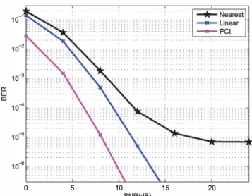
GHz and the symbol duration Ts = lOf-ts.The effect of channel estimation on BER performance of the
4
x4
STBC-SM with BPSK scheme is presented in Fig.3.
The results are shown for linear interpolation and nearest interpolation cases assuming we have perfect channel state information (P-CSI). It is observed iliat the linear interpolation exhibits about 5 dB detection gain over nearest interpolation at BER=10-5
and the difference in BER performance between linear and nearest interpolation increases toward high SNR values. Moreover, the nearest interpolation method yields an error floor at high SNRs.The results in Fig. 4 show that, with QPSK signaling employed, the linear interpolation technique outperforms the nearest interpolation. In particular, it is observed that a 5 dB gain is achieved at BER=
10-4,
as compared with the nearest interpolation technique. It also is demonstrated that the nearest interpolation has irreducible error floors at0:: W In
o 5 10 15
SNR(d8) 20
Fig.
3:
The BER performance of4
x4
BPSK-STBC-SM with channel estimation atV
=1 20km/h
0:: W In o 5 10 15 SNR(d8) 20Fig. 4: The BER performance of
4
x4
QPSK-STBC-SM with channel estimation atV
=1 20km/h
high SNRs. Consequently, it is not surprising to see from the computer simulations that, the performance of nearest interpolation technique degrades especially at higher SNRs mainly due to the effect of the rapidly varying channel. Thus linear interpolation is preferable mainly due to its superior performance and easy implementation achieved by low computational complexity.
V. CONCLUSIONS
The STBC-SM systems is one of the promising techniques for the next generation wireless communication systems and solving the channel estimation problem is of great interest in
design and implementation of these systems. In this paper, we showed that the presence of channel estimation errors inevitably results in a performance degradation for STBC-SM systems and proposed a PSA-CE technique with linear inter polation to track the variations in time-domain over the time varying Rayleigh fading channel. Linear interpolation based PSA-CE scheme was shown to be superior BER performance over the PSA-CE with the nearest interpolation technique, for a
4
x4
STBC-SM system. The computer simulations indicated that the PSA-CE with nearest interpolation technique has an irreducible error floor at higher SNRs. As a conclusion, the PSA-CE scheme with linear interpolation is preferable mainly due to its performance and feasible implementation.REFERENCES
[1] D.-S. Shiu, G. J. Foschini, M. J. GallS, and J. M. Kahn, "Fading corre lation and its effect on the capacity of multielement antenna systems,"
Communications, IEEE Transactions on, vol. 48, no. 3, pp. 502-513, 2000.
[2] M. Chiani, M. Z. Win, and A. Zanella, "On the capacity of spatially correlated MIMO rayleigh-fading channels," Information Theory, IEEE Transactions on, vol. 49, no. 10, pp. 2363-2371, 2003.
[3] R. Mesleh, H. Haas, C. W. Ahn, and S. Yun, "Spatial modulation a new low complexity spectral efficiency enhancing technique," in
Communications and Networking in China, 2006. China Com '06. First International Conference on. IEEE, 2006, pp. 1-5.
[4] S. Alamouti, "A simple transmit diversity technique for wireless commu nications," Selected Areas in Communications, IEEE Journal on, vol. 16, no. 8, pp. 1451-1458, Oct 1998.
[5] E. Basar, U. Aygolu, E. Panayirci, and H. V. Poor, "Space-time block coded spatial modulation," Communications, IEEE Transactions on,
vol. 59, no. 3, pp. 823-832, 2011.
[6] S. Sugiura and L. Hanzo, "Effects of channel estimation on spatial modulation," Signal Processing Letters, IEEE, vol. 19, no. 12, pp. 805-808, 2012.
[7] J. K. Cavers, "An analysis of pilot symbol assisted modulation for rayleigh fading channels [mobile radio]," Vehicular Technology, IEEE Transactions on, vol. 40, no. 4, pp. 686-693, 1991.
[8] S. Coleri, M. Ergen, A. Puri, and A. Bahai, "Channel estimation techniques based on pilot arrangement in ofdm systems," Broadcasting, IEEE Transactions on, vol. 48, no. 3, pp. 223-229, 2002.
[9] J. Rinne and M. Renfors, "Pilot spacing in orthogonal frequency division multiplexing systems on practical channels," Consumer Electronics, IEEE Transactions on, vol. 42, no. 4, pp. 959-962, 1996.