Quarter Wave Fresnel Rhomb with Colinear Output Beam
A. Serpenguzel, Dept. of Physics, Bilkent Univ., Bilkent, Ankara, Turkey. Abstract
A standard quarter wave (λ/4) Fresnel rhomb laterally dis places the output beam with respect to the input beam. This lateral displacement can cause problems when inserting the rhomb in an already aligned optical setup. This note describes the use of two λ/8 rhombs to construct a λ/4 rhomb. The output of the proposed rhomb is colinear with the input beam, and allows a much more flexible optical alignment.
Introduction
Achromatic quarter wave (λ/4) or half wave (λ/2) retarders are manufactured using Fresnel rhombs.1 The standard λ/4 rhomb creates a phase shift (δ) of 90° between the parallel (//) and the perpendicular (_L) components of an incident polarized beam upon total internal reflection (TIR). If prop erly aligned, it can convert a linearly polarized beam to a cir cularly polarized beam and vice versa. The output of the λ/4 rhomb is displaced laterally with respect to the input beam. This lateral displacement causes alignment problems, when inserting the rhomb in an already aligned optical setup.
The standard λ/2 rhomb creates a phase shift (δ) of 180° between the // and _L components of an incident polarized beam. If properly aligned, it can rotate a linearly polarized beam by 90°. The standard λ/2 rhomb is com posed of two λ/4 rhombs. The output of the λ/2 rhomb is colinear with the input beam, making the optical alignment much more flexible.
This note proposes a λ/8 Fresnel rhomb that creates a phase shift (δ) of 45° between the // and _L components of an incident polarized beam. The proposed λ/4 Fresnel rhomb is composed of two λ/8 rhombs. The output of the proposed λ/4 rhomb is colinear with the input beam, mak ing the optical alignment much more flexible.
Calculation of the phase shift
The working principle of the Fresnel rhomb is based on the phase shift between the // and _L components of an inci dent polarized beam upon TIR. This phase shift can be cal culated using
where 6^ is the angle of incidence and n is the refractive index of the rhomb.
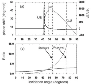
Figure 1 . (a) Calculated phase shift (thin line) and its derivative
(thick line) as a function of the incidence angle for a glass rhomb
(n= 1.51). (b) Calculated L/A (thin line) and H/A (thick line) ratios
as a function of the incidence angle.
engineering & laboratory notes 7156
Figure 2. (a) Optical schematic of the (a) standard λ / 4 , (b) stan
dard λ / 2 , and (c) unrealized λ / 4 rhombs.
Figure la (previous page) shows the phase shift, δ, between the // and ┴ polarized waves as a function of the incidence angle for glass (n = 1.51) calculated using Eq. 1. Figure la also shows the first derivative of δ with respect to the incidence angle (dδ/dθi) to estimate the variation of δ for small angular misalignments, with larger variations cor responding to smaller angular tolerances.
Calculation of the physical dimensions
Figure lb shows the length/aperture (L/A) and the height/aper ture (H/A) ratios of a double rhomb calculated using
The standard λ / 4 and λ / 2 rhombs
As indicated by the dotted lines labeled λ/4 in Figure la, a phase shift of λ = 45° occurs for both (θi) = 48°37' (with dδ/dθi = 53) and θi = 54°37' (with dδ/d0. = -27). Since the
angular tolerance of θi = 54°37' is higher than θi = 48°37',
the standard λ/4 rhomb uses two δ = 45° TIR at θi = 54°37'. The standard λ/4 rhomb is shown in Figure 2a. The rhomb angle is equal to the incidence angle of θi = 54°37'. The out put beam is displaced laterally, parallel to the input beam. As mentioned previously, this lateral displacement creates difficulties in optical alignment. For a standard λ/4 rhomb, a typical aperture size of 1 cm requires a length of 1.85 cm
Figure 3. (a) Optical schematic of the (a) proposed λ / 8 , (b) proposed λ / 4 , and (c) unex
plored λ / 8 rhombs.
and a height of 2.3 cm, as indicated by the dotted "standard" line at θi = 54°37' (Fig. lb).
Figure 2c describes the steeper λ/4 rhomb with θi = 48°37', a typical aperture of 1 cm, shorter length of 1.3 cm, and height of 2.1 cm, which would fit into a crowded system easier. But since the angular tolerance of θi = 48°37' (with dδ/dθi = 53) is smaller than θi. = 54°37' (with dδ/dθi. = -27), the θi = 48°37' configuration is not realized.
The standard λ/2 rhomb is shown in Figure 2b and is composed of two λ/4 rhombs. Four reflections within a pair of λ/4 rhombs produces a λ/2 retarder. The output beam is colinear with the input beam, and the optical alignment is very flexible. For a standard λ/2 rhomb, a typical aperture size of 1 cm requires a length of 3.7 cm and a height of 2.3 cm, as indicated by the dotted "standard" line at θi= 54°37' (see Fig. lb).
The proposed λ / 8 and λ / 4 rhombs
As indicated by the dashed lines labeled λ/8 in Figure la, a phase shift of δ = 22.5° occurs at θi = 42°20' (with dδ/dθi = 783) and θi = 74°42' (with dδ/dθi = -81). Since the angu lar tolerance of θi = 74°42' is higher than θi = 42°20', the proposed λ/8 rhomb uses two δ = 22.5° TIR at θi = 74°42' (see Fig. 3a). The rhomb angle is equal to the incidence angle of θi = 74°42'. The output beam is displaced laterally, parallel to the input beam. For the proposed λ/8 rhomb, a typical aperture size of 1 cm requires a length of 6.8 cm and a height of 2.9 cm, as indicated by the dashed "proposed" line at θi = 74°42' (see Fig. lb).
Figure 3c describes the steeper λ/8 rhomb with θi = 42°20', a typical aperture of 1 cm, shorter length of 0.8 cm, and a height of 1.9 cm, which would fit into a crowded system easier. But since the angular tolerance of the θi = 42°20' (with dδ/dθi = 783) is smaller than the angu lar tolerance of 0. = 74°42' (with dδ/dθi = -81), the 0. = 42°20' configuration is not explored. Also since 42°20' is smaller than 45°, the θi = 42°20' configuration allows the transmission of direct rays as indicated in Figure 3c.
The proposed λ/4 rhomb is shown in Figure 3b and is composed of two λ/8 rhombs. The output beam is colinear with the input beam (similar to the case of the standard λ/2 rhomb) making optical alignment very flexible. For the proposed λ/4 rhomb, a typical aperture size of 1 cm requires a length of 13.6 cm and a height of 2.9 cm, as indicated by the
dashed "proposed" line at θi = 74°42' (see Fig. lb). For the same aperture size the proposed λ/4 rhomb with colinear output beam has 7.4 times the length and 1.3x the height of the standard λ/4 rhomb. The angular tolerance of the proposed λ/4 rhomb (with dδ/dθi = -81) is only 3x lower than the standard λ/4 rhomb (with dδ/dθi = -27). Therefore, for applica tions where colinearity is an important factor, the proposed λ/4 rhomb is a good candidate for replacing the standard λ/4 rhomb.
References
1 . M. Born and E. Wolf, Principles of Optics (Pergamon Press, Oxford, U.K., 1987) p. 5 0 .