Numerical analysis and synthesis of 2D
quasi-optical reflectors and beam waveguides
based on an integral-equation approach
with Nystrom’s discretization
Andrey A. Nosich,1,*Yuriy V. Gandel,1Thore Magath,2and Ayhan Altintas3
1
School of Mathematics, Kharkiv National University, Kharkiv 61077, Ukraine
2
EuTC Research Communication, Panasonic Electronic Devices (Europe) GmbH, Zeppelinstrasse 19, 21337 Lueneburg, Germany
3
Department of Electrical and Electronics Engineering, Bilkent University, Ankara 06800, Turkey
*Corresponding author: [email protected]
Received December 8, 2006; revised April 26, 2007; accepted May 3, 2007; posted May 9, 2007 (Doc. ID 77895); published August 10, 2007
Considered is the beam wave guidance and scattering by 2D quasi-optical reflectors modeling the components of beam waveguides. The incident field is taken as the complex-source-point field to simulate a finite-width beam generated by a small-aperture source. A numerical solution is obtained from the coupled singular inte-gral equations (SIEs) for the surface currents on reflectors, discretized by using the recently introduced Nystrom-type quadrature formulas. This analysis is applied to study what effect the edge illumination has on the performance of a chain of confocal elliptic reflectors. We also develop a semianalytical approach for shaped reflector synthesis after a prescribed near-field pattern. Here a new point is the use of auxiliary SIEs of the same type as in the scattering analysis problem, however, for the gradient of the objective function. Sample results are presented for the synthesis of a reflector-type beam splitter. © 2007 Optical Society of America
OCIS codes: 140.0140, 140.3290, 140.3410, 140.5960, 230.5750, 140.4780.
1. INTRODUCTION
Diffractive metallic mirrors or reflectors are key elements that provide the phase correction necessary for manipula-tion of beams across a wide range of frequencies from op-tical to millimeter (mm) waves. Despite noticeable losses in the visible range, applications of diffractive optical mir-rors are numerous and include laser beam focusing, redi-rection, coupling, feedback, spectral filtering, wavelength-division multiplexing, and optical disk readout [1–3]. As material losses of good metals sharply decrease with fquency, beam waveguides formed by chains of metallic re-flectors have become even more attractive for low-loss guidance of the terahertz and mm waves since the 1960s [4–10]. Today reflector beam waveguides are used, e.g., in the heating of plasma in controlled nuclear fusion ma-chines with the mm waves generated by high-power gy-rotrons and as feed lines for mm-wave radio astronomy antennas [11–13].
Electromagnetic modeling of reflectors is usually done with geometrical and physical optics [14–16] including the recently developed powerful auxiliary-plane approach [17]. However, these methods are based on ray tracing and fail to fully characterize fine interaction effects and resonances. For more accurate modeling, rigorous meth-ods are necessary. Note also that the currently popular finite-difference time-domain commercial field solvers re-quire prohibitively large computer resources when ap-plied even to a single reflector larger than 10 wavelengths in size, in open domain. Therefore their use in parametric
analysis is painful, and in numerical optimization so far it is virtually impossible.
These facts suggest that economic and accurate full-wave analysis and synthesis of reflectors and beam waveguides is still in demand. A general way to build cor-responding numerical algorithms is to use an integral-equation (IE) approach. Here, the crucial point is the de-velopment of an efficient discrete model, i.e., a fast and convergent numerical algorithm having controlled accu-racy.
In optics, where metals are lossy and beams are well collimated, reflectors are usually simulated with surface-relief structures and dielectric boundary conditions (i.e., a demand for continuity of the tangential field components across the surface) [18–20]. Therefore IEs are actually coupled pairs of equations along infinite contours.
In contrast to optics, mm-wave and terahertz reflectors can be considered perfect electric conductors (PECs) be-cause of very high electron conductivity in this range. As electromagnetic wave beams are less collimated in this case, the edges of reflectors have to be accounted for prop-erly. Therefore quasi-optical reflectors are normally simu-lated with zero-thickness PEC screens that lead to SIEs for the electric currents induced on finite surfaces with sharp edges. Such IEs always have singular kernels and therefore must be discretized carefully, especially if the needed accuracy is finer than the first couple of digits. In the 1990s, the method of analytical regularization was de-veloped to convert IEs into Fredholm second-kind matrix
equations because of the explicit inversion of the static parts [21].
An alternative approach uses Nystrom-type discretiza-tion of SIEs and specific quadrature formulas for the com-putation of the matrix elements. In [22], we presented ba-sic ideas of such a discrete model based on the method of discrete singularities (MDS) and gave some examples of the accurate 2D analysis of curved reflector antennas. In parallel, a similar approach was developed recently in [23] for flat 2D strips and slots in a layered environment. Note that these works use different edge-corrected quadrature formulas, although both consider the whole reflector as an entire domain and improve the accuracy by increasing the order of interpolation polynomials, i.e., the reflector is not meshed with a finer and finer set of sub-domains.
In the sections that follow, we consider the E-polarized beam wave guidance and scattering by a chain of 2D quasi-optical reflectors used as a waveguide, and we study the role of the reflector edge illumination in the waveguide performance. We also develop a semianalytical approach for a shaped reflector synthesis after a pre-scribed near field pattern. Both analysis and synthesis use SIEs of the same type discretized with the aid of the MDS.
2. ANALYSIS AND MDS DISCRETIZATION
The geometry of a generic 2D reflector system, shown in Fig.1, is an example of a finite-length beam waveguide. The reflectors are assumed to be PEC and have zero thickness. The feed is a z-directed line current placed at the complex-valued source point (see also [21,22]) and has time dependence exp共−it兲, omitted in the analysis. The field generated by such a feed can be characterized by the z component of the electric field, which is given byU0共rជ兲 = H0共1兲共k兩rជ − rជc兩兲, 共1兲
where H0共1兲共·兲 is the Hankel function of the first kind, k =/c, rជc= rជ0+ ibជ, rជ0=共x0, y0兲, and bជ=共b cos,b sin 兲. The
Function(1)is a rigorous solution to the Helmholtz equa-tion and, because of the complex-valued argument,
simu-lates a directive beam looking within =. In the
paraxial domain, this is simply a Gaussian beam. Note
that Eq. (1) has two branch points at
共x0± b cos,y0⫿b sin兲, and to single out a unique value
of U0共x,y兲 one has to join them with a branch cut B of
length 2b. This cut can be considered a model of the real-life aperture of a small horn; the greater kb, the narrower the beam.
The total field is considered a sum, U = Usc+ U0, where
Uscis the secondary field scattered by reflectors and U0
the incident one. The function Uschas to solve the
Helm-holtz equation off Sq, q = 1 , . . . Q, and satisfy (a) the PEC boundary condition on Sq, (b) the edge conditions at the endpoints, and (c) the radiation condition. In the case of E polarization, this problem is reduced to a set of Q coupled IEs of the first kind for the surface currents induced on the strips, jp共sq兲, i 4
兺
q=1 Q冕
Sq H0共1兲共k兩rជq共sq兲 − rជp共sp0兲兩兲jq共sq兲dsq= − U0共rជp共sp0兲兲, 共2兲 where rជp共sp0兲苸Spand sp, sp0are the arc lengths along C2 smooth open curves Sp, p = 1 , . . . Q.Note that set (2) has logarithmic singularities in the kernels when the source and observation points coincide. Therefore its direct moment-method-like discretizations with the local basis–testing functions, although possible, do not lead to efficient and always convergent numerical algorithms.
We handle Eq. (2) by using the recently developed Nystrom-type numerical method of solving the SIEs met in the scattering of waves by open PEC screens with edges—the method of discrete singularities: applying a contour parameterization x共t兲,y共t兲, one can transform IE (2) to another, Cauchy-singular IE set with supplemen-tary conditions and further discretize it by using the quadrature formulas of interpolation type with the nodes being the roots of the Chebyshev polynomials of the first and second kinds. As a result, we obtain a set of linear equations and solve it with a simple Gaussian scheme. The method’s details and extensive numerical validations can be found in [22]; paper [23] is also a relevant source. This method enables one to study the effects of the wave radiation, guidance, and scattering for reflectors up to 100 and more in size, with high accuracy and small com-puter resources. Near- and far-field patterns, surface cur-rents, and also focusability and directivity can be readily computed for various reflector shapes, feed locations, etc.
3. NUMERICAL RESULTS FOR REFLECTOR
FIELD ANALYSIS
A. Elliptic Single-Reflector Focusers
Consider first a single elliptic reflector fed by a complex-source-point (CSP) source whose aperture center is placed in the geometrical focus F1 (Fig.2). This geometry is
in-teresting for the near-field focusing in such applications as plasma heating and laser pumping with microwaves. Unlike parabolic antennas, performance of elliptic focus-ers should be characterized by the maximum field inten-sity near the second geometrical focus and the shape and area of the focal spot domain.
We have studied numerically how the field amplitude in the second focus depends on the edge illumination con-trolled by the feeding beam width and orientation. Such analysis (see Fig.3) shows that at least −10 dB edge illu-mination is necessary to provide the second-focus ampli-tude at the level 0.8 of the source field ampliampli-tude taken at
the center of the feed aperture共rជ=rជ0兲. This value remains
lower than unity even if the illuminating beam is very narrow.
Figure4shows the near-field patterns of two different elliptic focusers. It illustrates how tightly the field con-centrates near the second focus F2and can serve as a
ba-sis for quantification of the focal spot area. The reflector edge illuminations are, for Fig. 4(a), −14 dB left and −4 db right; for Fig.4(b), −3 dB left and −6 dB right. B. Elliptic Reflector Beam Waveguides
We have also studied a 2D elliptic three-reflector beam waveguide as shown in Fig.1. In this case, the modeling deals with several coupled SIEs (2) and results in the coupled matrix equations of the same type and properties as the one obtained for a single-reflector structure (see [22] for mathematical details). Computations have been performed for the field amplitudes in the three consecu-tive secondary focuses of identical confocal reflectors as a function of the feed aperture size parameter kb and its orientation angle . The results are presented in Figs. 5–7.
As one can see from the plots in Fig.5, in the case of a chain of reflectors it is necessary to provide at least −15 dB edge illumination for the first reflector in order to have the field amplitude at the 0.9 level or higher with re-spect to the feed field amplitude. This can be explained by the stronger (than for one reflector) scattering due to mul-tiple reflections of the guided beam. What is interesting and not actually anticipated, if the number of reflectors is
two or greater, is that then the field amplitudes at the sec-ondary focuses can exceed the feed field amplitude.
In Figs. 6 and 7 we present the dependences of the same field values as a function of the incident beam look-ing angle,. Here the feed having kb=4 is taken to pro-vide an optimal edge illumination when looking at the center of the first reflector, as suggested by Fig.5.
The field amplitudes at the secondary focuses are neg-ligible so far as the beam fails to illuminate the first re-flector (i.e., if ⬎150° and ⬍320°). They reach
maxi-Fig. 2. (Color online) Geometry of elliptic reflector fed by an in-focus CSP feed.
Fig. 3. (Color online) Field amplitude at the focus F2normalized
to the source field amplitude in the center of its aperture as a function of kb, for one elliptic reflector of the size d = 20 and = 140°.
Fig. 4. (Color online) Near fields of focusers shaped as (a) a 1 / 4 ellipse, d = 12 kb=2,= 80° (b) a and 1 / 6 ellipse with d = 12 kb = 10,= 15°, both with a2/ a1= 0.8.
Fig. 5. (Color online) Field amplitudes at the focuses F2, F3, and
F4normalized to the source field amplitude as a function of kb,
for a three-reflector confocal beam waveguide fed by in-focus CSP source. The reflector size is d = 20 with a2/ a1= 0.8, and the feed
mum values when the feed beam is looking at the center of the first reflector共=60°兲 and both edge illuminations are equal to −12 dB.
The near-field pattern presented in Fig.8demonstrates an example of guidance of the wave beam, with bright fo-cal spots repeated almost without distortions. Computa-tion of this pattern on a mesh of 250⫻250 field points took only 4 min with a personal computer equipped with a 2.6 GHz processor and 1 Gbyte of RAM.
4. SYNTHESIS WITH A SEMIANALYTICAL
SEARCH OF GRADIENT
The efficiency of the analysis method becomes crucial when it is incorporated into a numerical synthesis rou-tine. This is because when using a global search tech-nique like, e.g., Genetic Algorithm, many calls of the di-rect problem solver are necessary. Here, because of its flexibility and speed, the SIE-MDS solver is an attractive candidate. However, local-search gradient methods are able to provide quicker tuning to the best shape if a good initial guess is used.
The synthesis problem is understood as follows. Assum-ing that the incident field U0is given in the whole space,
determine a smooth open contour S1of the PEC reflector,
i.e., the corresponding functions x1共t1兲, y1共t1兲, for which
the total field, i.e., the function U, differs as little as pos-sible, in definite sense, from the function U˜ that is the prescribed field on a smooth contour S2(Fig.9).
To cast the synthesis problem into a mathematical form, it is convenient to define the objective function on the curve S2in terms of the L2norm. Keeping in mind the
MDS, we introduce the appropriate scalar product具,典S with the Chebyshev weight w共t兲=共1−t2兲−1/2 and the
re-sidual function:
共t2兲 = U共t2兲 − U˜ 共t2兲, t2苸 S2. 共3兲
This enables us to define the objective function as I关x1,y1兴 = 储储S22=具,典S2→ min. 共4兲
Thus the functions x1, y1have to be determined in such
a way that I is minimized. We also introduce the operator notation as follows:
共Gˆij兲共tj兲 =
冕
−1 1
Gij共tj,ti兲w共ti兲共ti兲dti, 共5兲
with ti,j苸Si,j, Gji共tj, ti兲=i/4·H0共1兲共kR共tj, ti兲兲.
By use of this notation, the direct-scattering problem SIE for the surface current function, Eq. 2, can be com-pactly written as共Gˆ11j兲共t1兲=−U0共t1兲. To find the gradient
of the objective function, the first variation ␦I is calcu-lated. To determine the partial derivativesI/x1,I/y1
of the gradient, we require that the first variation (and similarly for y1) satisfies the relation
具I/x1,␦x1典S1= 2 Re具,␦x1典S2. 共6兲
Here, it becomes necessary to introduce adjoint integral operators, which are determined from the identity 具,Gˆ典S2=具Gˆ*,典S
1for some complex functions and .
Fig. 7. (Color online) Edge illuminations of the first reflector as function offor the same configuration of the three-reflector con-focal elliptic beam waveguide and in-focus CSP source as in Fig.
6
Fig. 8. (Color online) Near field of three confocal elliptic reflec-tors of the size d = 20 with a2/ a1= 0.8 in-focus CSP feed
param-eters are kb = 4 and= 140°.
Fig. 6. (Color online) Same values as in Fig.5as a function of the feed orientation anglefor the same configuration of a three-reflector elliptic beam waveguide and a CSP source.
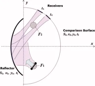
Fig. 9. (Color online) Geometry of the reflector-type beam split-ter and basic notations.
On performing certain derivations and using adjoint inte-gral operators, we finally obtain
I x1 = 2 Re兵− 共Ux 10 0 + Gˆ x10,11j兲 − j¯共Gˆx1,11 * − Gˆx 10,21 * 兲其, 共7兲 where auxiliary function satisfies an adjoint SIE:
Gˆ11* = Gˆ21* . 共8兲
Thus the x1component of the gradient of our objective
function satisfies a SIE whose operator is a complex con-jugate to that of the analysis SIE(2). The right-hand-part function of adjoint SIE is determined after solving Eq.(2) with a first-guess contour S1, obtaining residual function
(3), and integrating it along contour S2.
Note that the operators involved in Eqs. (7) and (8) have either smooth or logarithmic-singular kernels. Therefore all of them can be efficiently computed with the MDS discretization of Section 3. The total gradient of the objective function is given by Eq.(7)and a similar expres-sion forI/y1.
5. NUMERICAL RESULTS FOR BEAM
SPLITTER SYNTHESIS
To test the idea of the semianalytical gradient synthesis based on the SIE-MDS technique, consider the problem of designing a single-reflector beam splitter, S1 (see Fig.9),
of the field radiated by a CSP feed. The comparison con-tour S2 is taken as a half-circle with two isolated
inter-vals, L1and L2, on which the field of the synthesized
re-flector is to be focused. Therefore the prescribed field function on this contour is taken as a superposition of two identical Gaussian functions having maxima at the cen-tral points of L1and L2.
As the initial guess, we took an elliptic contour S1 of
the fixed aperture size d = 35, having the feed placed at its first focus F1 (Fig.10). The feed field is fixed, having
the aperture parameter kb = 8 (b is the imaginary part of
the source coordinate). Such a feed, if placed at the focal point F1and aimed at the center of S1, provides a −10 dB
edge illumination of the reflector. The intervals L1and L2
are located behind the other geometrical focal point F2,
and the comparison contour S2diameter is 48.
After performing the synthesis as explained above, we compared the prescribed (Fig.11, dashed curve) and the optimized (solid curve) field amplitudes on S2. A very
close similarity between the two curves is observed at the intervals corresponding to the bright spots; the corre-sponding value of the objective function is found to be 10−2. The total near field of the synthesized reflector is
shown in Fig. 12. A clear splitting of the reflected beam and its focusing on the desired intervals L1and L2is seen.
The proposed synthesis method has been implemented on a personal computer in MATLAB, and the widely used
Fig. 11. (Color online) Initial, prescribed, and synthesized field amplitudes on a semicircular normalized contour S2for a
non-symmetrically fed reflector (see Fig.10).
Fig. 12. (Color online) Near field of the synthesized reflector beam splitter.
Fig. 10. (Color online) Near field of the initial d = 35 elliptic re-flector with a2/ a1= 0.8 fed by an in-focus CSP source.
BFGS-algorithm has been applied to minimize I. Approxi-mately 25 function calls for 600 surface variables x1, y1
and 1.5 h of computing with a P4 2.6 GHz processor were necessary to generate the results shown in Figs.11 and 12. These parameters can be greatly reduced if initial-guess contour S1and comparison contour S2are chosen in
the optimal way.
6. CONCLUSIONS
We have presented a 2D accurate and efficient numerical analysis of the reflector beam waveguides made of several PEC elliptic mirrors. This has been achieved with the aid of the SIE-MDS approach. The main feature of a beam waveguide is an ability to focus the beam and reproduce the near-field pattern after each reflector. As a simple fig-ure of merit, we have studied the field amplitudes in the consecutive focal points of confocal elliptic reflectors un-der the variation of various parameters. Our analysis has shown that the ability of the chain of reflectors to guide the wave radiated by an aperture source strongly depends on the edge illumination of the first reflector and on the proper placement of the source. For in-focus source, the edge illumination of a 20 reflector should not be higher than −12 dB.
Numerical synthesis is a much more complicated en-deavor than analysis. We have tested the SIE-MDS tech-nique as a full-wave engine for building a synthesis code based on a seminumerical gradient method. As we have found, if the objective function is the deviation of the near field from a given function on a certain open or closed con-tour, it is possible to derive a separate SIE for the gradi-ent of the objective function and to solve it with the MDS as well. This speeds up the synthesis process and guaran-tees accuracy. Example of the synthesis of a shaped reflec-tor has been given to demonstrate the splitting of the in-cident Gaussian-like beam into two high-intensity spots at prescribed locations.
ACKNOWLEDGMENTS
The authors are grateful to the Technical University of Hamburg–Harburg and Bilkent University for providing their facilities and computing resources. This work was supported in part by the Turkish Council for Research in Science and Technology and the National Academy of Sci-ences of Ukraine via joint research projects EEEAG-103E037 and 106E209 and by the Euler-DAAD Program and the SUMMA Foundation with student awards to A. A. Nosich.
REFERENCES
1. Feature issue, “Diffractive optics applications,” Appl. Opt.
34, 2399–2559 (1995).
2. J. M. Bendickson, E. M. Glytsis, and T. K. Gaylord, “Metallic surface-relief on-axis and off-axis focusing diffractive cylindrical mirrors,” J. Opt. Soc. Am. A 16, 113–130 (1999).
3. J. M. Bendickson, E. N. Glytsis, and T. K. Gaylord, “Focusing diffractive cylindrical mirrors: rigorous
evaluation of various design methods,” J. Opt. Soc. Am. A
18, 1487–1494 (2001).
4. B. Z. Katsenelenbaum, “Transmission of millimetric waves by reflection from a series of focusing mirrors (Approximate theory of millimetric wave transmission, using reflections from row of focusing mirrors),” Radio Eng. Electron. Phys.
8, 1455–1460 (1963) [Radiotekh. Elektron. (Moscow) 8,
1516–1522 (1963)].
5. J. E. Degenford, M. D. Sirkis, and W. H. Steier, “The reflecting beam waveguide,” IEEE Trans. Microwave Theory Tech. 12, 445–453 (1964).
6. B. Z. Katsenelenbaum, “Quasioptical methods of generation and transmission of millimeter waves,” Sov. Phys. Usp. 7, 385–400 (1964) [Usp. Fiz. Nauk 83, 31–105 (1964)].
7. V. S. Averbakh, S. N. Vlasov, and V. I. Talanov, “Methods of mode selection in quasioptical systems,” Radiophys. Quantum Electron. 10, 747–760 (1967) [Izv. Vyssh. Uchebn. Zaved. 10, 1333–1357 (1967)].
8. R. Tremblay and A. Boivin, “Concepts and techniques of microwave optics,” Appl. Opt. 5, 249–278 (1966).
9. G. Goubau and P. D. Coleman, “Beam waveguides,” in E. C. Okress, ed., Microwave Power Engineering (Academic, 1968), Vol. 1, pp. 228–255 (1968).
10. P. F. Goldsmith, Quasioptical Systems: Gaussian Beam, Quasioptical Propagation and Applications (IEEE, 1998). 11. A. Fernandez, K. M. Likin, P. Turullols, J. Teniente, R.
Gonzalo, C. del Rio, J. Marti-Canales, M. Sorolla, R. Martin, “Quasioptical transmission lines for ECRH at TJ-II stellarator,” Int. J. Infrared Millim. Waves 21, 1945–1957 (2000).
12. M. K. Thumm and W. Kasparek, “Passive high-power microwave components,” IEEE Trans. Plasma Sci. 30, 755–786 (2002).
13. P. F. Goldsmith, “A quasi-optical feed system for radio-astronomical observations at mm wavelength,” Bell Syst. Tech. J. 56, 1483–1501 (1977).
14. L. B. Felsen, “Quasi-optic diffraction,” in Proceedings of Symposium on Quasi-Optics (P. I. Brooklyn Press, 1964), pp. 1–40.
15. J. A. Murphy, “Distortion of a simple Gaussian beam on reflection from off-axis ellipsoidal mirrors,” Int. J. Infrared Millim. Waves 8, 1165–1187 (1987).
16. L. Empacher and W. Kasparek, “Analysis of a multiple-beam waveguide for free-space transmission of microwaves,” IEEE Trans. Antennas Propag. 49, 483–493 (2001).
17. T. Bondo and S. B. Sorensen, “Physical optics analysis of beam waveguides using auxiliary planes,” IEEE Trans. Antennas Propag. 53, 1062–1068 (2005).
18. D. W. Prather, M. S. Mirotznik, and J. N. Mait, “Boundary integral methods applied to the analysis of diffractive optical elements,” J. Opt. Soc. Am. A 14, 34–43 (1997). 19. J. M. Bendickson, E. N. Glytsis, and T. K. Gaylord, “Scalar
integral diffraction methods: unification, accuracy, and comparison with a rigorous boundary element method with application to diffractive cylindrical lenses,” J. Opt. Soc. Am. A 15, 1822–1837 (1998).
20. M. Testorf, “On the zero-thickness model of diffractive optical elements,” J. Opt. Soc. Am. A 17, 1132–1133 (2000). 21. T. Oguzer, A. I. Nosich, and A. Altintas, “E-polarized beam scattering by an open cylindrical PEC strip having arbitrary “conical-section” profile,” Microwave Opt. Technol. Lett. 31, 480–484 (2001).
22. A. A. Nosich and Y. V. Gandel, “Numerical analysis of quasi-optical multireflector antennas in 2-D with the method of discrete singularities,” IEEE Trans. Antennas Propag. 55, 399–406 (2007).
23. J. Tsalamengas, “Exponentially converging Nystrom’s methods for systems of SIEs with applications to open/ closed strip or slot-loaded 2-D structures,” IEEE Trans. Antennas Propag. 54, 1549–1558 (2006).