CO
2laser polishing of conical shaped optical fiber deflectors
Elif Uzcengiz S¸ims¸ek1,2 · Bartu S¸ims¸ek1,2 · Bülend Ortaç1,2
Received: 29 October 2016 / Accepted: 13 May 2017 / Published online: 25 May 2017 © Springer-Verlag Berlin Heidelberg 2017
have been proposed and several types are currently used for tissue ablation. The types of deflector shapes are bare, side-firing and radial. Bare fiber optic deflectors (basic deflector geometry) transmit the laser energy in the same direction along the fiber. Side-firing optical fiber optical deflectors transmit laser light perpendicular to the fiber axis through specific direction and they are widely used in many medical applications, especially in the prostate tumor ablation [1]. One of the most popular deflector types is radial design. Radial fiber optic deflectors with conically shaped optical fiber end transmit the laser energy radially and the laser energy is homogeneously distributed into a ring-shaped beam. These deflectors are especially used in endovenous laser ablation (EVLA) [2]. Unlike other cone-shaped fiber optical probes [3–7] used for various applications, EVLA operation needs μm-scale, multimode (MM) optical fib-ers and specific cone-angle values to fulfill the EVLA operation requirements. Thus, multi-mode, larger NA and μm-scale optical fibers are preferred in the operations. The homogeneous, ring-shaped laser energy distribution can be achieved with large cone angles which are detailed in this study. It allows a perfect irradiation of vein walls and their ablation. Among existent fiber processing methods such as chemical, FIB [3–5], mechanical polishing method is the best candidate to obtain such desired cone-angles. Furthermore, mechanical polishing process is applicable for mass-production of conical shaped optical fibers used in EVLA operation. In the mechanical polishing process, the deflector geometry is first formed with rough lapping film, then, the surface roughness of the deflector is gradu-ally smoothed by polishing with smoother lapping films [8]. This process is composed of several steps to obtain high quality surface structures and a well-prepared fiber deflector surface eliminates the optical losses such as scat-tering and back reflection. However, the mechanical fining Abstract A novel method for polishing conical shaped
optical fiber deflectors by modulated CO2 laser exposure is
reported. The conical shaped fiber deflector geometry was first formed with rough mechanical polishing, then it was exposed to modulated CO2 laser operating with wavelength at 10.6 µm to achieve fine polish surfaces. The motivation of this work is to demonstrate that the modulated CO2 laser exposure approach allows a fiber surface roughness at a nanometer scale without modifying the conical shape of the fiber deflector. The average surface roughness of mechani-cally polished fiber deflectors with 30 and 9 µm lapping films was smoothed down to 20.4 and 4.07 nm, respec-tively, after CO2 laser polishing process. By combining mechanical and laser polishing techniques, fabrication of conical shaped optical fiber deflectors takes less time and it becomes laborer independent and easy to apply.
1 Introduction
Fiber optical probes are ideal tools for numerous applica-tions such as material processing, imaging, and spectros-copy. The use of fiber optical probes for medical treatment opens the door for minimally invasive surgery applications, as they possess a smaller size and efficiently transmit the laser light with different shapes and directions by manipu-lating their deflector’s geometry. Different deflector designs
* Bülend Ortaç
1 Institute of Material Science and Nanotechnology, Bilkent
University, 06800 Ankara, Turkey
2 National Nanotechnology Research Center, Bilkent
process of the fiber deflectors takes very long time and it is laborer dependent. In the paper, we develop a surface treatment technique for polishing conical shaped optical fiber deflectors by combining rough mechanical polishing and nanoscale surface roughness polishing with modulated CO2 laser treatment. In the literature, it was reported that
the bare fiber end could be polished down to 100 nm sur-face roughness by continuous wave CO2 laser exposure [9]. In our approach, the modulated CO2 laser exposure permits the control of thermal loading issue on a thin surface layer and volume melting, surface reflow, deformation of deflec-tor shape could be avoided. A very smooth surface rough-ness about 4.07 nm can be achieved by using this approach. This also provides less-time consuming and laborer inde-pendent procedure. In this paper, the conical fiber deflec-tor requiring meticulous design and fabrication process was investigated in terms of design, surface roughness profile and light deflection measurements.
2 Deflection angle calculation and simulation
2.1 Ray tracing calculation
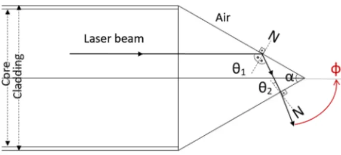
Conical shaped fiber deflector provides a side deflection geometry and it forms a circular beam pattern. We used Snell’s law and ray tracing calculations for determining the relation between deflection angle and cone angle. Ray trac-ing method is a powerful tool to identify the light deflection behavior of the conical fiber deflector. The ray tracing pat-tern of the conical shaped fiber deflector is shown in Fig. 1. When the laser beam reaches to the deflector, it comes to the first core-air boundary. At this boundary, it is reflected by obeying the total internal reflection (TIR) since the criti-cal angle between core-air boundary, θcore-air is calculated as θcore−air = sin−1(nair/ncore) which equals to 43.3° when
the deflector angle in the range of α<π−2θcore-air to obtain
side deflection. θ1 equals to (180 − α)/2 and θ1 becomes 60° which means that θ1˃ θcore-air and it confirms the TIR
at this boundary. Then, the reflected ray travels through the second core-air boundary and its incoming ray is θ2 and it is calculated by θ2 = |90 + θ1 − α| from the geometry.
The laser beam is refracted at this boundary; the refraction angle is calculated as θrefracted = sin−1((ncore/nair)sinθ2) .
Using these calculations, the relation between deflection angles becomes as Eq. 1 [10]:
Using Eq. 1, θ1 becomes 60° which means that θ1>θ
core-air and it confirms the TIR at first core-air boundary, θ2
(1) φ = 180 − α
2 − θrefracted
becomes 0°, thus, θrefracted goes to zero and the deflection angle is found as 60° when the deflector angle is 60° which is in the range of α<π−2 θcore-air.
2.2 Ray tracing simulation
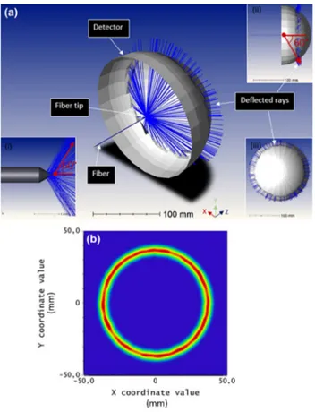
For further analysis, we also performed numerical simu-lation analysis. The fiber geometry was created in non-sequential part of Zemax software. We used a fiber having refractive index of core/clad of 1.45/1.39 (Thorlabs, USA) in the air environment. The radius of the core/clad was 600/630 µm and numerical aperture (NA) was 0.39. The rays are coupled inside the fiber (by using fiber.dll source in Zemax) and 10,000 rays were analyzed, only the 50 of the rays are shown in the simulation results (see Fig. 2).
In Fig. 2a, the general overview of simulation con-figuration is represented. A semi-spherical detector hav-ing 50 mm diameter was used to cover the circular beam. The fiber is in the center of the semi-spherical detector. The incoming rays are emitted from the deflector and they form a homogeneous circular beam shape. The 60° deflection angle of the rays is observed and this result is in a good agreement with calculation presented in Eq. 1. In Fig. 2b, the image of the light deflection from conical shaped fiber deflector on semi-spherical detector is repre-sented and a homogeneous circular beam shape could be obtained.
2.3 Surface roughness and reflectance relation
In this section, the relation between surface roughness and reflectance is evaluated to estimate the surface roughness level which is necessary to obtain sufficient level of perfor-mance. For finding the reflection coefficient at the glass-air boundary, we evaluated our case when the cone-angle is 60°. Since the incoming rays totally reflected from the first sur-face, they travel at the normal of the second surface which means that the incoming angle is 0°. Thus, in our case, reflec-tion coefficient at the second surface becomes rperp≅ rpar = r. The following equations represent rperp and rpar in Eqs. 2, 3:
(2) rperp= nicos θi− ntcos θt nicos θi+ ntcos θt , (3)
rpar= ntcos θi− nicos θt nicos θi+ ntcos θt.
When the angle between incoming rays and the surface normal is 0°, the equations become as Eq. 4:
When ni = 1.45 and nt = nair≅ 1, the reflection
coef-ficient at the second surface boundary is calculated as 0.18. The reflectance, R equals to r2 which is 0.03. Then,
using T = 1−R, transmission (T) at the boundary becomes 0.97. The relation between surface roughness and reflec-tance is also studied in terms of theory and simulation. The reflectance from a surface depends on Rs, the light specu-larly reflected from the surface and Ro, the total amount of light reflected by the sample. The ratio between Rs and
Ro is related with the surface roughness value (σ) and
wavelength of the incoming rays (λ). If the distribution of heights of the surface irregularities is gaussian, this ratio gives rms surface roughness, σ in Eq. 5 [8]:
When σ approaches to λ, the scattering becomes signifi-cant and the ratio between Rs and Ro becomes smaller. To obtain high Rs and Ro ratio, for example 0.9–1, the σ/λ must be in the range of 0–0.1. In our case, λ was 635 nm, thus, surface roughness (σ) of the cone-shaped deflector must be less than 60 nm to achieve high Rs/Ro. Zemax simula-tions are run to verify the theoretical study. It uses K-corre-lation function to simulate the effect of surface roughness [11]. This function adds roughness to surface of mirrors, lens, optical fibers etc. To evaluate the effect of the sur-face roughness from the conical shaped deflector, different roughness values were assigned to the end-face of it where the deflection of light occurs. In Fig. 3a, Zemax simulation (4) r= ni− nt ni+ nt (5) Rs Ro =exp − 4π σ 2
Fig. 2 Numerical simulation results. a Light deflection from the fiber deflector (i), Y–Z plane image of the setup (ii) and X–Z plane image of the setup (iii) and b the image of the light deflection from conical shaped fiber deflector on semi-spherical detector
Fig. 3 a The intensity distribution of cone-shaped deflector for different surface roughness values, b comparison of the theoretical calculation and Zemax simulation results
was performed for surface roughness values of 30, 50, 100 and 150 nm and the intensity distribution of cone-shaped deflector for different surface roughness values are repre-sented. Ro is considered for the no roughness case, and the other results peak points are taken as Rs, Rs/Ro is obtained for each case. In Fig. 3b, comparison of Zemax simulation and the theoretical results are shown. The theoretical func-tion and the simulafunc-tion results have a good agreement.
3 Material and method
3.1 CO2 laser–silica interaction
Silica (SiO2) is the main ingredient of most glasses and has a tetrahedral structure with one silicon (Si) bound to four oxygen atoms. Silica has a wide range of high opti-cal transparency from ultraviolet (UV) region of 0.2 µm to infrared (IR) spectral region of 3.5 µm. Light absorption of glass in the range below 0.3 µm is dominated by elec-tronic excitation of molecules, while molecular vibrations are dominated in the IR range [12]. In IR regime, the band of high absorption in the wavelength range of 8 to 11 µm is attributed to the bond-stretching vibration between the Si and O atoms in a Si–O–Si bridge structure. On the other hand, CO2 laser operating in IR regime is a potential laser
candidate and it is relatively cheaper than sources operat-ing in UV regime. CO2 lasers are also easy to access and effective sources to processing silica glass. The central wavelength of CO2 laser is around 10.6 µm and photon
energy is approximately 0.2 eV. The radiation of CO2 laser is not enough to brake the bonds of Si–O, so it is strongly absorbed by Si–O vibrational modes and converted into heat. Depending on CO2 laser parameters, particularly
pulse duration, pulse repetition frequency, peak power, and spot diameter, CO2 laser could be used for polishing of silica glass. In the laser polishing process, high repetition rate laser pulses with relatively low axial irradiance gener-ate a raised temperature on the glass surface, sufficient to melt a thin surface layer that flows under surface tension. For fused silica, generation of a highly mobile glass layer is obtained without significant mass loss when the glass viscosity is in the range between 102 and 105 Pa s. This
range corresponds to surface temperatures from 2000 to 2700 °C [13]. In the literature, there are reports on glass processing by controlling the glass viscosity below the ablation threshold using a CO2 laser beam. These works provide an improvement of the surface damage resistance in fused silica optics [14, 15], localized repairing of dam-ages in fused silica optics [16–18], laser polishing of con-ventional glasses [19, 20] and optical fiber end surfaces [9,
21] and, also, in the manufacturing of micro-optical com-ponents. In our approach, modulation of CO2 laser takes an
important place for smoothing the silica glass and fiber sur-faces without deforming the delicate conical shaped opti-cal fiber deflectors. Below the silica ablation threshold, the heat penetration depth (1D) is smaller than the laser spot diameter and the surface temperature is kept down by the pulse energy for short pulse widths. For longer pulses; on the contrary, the penetration depth is increased along both radial and axial direction with larger heated spot radius [22]. When the pulsed CO2 laser exposed on SiO2 surface, the energy dissipated in several µm depth and the surface of glass melts and gets into fluidic phase and it turns into solid when the exposure is over. The cracks and scratches located on the silica glass or optical fiber surface are elimi-nated and smoothened under favor of this process. On the other hand, applying longer pulses or continuous wave CO2 laser to process silica glass or optical fiber causes deforma-tion on its structure, such as forming ball lens at the end of optical fiber.
4 Experimental section
4.1 Sample preparation and CO2 laser treatment process
The cone-shape was first formed by one step rough mechanical polishing process using mechanical polish-ing machine (Ultrapol, USA). There are two types of mechanical polished fibers which are prepared with 30 and 9 µm lapping films. The deflector angle of both fibers was adjusted as ~60°. The traditional mechanical polish-ing procedure continues with finer lapppolish-ing films in order to decrease the roughness of the fiber deflector. Instead of continuing with mechanical fine polishing, the cone-shaped fiber deflectors could be smoothened by one step CO2 laser exposure procedure. The CO2 laser exposure was modulated since continuous-wave laser exposure may change the shape of the fiber deflector. The cone-shaped fiber deflector is prone to be a ball lens after being exposed to continuous-wave CO2 laser, thus, a special function was developed to modulate the laser. The fiber glass process-ing machine LZM 100 (AFL, Japan–USA) for controlled CO2 laser polishing experiment is illustrated in Fig. 4a. The fiber is homogeneously exposed to the laser from both sides of the fiber deflector. The shutter was used to modulate the laser beam. The fiber processing machine could show the hot images of the fiber during the process. Hot images are visual data guiding the process to give the information on the evolution of deflector geometry during the laser exposure. The graph shown in Fig. 4b was plot-ted by the machine itself based on the laser average power data vs. time data taken by thermo-coupled detector. We have performed several configurations (laser power, pulse
duration, number, and period) in order to optimize the laser polishing process. In the machine settings, there is a function to determine laser power which is the minimum power to melt standard single mode fiber (SMF). Editing this function, we designated the minimum laser power to melt our fibers using in the experiment. The selected power intensity of the beam was 9.15 × 10³ W/cm2. After
selecting laser power, we have performed different laser pulse durations (0.75, 1 and 1.25 s) on conical shaped optical fibers. 0.75 s laser pulse was not enough to melt fiber surface, so we investigated the effect of 1 s and 1.25 s pulses on fiber surface and shape. The laser pulse of 1.25 s transform the shape of fiber deflector into ball shaped fiber end. Therefore, the pulse duration of CO2 laser was deter-mined as 1 s.
Number and period of laser pulse are also important steps of optimization process. Period of pulse was deter-mined by investigating thermal behavior of heated fiber tip. The CO2 laser was modulated as 1-s duration and 2-s interval to cool surface of fiber efficiently. In order to get minimum number of pulse, we have designed the study for 30 and 9 μm polished fibers. We have applied three dif-ferent numbers of pulse values; 8, 16 and 24 pulses for each fiber tip polished at both 30 and 9 μm lapping films. We obtained SEM images of each fiber surface as seen in the Table 1. When we analyze the results, 8 laser pulse is clearly insufficient, 16 laser pulse gives smooth surface and 24 pulse gives best results in terms of surface rough-ness of conical shaped optical fiber deflectors. As a result of optimization process, the geometry of the CO2 laser-polished fiber deflector remained as cone-shaped, and the fiber end-face surface is gradually smoothed by laser exposure.
5 Results and discussion
In Fig. 5a, SEM image of the fiber deflector polished with commercially available 30 µm lapping film (Krell Tech, USA) is shown. The rough fiber surface was exposed to modulated CO2 laser beam. A smooth fiber deflector sur-face was successfully obtained as shown in Fig. 5b, after CO2 laser surface treatment. Due to the larger initial
sur-face roughness structures obtained by mechanical polish-ing process, we also observed surface waviness. In the second experiment, we used 9 µm lapping film for rough mechanical polishing. The conical shaped fiber optical deflector geometry is obtained. In Fig. 5c, SEM image of the fiber deflector polished with 9 µm lapping film (Krell Tech, USA) is shown. We also applied the same CO2 laser treatment procedure. The conical shape of the deflector is protected after laser exposure and the SEM image of the deflector (see Fig. 5d) demonstrated that the surface quality of the deflector is definitely improved.
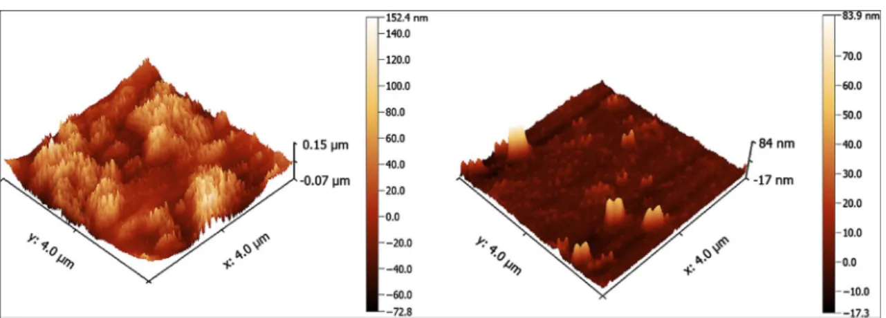
In order to study the surface morphology of the deflec-tors, the AFM analysis was performed. AFM surface roughness images are represented in Fig. 6. The mechani-cally polished fiber end-face surfaces could not be ana-lyzed since their surfaces were much rough for the AFM deflector. Any clear image of the fiber deflectors pol-ished with 30- and 9 µm-rough lapping films could not be obtained to avoid damaging the AFM tip. After the CO2 laser exposure, the fiber surfaces were smoothened,
and we were able to study the surface profiles by AFM. 4 × 4 µm area was scanned by the AFM deflector. The conical surface of the fiber deflector restricted the area that we could scan since it has a curved surface. The aver-age surface roughness of mechanically polished fiber
deflectors with 30 and 9 µm lapping films were smoothed down to 20.4 and 4.07 nm, respectively, after CO2 laser polishing process.
Our approach clearly demonstrates that sub-10 nm aver-age surface roughness of conical shaped fiber deflectors could be obtained by combining rough mechanical and
Table 1 SEM images of conical shaped optical fiber deflectors with different number of pulses and initial lapping film
Scale bars 50 μm
Fig. 5 SEM images of fiber deflectors a polished on 30 µm-rough film, b after expo-sure to modulated CO2 laser and
c polished on 9 µm-rough film, d after exposure to modulated CO2 laser (insets show the
Fig. 6 AFM images of fiber deflectors a mechanically polished with 30 μm lapping film and modulated CO2 treatment, b mechanically
pol-ished with 9 μm lapping film and modulated CO2 treatment
Fig. 7 a Characterization of spatial light distribution of the coni-cal shaped fiber deflectors. Spatial light distribution graphs of fiber deflectors mechanically polished with 30 μm lapping film (black line) and modulated CO2 treatment (blue line) b and mechanically
polished with 9 μm lapping film (black line) and modulated CO2 treatment (blue line) c and the insets in the graphs belong to the dem-onstration of circular light deflection from conical shaped deflectors for each measurement
fine CO2 laser polishing process. The surface roughness of the fiber deflector affects the light deflection properties. In order to analyze the effect of the surface roughness to the light deflection, the spatial light distribution of the fiber deflectors was measured by the home-built characteriza-tion setup represented in Fig. 7a. The detector located on the rotating stage revolves around the optical fiber deflector while collecting the power data. An aperture was attached in front of the detector to analyze light deflection more accurately. A fiber coupled diode laser emitting at 635 nm (ThorLabs, USA) was launched to the optical fiber. Light deflection was measured on mechanically polished deflec-tor and CO2 laser polishing treated deflector. The normal-ized intensity vs. deflection angle graph of the fiber deflec-tors was plotted according to data obtained from the setup in Fig. 7a. In Fig. 7b, c, black line belongs to light deflec-tion of the fiber deflector which was mechanically polished with 30 and 9 µm lapping films.
The intensity distribution does not change signifi-cantly along the plot. This means that mechanically pol-ished deflector scatters all coming light. After applying the CO2 laser polishing to mechanically polished deflector, the
intensity of the CO2 laser-treated fiber deflector increased 8.6 times comparing to the intensity of non-treated deflec-tor. The blue line represents the light intensity distribution after laser polishing. The center of maximum light inten-sity of the laser polished deflector is 58° deflection angle. In Fig. 7c, black line belongs to deflection of the fiber deflector mechanically polished with 9 µm-lapping film. The blue line shows the light intensity after the CO2 laser polishing of the
deflector. The intensity of the CO2 laser-treated fiber deflec-tor was 2.8 times more than the intensity of non-treated deflector. The insets in Fig. 7b, c demonstrate light deflection from untreated and treated fiber surfaces and the deflected power. Light distribution increased due to elimination of the cracks and scratches by the CO2 laser exposure. In this case, the center of maximum light intensity of the laser-polished deflector is 62° deflection angle. The deflection angle of both cases was in agreement with the calculated values of our design (Eq. 1). The FWHM of light deflection beam outputs for both before and after CO2 laser exposure were measured. For the case in Fig. 7b, the FWHM of the beam output of mechanically polished fiber deflector was decreased from 49° to 18.7°, and for Fig. 7c the FWHM decreased from 20° to 13° after CO2 treatment of fiber deflector surface. This also indicates the surface smoothening of fiber deflector by CO2 laser exposure for both experiments.
6 Conclusion
The conical shaped optical fiber deflectors have been developed through a two-step polishing techniques of
combining mechanical and CO2 laser treatments. Once the conical shape of the fiber deflectors is formed by 30 µm- and 9 µm-rough polishing films, a modulated CO2 laser process is applied to obtain very smooth fiber deflector surface. The rest of the mechanical polishing procedure could be omitted due to easy and fast CO2 laser
polish-ing. AFM surface analysis shows that the roughness of the mechanically polished fiber deflectors at 30 and 9 µm films can be decreased down to 20.4 and 4.07 nm, respectively, after optimized CO2 laser polishing. A new method of
combining mechanical and CO2 laser polishing makes the fabrication of conical fiber deflectors easy, fast and laborer independent.
Acknowledgements We thank Mustafa Fadlelmula for his assistance with atomic force spectroscopy (AFM) analysis. We would also like to show our gratitude to Canan Kurs¸ungöz for reading and making comments that improved the manuscript.
References
1. A.K. Ngo, N.M. Fried, Side-firing germanium oxide optical fib-ers for use with erbium: YAG laser. J. Endourol. 20(7), 475–478 (2006)
2. F. Pannier, E. Rabe, J. Rits, A. Kadiss, U. Maurins, Endovenous laser ablation of great saphenous veins using a 1470 nm diode laser and the radial fibre–follow-up after six months. Phlebology 26(1), 35–39 (2011)
3. A. Kuchmizhak, S. Gurbatov, A. Nepomniaschii, O. Vitrik, Yu. Kulchin, High-quality fiber microaxicons fabricated by a modi-fied chemical etching method for laser focusing and generation of Bessel-like beams. Appl. Opt. 53, 937–943 (2014)
4. Raoul Stöckle, Christian Fokas, Volker Deckert, Renato Zenobi, High-quality near-field optical probes by tube etching. Appl. Phys. Lett. 75, 160 (1999)
5. S. Cabrini, C. Liberale, D. Cojoc, A. Carpentiero, M. Prasciolu, S. Mora, V. Degiorgio, F. De Angelis, E. Di Fabrizio, Axicon lens on optical fiber forming optical tweezers made by focused ion beam milling. Microelectron. Eng. 83, 804–807 (2006) 6. T. Grosjean, S.S. Saleh, M.A. Suarez, I.A. Ibrahim, V. Piquerey,
D. Charraut, P. Sandoz, Fiber microaxicons fabricated by a pol-ishing technique for the generation of Bessel-like beams. Appl. Opt. 46, 8061–8067 (2007)
7. S.-K. Eah, W. Jhe, Nearly diffraction-limited focusing of a fiber axicon microlens. Rev. Sci. Instr. 74, 4969 (2003)
8. J.M. Bennett, R.J. King, Effect of polishing technique on the roughness and residual surface film on fused quartz optical flats. Appl. Opt. 9, 236–238 (1970)
9. U. Mircea, H. Orun, A. Alacakir, Laser polishing of optical fiber end surface. Opt. Eng. 40(9), 2026–2030 (2001)
10. T. Watanabe, Y. Matsuura, Side-firing sealing caps for hollow optical fibers. Lasers Surg. Med. 38(8), 792–797 (2006)
11. S. Gangadhara, “How to model surface scattering via the K-cor-relation distribution”, published on 2008, updated on 2010.
www.zemax.com. Received on 21 Jan 2017
12. D.W. Lane, The optical properties and laser irradiation of some common glasses. J. Phys. D Appl. Phys. 23(12), 1727 (1990) 13. K.L. Wlodarczyk, Surface deformation mechanisms in laser
smoothing and micromachining of optical glasses, Diss. Heriot-Watt University, 2011
14. P.A. Temple, W.H. Lowdermilk, D. Milam, Carbon dioxide laser polishing of fused silica surfaces for increased laser-damage resistance at 1064 nm. Appl. Opt. 21(18), 3249–3255 (1982) 15. P. Cormont, P. Combis, L. Gallais, C. Hecquet, L. Lamaignère,
J.L. Rullier, Removal of scratches on fused silica optics by using a CO2 laser. Opt. Express 21, 28272–28289 (2013)
16. N. Shen, M.J. Matthews, J.E. Fair, J.A. Britten, H.T. Nguyen, D. Cooke, S. Elhadj, S.T. Yang, Laser smoothing of sub-micron grooves in hydroxyl-rich fused silica. Appl. Surf. Sci. 256(12), 4031–4037 (2010)
17. C. Buerhop, B. Blumenthal, R. Weissmann, Glass surface treat-ment with excimer and CO2 lasers. Appl. Surf. Sci. 46(1-4), 430–434 (1990)
18. S. Palmiera, L. Gallaisa, M. Commandréa, P. Cormontb, R. Courchinouxb, L. Lamaignèreb, J.L. Rullierb, P. Legrosc, Opti-mization of a laser mitigation process in damaged fused silica. Appl. Surf. Sci. 255(10), 5532–5536 (2009)
19. M. Serhatlioglu, B. Ortaç, C. Elbuken, N. Biyikli, M. Solmaz, CO2 laser polishing of microfluidic channels fabricated by fem-tosecond laser assisted carving. J. Micromech. Microeng. 26, 115011 (2016)
20. F. Laguarta, N. Lupon, J. Armengol, Optical glass polishing by controlled laser surface-heat treatment. Appl. Opt. 33(27), 6508– 6513 (1994)
21. A. Kuhn, P. French, D.P. Hand, I.J. Blewett, M. Richmond, J.D. Jones, Preparation of fiber optics for the delivery of high-energy high-beam-quality Nd: YAG laser pulses. Appl. Opt. 39(33), 6136–6143 (2000)
22. E. Mendez, K.M. Nowak, H.J. Baker, F.J. Villarreal, D.R. Hall, Localized CO2 laser damage repair of fused silica optics. Appl. Opt. 45(21), 5358–5367 (2006)