Investigation of materials and damage sources
of local masonry structures in Turkey
B. Zengin
1, M. Bulduk
2, E. Aydın
2, E. Koşar
2& A. Z. Altay
2 1Vocational School, İstanbul Gelisim University, Istanbul, Turkey
2Department of Civil Engineering, Yıldız Technical University, Turkey
Abstract
Masonry buildings are preferred for reasons such as their ease of production, low cost and of obtaining materials. While these materials are preferred in rural areas due to their low cost, they are also an option in urban regions. The majority of the buildings in Turkey’s rural regions consist of masonry buildings, with materials being obtained locally. However, almost none of these buildings exhibit earthquake resistance. Masonry buildings that have been damaged in recent earthquakes throughout Turkey support this argument. In this paper, earthquake damage to masonry buildings built using locally obtained materials, the material properties, and the architectural and load-bearing systems of these buildings were investigated and the sources of damage were determined.
Keywords: masonry building, stacked material, earthquake.
1 Introduction
Distinctive geographical features, topography, climate and living conditions of a region cause people to integrate with that region and habitat, and hence create an authentic cultural character. A closed economy and limited means of transportation require the use of local construction materials. Kuban [1] states that by the principle of continuation of past experiences and the assimilation of old traditions, the employer is dominant in the construction process [2]. It is very common, especially in the countryside, to encounter masonry buildings which reflect the characteristics of the region. If the historical development of masonry buildings is taken into account, it is seen that adobe, stone and timber have been used from ancient times to the present. In today’s technology, the same materials are being used more efficiently with bricks and briquettes. With knowledge of
material properties, the production of structural systems are made with these materials and their strength against earthquakes and other loads became important so, research studies have veered in this direction. Regarding materials of construction, with the exclusion of engineering practices in the production of these structures, namely mud walls, stone walls, and brick walls as structural systems in Turkey, every earthquake has caused severe damage to buildings. In this study, the materials and structures of masonry buildings were investigated and the sources of damage were examined in the case of an earthquake.
2 Masonry building materials and their properties
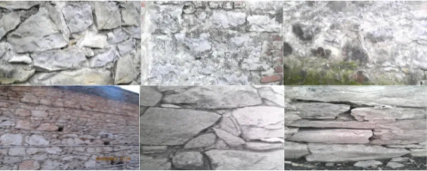
2.1 StoneNatural stone is one of the foremost masonry building materials of the ages (Fig. 1) and can easily be found in many regions of Turkey. Natural stone is a material that has high compressive but low tensile strength. Masonry stone buildings consist of load-bearing walls, which are composed of mortar and natural stone, as their sole structural system. The width of stone walls is within the range of 50 and 60 cm. When the loads of slabs and walls are considered, the used material’s strength is adequate to resist these vertical stresses [3]. The physical properties of some stones are presented in Table 1.
Figure 1: Examples of stonewalls. 2.2 Adobe
Adobe has a very high practical and economic value for the reasons that it can generally be obtained from almost anywhere, it does not require long and expensive transportation, skilled workmanship and mechanical systems are not needed for its production, and even though some mastery is required while building the wall, this mastery can easily be obtained locally (Figure 2).
A few adobe definitions found in literature:
a) “Raw bricks that are made by wetting the soil mixed with hay into loam, poured into wooden frames and dried under the sun.”
b) “Sun dried, framed loamed, used for building walls.” c) “Hay and loam mixture, primitive and raw brick.” [5].
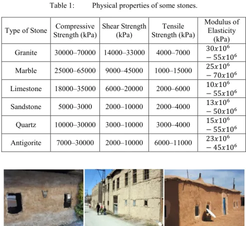
Table 1: Physical properties of some stones.
Type of Stone Compressive Strength (kPa) Shear Strength (kPa) Strength (kPa) Tensile Modulus of Elasticity (kPa) Granite 30000–70000 14000–33000 4000–7000 30𝑥10− 55𝑥106 6 Marble 25000–65000 9000–45000 1000–15000 25𝑥10− 70𝑥106 6 Limestone 18000–35000 6000–20000 2000–6000 10𝑥10− 55𝑥106 6 Sandstone 5000–3000 2000–10000 2000–4000 13𝑥10− 50𝑥106 6 Quartz 10000–30000 3000–10000 3000–4000 15𝑥10− 55𝑥106 6 Antigorite 7000–30000 2000–10000 6000–11000 23𝑥10− 45𝑥106 6
Figure 2: Adobe building examples.
Sunny weather and ambient temperatures are also important in adobe cutting. After being dried under the sun for three days, the adobe is turned upside down and becomes usable for construction in six or eight days. In adobe production, water procurement, choice of clayey soil, procurement of additives, mixing, framing, and drying are performed in that exact order. Adobe bricks that are brought to the construction site after drying are used as building material [6]. Adobe is a construction material that is obtained by mixing suitable soil with water and additives, cutting into big blocks using framework, and drying under the sun [5].
While adobe elements’ compressive strength is quite low, that of an average sample can reach up to 2 MPa [7]. Allowable shear strength for adobe walls is 0.05 MPa and allowable compressive strength for adobe blocks is 1.1 MPa [8]. 2.3 Timber
Timber, which is obtained from the trees, is a fibrous, heterogeneous, and anisotropic construction material. Timber’s physical properties are greatly
affected by humidity. The same timber behaves differently at different humidity levels. Timber contracts while drying and loses some of its volume. A timber-framed building should be placed at a certain height to rest on a stone infrastructure from the natural foundation in order to prevent it being affected by water [9]. When compared to masonry timber buildings, timber-framed systems have numerous advantages, such as a light frame setup, ability to form multi-story structures, ability to provide versatility in architectural solutions and economical timber usage. Wall elements produced by using timber can work or works in both compression and tension [10]. It has found a wide area of application because of its high workability and diversity in detailing analysis. In pine, the modulus of elasticity is 10,000 MPa, and 300 MPa, parallel and perpendicular to fiber directions, respectively. For both oak and beech, these values can be taken as 12,500 MPa and 600 MPa, respectively. The bending moment capacity of timber can have values ranging between 60 MPa and 130 MPa. For instance, while the bending moment capacity of third grade pine is 65 MPa, hornbeam’s bending moment capacity is 130 MPa.
2.4 Brick
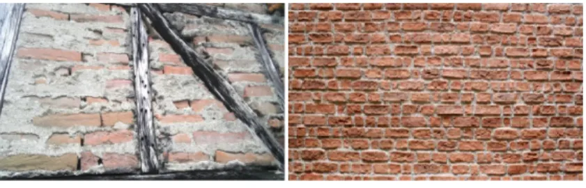
Brick is generally produced by mixing soil and loam, either separately or together, with sand, ground brick, tile powder, and other similar material, shaping it into rectangular containers, and baking it at 800–1200°C [11]. Because of its high water absorption capacity and unsaturated pores, brick causes adherence loss by absorbing water in the mortar. In addition, if the top of a brick wall is not plastered, excessive water absorption takes place and, due to freezing and thawing, its strength diminishes [12]. Some brick wall examples are presented in Figure 3. While solid clay brick’s compressive strength is 6 MPa, hollow brick’s compressive strength is 4 MPa [7].
Figure 3: Examples of brick wall. 2.5 Briquette
Concrete briquettes are produced by mixing light aggregate with cement, water, and additives, then placing in special frames and applying compression. These concrete blocks obtain their lightness from the properties of their aggregate composition. In these blocks, coal and coke slag, natural light aggregates (pumice stone, tuffs, etc.), baked clay, and mineral aggregates, which expand at high temperatures and suddenly cool afterwards, are used as aggregates [13]. The
average compressive strength of briquettes is 2 MPa [7]. The modulus of elasticity of a briquette wall is 2500 MPa [14].
3 Sources and types of damage in masonry buildings
The housing problem moves almost parallel to countrial development process with the rising socio-economic level. The current structure stock in Turkey, which we call rural structures, consists mainly of buildings that were built with masonry stone and a carcass system, without zoning or receiving any kind of civil engineering services. For this reason, every earthquake causes severe damage and loss of life in rural structures. Earthquake damage in these buildings can be briefly categorized into three main groups as “light”, “medium”, and “severe”. From these, severely damaged structures are beyond repair.
Seventy percent of masonry structures were severely damaged in earthquakes throughout Turkey up to now. Buildings that survived these earthquakes with light or no damage are at most 10%. In these types of buildings, in the case of an earthquake, the damage starts at the outer walls and, based on the magnitude of acting earthquake load, it advances, enveloping the partition walls. Therefore, in this structural system, where all walls are load-bearing, damage assessment is based on outer walls. Inclined shear cracks on the walls indicate that the earthquake direction is parallel to the walls. If the earthquake acts perpendicular to the walls, corner damage will be observed and horizontal and vertical cracks will either appear on the body of the wall or the existing cracks will further widen [3].
While building masonry structures, material used for construction such as brick, or stone briquette and their bonding level, vertical and horizontal joint configurations, behavior of materials and load-bearing elements, analysis, and construction rules should be considered. Since walls of masonry buildings are load-bearing elements, any damage on the walls directly affect the structural system [15].
3.1 Sources of damage observed in masonry structures
The sources of damage in masonry structures are: lack of a good connection between randomly placed elements at the joints of load-bearing walls with a strong mortar, very large door and window openings that disrupt the wall integrity. Lack of continuous concrete or timber girders that run around the outer walls and also placed in the inner walls, lack of a proper transition made with smooth-cut stones at the intersection of two perpendicular walls, increasing the weight of the structure by constructing a soil covered roof slab, and the use of multiple materials such as stone, adobe, and half-timber [16].
Due to earthquake loads, damage occurs in some regions of masonry structures. Because of stress concentrations, especially on the sides of doors and windows, masonry structures achieve their failure mechanisms with diagonal cracks. Turkish Seismic Code mandates that openings must be at least 1.5 m away from the corners of the structure. In Figure 4 below, this type of damage
can be observed in a structure that was affected by the Kocaeli earthquake in 1999.
In masonry walls that work perpendicular to the earthquake direction, vertical cracks are observed near the corners. In Figure 4 above, these types of cracks can also be seen. Furthermore, it can be said that the gable walls that are used in the attic are one of the foremost targets of earthquake damage [18].
Figure 4: Typical diagonal cracks in masonry structures [17]. 3.2 Damage types in masonry structures
In masonry structures some damage and cracks can occur in its elements due to earthquakes, external loads, and foundation settlements with a regular pattern. The type, size, and location of these cracks can either affect the structure or can be insignificant. The necessary action to be taken on the structure against crack formation is decided on, based on the type of formation, location, and the amount of cracks [15].
3.3 Earthquake damage and its levels in masonry structures
In the case of load distribution under the effect of an earthquake, masonry structures are strained by shear forces caused by the effects coming from side walls, the roof, and foundation. As a result of this, 45° inclined tension cracks are formed on the walls, which are located between gaps. Inclined tension cracks form by also shearing the bricks when mortar strength is higher than brick strength. Because earthquake load is reversible and new cracks form perpendicular to initial cracks, X-shaped inclined tension cracks form. If vertical stress is low, 45° inclined cracks form, making a 90° angle with each other. The location and size of the cracks vary according to the amount and location of the gaps in the wall. Damage levels of masonry structures can be determined using a 5-level scale.
1- Undamaged or slightly damaged masonry structure: At this damage
level, there are either no cracks in the structure or there are plaster cracks, of which the hair crack size is less than 1.0 mm. Cracks are shallow and crack depth is limited to the plaster layer. These structures are serviceable after an earthquake without requiring any repair or strengthening.
2- Slightly damaged masonry structures: In structures at this damage level,
X-shaped cracks, which are a property of masonry structures, are formed. The crack width is between 1.0 and 10.0 mm and most likely extends inside the wall. The shear stress carrying limit is approximately around 10–20 N/cm2 [19].
3- Medium damaged masonry structures: An indicator of damage at this
level is again the signature X-shaped shear cracks on the walls. However, compared to the previous level, the crack width is now between 10 and 25 mm. Compared to the ultimate strength, a significant (30–40%) decrease in the shear strength is observed. However, there is no significant change in the size of the walls. The out-of-plane deformation is small in the wall and does not deflect much from the plumb line. Third level damage is considered to be a level of damage that requires strengthening of the structure.
4- Severely damaged masonry structures: In structures that fall into this
damage level, other than crack sizes exceed 25 mm; a. Walls deflect from the plumb line;
b. Walls become separated at the corners;
c. Walls inflate due to vertical loads, which also indicates that walls cannot resist vertical loads because of cracks formed by shear forces;
d. Walls fail partially.
At this damage level, the deflection rate from the plumb line (q/h) is more than 1/50. Repair and strengthening can be considered at this damage level in certain situations (structure’s importance, or if emergency use of the structure is required).
5- Failed masonry structures: The structures, where most of the
load-bearing walls have failed, slabs are amassed on top of each other or cracks and fractures are observed in the slabs since the walls that they are connected to have failed; they are beyond repair. The damage level of masonry structures and their reparability or requirement of strengthening should be decided according to the relationship between the damage on the building and the magnitude of the earthquake. In masonry structures, first and second level damage should be expected in earthquakes of VI–VII magnitude. Third and fourth level damage is expected in earthquakes of VIII–IX magnitude, and fifth level damage is expected to occur in earthquakes that have magnitudes higher than IX. If the current damage level occurred in a lower magnitude earthquake than expected, strengthening increases the strength of the new structure above its pre-earthquake level. On the other hand, if the economic life of the masonry structure has ended, demolition and reconstruction of the structure will be the right course of action [15]. 3.4 Damage in the slabs of masonry structures
Slab cracks in masonry structures are frequently observed due to negative moment acting at the supports of the slabs. Due to the lack of torsion
reinforcement at discontinuous edges, heave is observed at slab edges. Moreover, some cracks can be observed on slabs because of application mistakes such as the using of spreadsheets which is not required for torsion reinforcement, disregarding of support conditions of slab and disregarding of wing lintels which have the necessary rigidity.
3.5 Damage in the walls of masonry structures
Generally damage begins on the first floor. In tall, slender walls (chimney, towers, minarets), damage occurs mainly in the top regions. Damage concentration is observed at 1/3–2/3 of the structure’s height. Walls behave like shear walls under the effect of shear forces that act parallel to their plane. Strength originates from the bond between mortar and bricks. With the cracking of the joints, the strength that was provided by adherence depletes and only the structural load capacity, which is provided by the friction between mortar and bricks, remains. Due to the effect of the horizontal load, bricks start to slide over each other. The width of the wall cracks is determined by the structural load capacity of the cracked-walled structure. In a masonry wall, if the translation exceeds 1/250 of the floor height, the wall begins to crack. Breaking occurs due to the vertical load, and cracks form vertically and advance perpendicular to the plane of the wall [19]. The reasons for damage that occur at corners of walls:
a) Lack of a checker pattern in the bricks at the corner of the wall. b) Failing to form standard brick mortar thickness.
c) Connection to an inadequate roof system, which will partially carry horizontal loads in long and tall walls.
d) High earthquake loads acting on intersecting walls.
The behavior of masonry structures under earthquake loads can be explained by the membrane forces that form in the plane of the walls. In these structures, inertia forces generated during an earthquake are transferred to the foundation by the inner rigidity of the roof and walls that connect to the roof and their load-structural capacity. The rigidity and load-structural load capacity of the walls in the perpendicular direction to their plane is negligibly small. Cracks, upon forming, widen and propagate into all walls. Walls shatter and become unable to resist any load. With failing walls, slabs pile up on each other. As a result, any wall’s individual inner behavior affects the behavior of the whole masonry. If masses in the structure and in-plane rigidities of the walls are symmetrical, the roof translates without rotation. If rigidities are different, the wall with a lower rigidity translates more compared to a more rigid wall. As a result of this, the roof is subjected to both translation and rotation. If the in-plane rigidity of the roof is adequate, this rotation occurs as rigid body rotation, and because of these differences in the shear forces, which walls experience. However, if the roof is not connected to the walls in such a way that the load transfer is not possible or its in-plane strength is not sufficient, the geometry of the roof changes [3].
3.6 Lack of bond and slipping
In cases where the slab and roof’s connection to load-bearing walls is lacking, the walls act as cantilevers through the height of the structure. Bending stresses at the foundation increase the risk of out-of-plane failure of the walls. Structural failure occurs as a result of the translation of slabs and beams due to excessive friction forces. Due the slipping of anchors between the walls, which connect slab beams to walls, metal elements can tear and slip out of the masonry element. 3.7 In-plane failures
Excessive bending moment and shear force can cause in-plane failure. In masonry buildings that are not strengthened, in-plane shear failures are more common. This is known as a double diagonal crack (X-crack). The silver lining is that the wall retains its vertical structural load capacity until these cracks become very severe. Inter-window and inter-door walls and walls under windows are also damaged due to translation. Structural bending especially damages occurs in walls that can be assumed as slender columns.
3.8 Out-of-plane failures
Beams that connect to walls from out-of-plane constitute out-of-plane supports. Masonry buildings suffer mostly from out-of-plane bending failure damages. While in-plane damage does not threaten the surface structural load capacity, out-of plane failure will disrupt the stability of the building. Damages in parapet, triangular shield walls in the attic and loosely fixed walls, can be listed as examples of out-of-plane failure [20].
3.9 Combined in-plane and out-of-plane effects
Since the direction of earthquake loads are random, in-plane and out-of-plane loads can occur simultaneously. While shear cracks will form in-plane, out-of-plane damage will occur in the shield walls in the attic. The crashing of adjacent buildings into each other can cause this combined load effect [21].
3.10 Diaphragm related failures
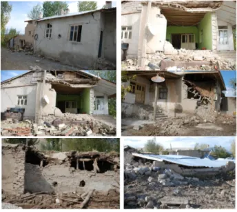
In-plane loaded diaphragms cause out-of-plane effects on the walls in their vicinity. Damages that occur in diaphragms do not greatly affect vertical structural load capacity. Flexible slab diaphragms act as high beams running between walls. In-plane rotations at the edge of diaphragms cause damage at the corners of the walls. If a good load transfer does not exist between the diaphragm and the walls, the longitudinal bending that occurs especially in narrow and tall buildings will push the corner of the diaphragm wall since it cannot be transferred to the shorter side of the wall [20]. In Figure 5 below, examples of damage in masonry structures are presented.
Figure 5: Damage examples in masonry structures.
4 Results and recommendations
In the current situation, many masonry structures exist in Turkey and the construction of these structures are expected to continue. However, if the current construction practices are followed, the same scenes of destruction will probably repeat themselves after every earthquake. For this reason:
• Existing masonry structure stock should be checked using one of the rapid scanning methods; buildings recognized as inadequate should be demolished and reconstructed, and others should be evaluated for either demolition or strengthening.
• Masonry buildings, which are still inadequate, should immediately be repaired and strengthened to counter the risk of a possible earthquake. • The methods of strengthening of these buildings include, after the
installation of steel reinforcement mesh in the masonry wall and anchoring the walls with certain spacing, applying jetcrete to the masonry wall, strengthening with steel lacing, and strengthening with FRP elements. The most feasible and suitable of these methods should be selected and applied, thus, strengthening the structure.
• New masonry structure constructions should comply with masonry structures’ earthquake regulations.
References
[1] Kuban, D., Architectural Concepts, Structure Industry Center Publications, İstanbul, 1990 (Turkish)
[2] Akdemir, Z. and Korkmaz, E., Materials effect to roof and side establishment in Traditional Housing Tissues: The Case of the Western Black Sea Region. 5th National Symposium on Roofing and Facade, 15-16 Nisan, İzmir, 2010 (Turkish)
[3] Budak, A., Uysal, A. and Aydın, C.A., Behavior of Rural Buildings Against Earthquakes, Atatürk University, Faculty of Engineering, Department of Civil Engineering, 25240, Erzurum, 2003 (Turkish)
[4] Ünay, A., Earthquake Resistance of Historical Structures, ODTU Faculty of Architecture Publications, 2002 (Turkish)
[5] Çelebi, R., A Study on Methods of Making and Using Adobe. Associate Professor Thesis, İstanbul, 1979 (Turkish)
[6] Koçu, N., Sustainable Material; Adobe ve Roof-Side Applications (Example of Konya-Çavuş). 6. National Roof & Side Symposium, 12-13 April, Uludağ University Faculty of Engineering and Architecture Görükle Campus, Bursa, 2012 (Turkish)
[7] Erberik, M.A., Vulnerability of Masonry Structures in Turkey. Sixth National Conference on Earthquake Engineering, 16-20 October, Istanbul, 2007
[8] Wasti, S.T., Erberik, M.A., Kaur, C. and Sucuoğlu, H., Study of Earthquake Damaged Repair and Strengthening of Masonry Buildings in Dinar. 4th
National Conference on Earthquake Engineering, 17-19 September, ODTU
Congress and Culture Center, Ankara, 1997 (Turkish)
[9] Basgelen, N., Walls Through The Ages in Anatolia, Archaeology and Art Publications, İstanbul, 1993 (Turkish)
[10] Berker, M., Protection Practices in Wood Architectural Monuments
Related to the Proposal for a Method. MSÜ Institute of Science,
Unpublished PhD Thesis, pp. 385, 1982 (Turkish)
[11] Kahyaoğlu, Ö., Building Science-Rough Construction Works, Ministry of Public Works and Technical Manuals, İstanbul, pp. 11-55, 1985(Turkish) [12] Baycan, A., Master Degree Thesis, Damage Detection and Evaluation of
Masonry Structures, 2004 (Turkish)
[13] Gür, N.V., Deniz, Ö.Ş. and Ekinci, S., Masonry Materials and Components for Masonry Walls Structures. 6. National Roofing & Side Symposium, 12-13 April, Uludağ University Faculty of Engineering and Architecture Görükle Campus, Bursa, 2012 (Turkish)
[14] Bayraktar, A., Türker, T., Altunışık, A.C. and Sevim, B., Determining the Effect of Seismic Behaviour of Masonry Buildings Analytical Model Improvement. International Earthquake Symposium, Kocaeli, 2007 (Turkish)
[15] Önal, M.M. and Koçak, A., Methods for Building Damage Repair and Strengthening of Masonry Details. Congress on Civil Engineering
Problems in Antalya Region, Antalya, Cilt 1, pp. 88-102, 2005 (Turkish)
[16] Sorguç, D., Responsibilities Arising From the Earthquake Damage to
Construction and Repair and Strengthening of Damaged Buildings,
İstanbul Chamber of Commerce Publications , No 2000-45, İstanbul, 2000 (Turkish)
[17] Bruneau, M., Building Damage From the Marmara, Turkey Earthquake of August 17, 1999, Journal of Seismology, Kluwer Academic Publishers, Netherlands, 6; pp. 357-377, 2002
[18] Ural, A., Wrapped and Traditional Type Masonry Structures Investigation of Seismic Behavior. Earthquake Symposium Kocaeli, pp. 89, 2005 (Turkish)
[19] Mertol, A. and Mertol, H.C., (eds). Earthquake Engineering, Earthquake
Resistant Design, Kozan Ofset, Ankara, 2002 (Turkish)
[20] Altan, M, Eren, İ and Güler, K, Status of Damage on the Impact of Masonry Wall Organisations of analysis in some of the masonry buildings Dinar Earthquake 1995. 4th National Conference on Earthquake
Engineering, 17–19 September, ODTU Congress and Culture Center,
Ankara, 1997 (Turkish)
[21] Bruneau, M., Earthquake Response of unreinforced masonry buildings on the Last Status Report, Journal of Structural Engineering, ASCE, 120(1), pp. 231-251, 1994 (Turkish)
![Figure 4: Typical diagonal cracks in masonry structures [17]. 3.2 Damage types in masonry structures](https://thumb-eu.123doks.com/thumbv2/9libnet/3590367.20247/6.663.146.493.213.333/figure-typical-diagonal-masonry-structures-damage-masonry-structures.webp)