Contact imaging in the atomic force microscope using a higher order
flexural mode combined with a new sensor
S. C. Minne, S. R. Manalis, A. Atalar,a)and C. F. Quateb)
E. L. Ginzton Laboratory, Stanford University, Stanford, California 94305-4085 ~Received 4 December 1995; accepted for publication 2 January 1996!
Using an atomic force microscope~AFM! with a silicon cantilever partially covered with a layer of zinc oxide ~ZnO!, we have imaged in the constant force mode by employing the ZnO as both a sensor and actuator. The cantilever deflection is determined by driving the ZnO at the second mechanical resonance while the tip is in contact with the sample. As the tip-sample force varies, the mechanical boundary condition of the oscillating cantilever is altered, and the ZnO electrical admittance is changed. Constant force is obtained by offsetting the ZnO drive so that the admittance remains constant. We have also used the ZnO as an actuator and sensor for imaging in the intermittent contact mode. In both modes, images produced by using the ZnO as a sensor are compared to images acquired with a piezoresistive sensor. © 1996 American Institute of Physics.
@S0003-6951~96!02510-1#
There has been recent effort toward the development of atomic force microscope ~AFM! cantilevers which contain integrated sensors and integrated actuators. The integrated sensor allows operation of the AFM in situations where ex-ternal optical deflection would be cumbersome, namely UHV1 environments and extension of the AFM to parallel operation.2Tortonese3has used the piezoresistor as a sensor for AFM imaging. Takata4has used changes in impedance of a piezoelectric for dynamic AFM imaging. Hsu5 used the same effect for imaging with a near-field scanning optical microscope.
The integrated actuator has been worked on by many groups. Itoh6reported on a single cantilever with two piezo-electric films of zinc oxide~ZnO!, one film for the detector and the second for the actuator for use in the dynamic mode. Fujii7 has used lead Zirconate Titanate ~PZT! films on a single cantilever in conjunction with an optical sensor. Takata8 has imaged with a piezoelectric bimorph for both sensing and actuation in the dynamic mode. Recently we reported construction of an AFM cantilever with an inte-grated piezoresistive sensor and inteinte-grated piezoelectric ac-tuator for use in the constant force mode.9 The integrated actuator improves the performance of the microscope by eliminating the need for an external z-axis actuator during scanning, provides a means for feedback during parallel probe operation, and increases the imaging bandwidth.10
In this letter, we report on a new method for constant force imaging in which a silicon cantilever, partially covered with a single film of ZnO~as described in Ref. 9!, is used as both an actuator and a sensor. In this mode the same canti-lever and experimental configuration can be used for both static and dynamic applications. By employing the ZnO as both an actuator and a sensor, the design of our cantilever can be significantly simplified by eliminating the need for the piezoresistor.
The cantilever consists of a rigid actuator supporting a flexible subcantilever which interacts with the surface ~see
Fig. 1!. The base of the cantilever is the ZnO actuator and this region is roughly 10 times stiffer than the cantilever extension. The extension that is attached to the cantilever can be made of any material. In our design it is silicon with a built-in piezoresistor.11 This geometry provides the versatil-ity of a robust actuator and a soft cantilever for probing the surface of the sample.
Our method for constant force imaging is based on the second resonance of the cantilever. The first, or fundamental, resonance produces the maximum displacement at the tip and is normally used for intermittent, or noncontact imaging. The second resonance is a flexural mode with a node at the tip, and does not appear when the tip of the cantilever is free. When the tip is placed in contact with a surface, the second resonance appears and its amplitude varies as a function of force. The vibrating tip in contact with the surface transmits energy into the sample to a degree that depends on the aver-age force that the tip exerts on the sample. The power dissi-pated by the tip is easily measured by monitoring the current into the ZnO film. Since the drive voltage is constant the current is proportional to the ZnO admittance. The
admit-a!On leave from: Bilkent University, Ankara, Turkey. b!Electronic mail: [email protected]
FIG. 1. Schematic diagram of the experimental setup. When using the ZnO as both the sensor and actuator, the relevant electronics are shown in the dashed box labeled ‘‘Admittance Image’’. The dashed box labeled ‘‘Piezore-sistor Image’’ represents the electronics for using the piezore‘‘Piezore-sistor as the sensor.
1427 Appl. Phys. Lett. 68 (10), 4 March 1996 0003-6951/96/68(10)/1427/3/$10.00 © 1996 American Institute of Physics
tance will vary as the quality of the resonance changes in order to conserve power between the electrical and mechani-cal systems. This admittance variation is used for the deflec-tion signal in the feedback loop.
Figure 1 is a schematic of our experimental setup. When using the ZnO as both the sensor and actuator the relevant electronics are shown in the dashed box labeled ‘‘ZnO Ad-mittance’’. The dashed box labeled ‘‘Piezoresistor’’ are the electronics for using the piezoresistor as the sensor. A com-parison of the piezoresistive signals and the ZnO signals is presented later.
Figure 2~a! is a plot of piezoresistor amplitude versus ZnO drive frequency for various tip sample spacings. The line in the lowest part of the plot correspond to the tip being far away from the sample. As the lines progress upward, the tip is moved towards the sample by 150 Å per line. The resonant peak at 132 kHz represents the third mode of the cantilever. As the tip moves towards the sample the ampli-tude is reduced because the tip intermittently strikes the sample. This can be seen in the middle region of Fig. 2~a!. The resonance at 132 kHz vanishes completely when the tip comes into contact with the surface for the entire cycle. At this point, the boundary condition at the end of the cantilever changes from a free unrestricted movement to constrained motion due to the Hertzian contact with the surface.12 This change creates a second resonance at 102 kHz. Increasing force after tip/sample contact changes the amplitude, the Q of the resonance, and the resonant frequency.
Figure 2~b! is the same plot as Fig. 2~a! except the
ad-mittance of the ZnO is measured rather than the stress in the piezoresistor. The coupling between the mechanical system and the ZnO is greater at higher order modes due to the increased curvature in the ZnO. This allows us to monitor changes in the ZnO admittance at higher order modes, which was not possible at the fundamental. In Fig. 2~b! the varia-tion at 120 kHz is an external electromagnetic interference signal that is picked up by interconnecting wires, and is un-related to the cantilever.
Figure 2~c! shows the fundamental, or first, resonance of the cantilever measured with the piezoresistor at 35.5 kHz. We note that the fundamental resonance can be used for in-termittent contact imaging with the piezoresistor as a sensor and the ZnO as an actuator.
To examine the degree of change in the resonant peaks with force we excite the ZnO at a given resonance, use a lock in amplifier to measure the piezoresistor and the ZnO admit-tance, and vary the tip sample spacing. The results are pre-sented in Fig. 3 as standard force curves. In Fig. 3 negative tip sample distances represent the tip out of contact with the sample. The sharp dip in the force curves corresponds to sticking due to the meniscus between the tip and sample. Minimum detectable deflection interprets the signal to noise information contained in the curves of Fig. 3, and is pre-sented in the following section.
Figure 3~a! was performed with an excitation of 132 kHz
~third order mode! and a tip amplitude of 1000 Å ~0.1 V to
ZnO!. The admittance is detected by measuring a current through a 10 kV resistor in series with the ZnO, and corre-sponds to the cantilever deflection. The form of this curve suggests an intermittent contact mode. There is no change in admittance while the tip is far from the sample. As the tip approaches, it begins to strike the surface, and the amplitude of the resonance decreases. Once the tip is in complete con-tact with the surface, the admittance no longer changes.
In Fig. 3~b! the cantilever was excited at the second ~102 kHz! resonance, with the ZnO drive again at 0.1 V, and the ZnO admittance was monitored. The form of this curve sug-gests a contact mode. When the tip is away from the sample the response is zero. Once the tip contacts the surface the response increases due to the increased amplitude of the
FIG. 2. Plot of the second and third resonant frequencies using the ~a! piezoresistor and~b! zinc oxide for different tip sample spacing. Each line in the plot represents a 150 Å movement of the tip towards the sample. Curves at the bottom of the plot represent no contact while curves at the top repre-sent complete contact.~c! Plot of the fundamental resonant frequency using the piezoresistive sensor.
FIG. 3. Force curves for~a! intermittent contact with the zinc oxide as a sensor,~b! contact with the zinc oxide as a sensor, ~c! intermittent contact with the piezoresistor as a sensor, ~d! contact with the piezoresistor as a sensor. Negative distances represent the tip out of contact with the sample.
resonance. Since there is no resonance present at 102 kHz when the tip is away from the sample, an excitation of 0.1 V to the ZnO causes only a 30 Å deflection at the tip. The range of the force curve shown extends over 2000 Å, which is considerably greater than the on, or off, resonance amplitude of the tip. This indicates that this is truly a contact mode, not a modified intermittent contact mode.
Figures 3~c! and 3~d! correspond to measurements taken in the same manner as Figs. 3~a! and 3~b! except the piezore-sistor is used as the sensor instead of the ZnO. From the traces in Fig. 3, it is apparent that the noise in the piezore-sistor ~PR! traces @Figs. 3~c! and 3~d!# is less than the noise in the ZnO traces@Figs. 3~a! and 3~b!# for both intermittent contact and contact modes. The minimum detectable deflec-tion, where the cantilever response corresponds to the rms noise, for the four modes in a 100 Hz bandwidth are: ~a! intermittent contact/ZnO530 Å, ~b! contact/ZnO540 Å, ~c! intermittent contact/PR520 Å, ~d! contact/PR530 Å. The minimum detectable deflection for intermittent contact using the fundamental mode and dc constant force are 10 Å in a 100 Hz bandwidth.
In the design of this initial cantilever we were planning to use the ZnO only as an actuator, and did not anticipate its
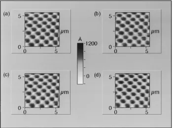
use as a sensor. In order to facilitate the process of fabrica-tion, we designed the ZnO film in such a way that the major portion covered the die with a minor portion covering the cantilever. The major portion, of course, is insensitive to can-tilever vibration. The area of the film on the die is 26 times larger than the area of the film on the cantilever. It is feasible in a new design to eliminate most of the film on the die and this should improve the sensitivity by an order of magnitude. Images are readily obtained from these four new probing techniques, and are presented in Fig. 4. The images in Fig. 4 are in the same order as that of Fig. 3: ~a! intermittent contact/ZnO, ~b! contact/ZnO, ~c! intermittent contact/PR,
~d! contact/PR. The sample is a two-dimensional gold
grat-ing with a period of 1mm and height of 1000 Å. All of the images were taken with feedback to the ZnO actuator.
We would like to thank Babur Hadimioglu and Jim Zesch at Xerox PARC for the ZnO films. The primary sup-port for this work came from the Joint Services Electronics Program N00014-91-J-1050 of the Office of Naval Research with partial support from NSF. S.C.M. acknowledges the support of the Leland T. Edwards Fellowship and S.R.M. acknowledges the support of the Urbanek Fellowship.
1F. J. Giessibl, Science 267, 68~1995!.
2S. C. Minne, P. Flueckiger, H. T. Soh, and C. F. Quate, J. Vac. Sci.
Tech-nol. B 13, 1380~1995!.
3M. Tortonese, H. Yamada, R. C. Barrett, and C. F. Quate, in Proceedings
of Transducers ’91, IEEE publication 91 CH2817-5, p. 448~1991!.
4K. Takata, Jpn. J. Appl. Phys. 32, 2455~1993!.
5J. W. P. Hsu, M. Lee, and B. S. Deaver, Rev. Sci. Instrum. 66, 3177
~1995!.
6
T. Itoh and T. Suga, in Proceedings of Transducers’95, Stockholm, Sweden
~Royal Swedish Academy of Engineering Science IVA, Stockholm, 1995!,
p. 632.
7T. Fujii, S. Watanabe, M. Suzuki, and T. Fujiu, J. Vac. Sci. Technol. B 13,
1119~1995!.
8
K. Takata, Rev. Sci. Instrum. 64, 2598~1993!.
9S. C. Minne, S. R. Manalis, and C. F. Quate, Appl. Phys. Lett. 67, 3918
~1995!.
10S. R. Manalis, S. C. Minne, and C. F. Quate~unpublished!. 11
This resistor can be used as a piezoresistor for an alternative method of sensing deflection, but since we now use the ZnO as both the sensor and actuator, the silicon resistor is free to be used as a bias path for lithogra-phy, heating, or tunneling in future experiments.
12K. L. Johnson, Contact Mechanics~Cambridge University Press,
Cam-bridge, England, 1985!. FIG. 4. Images taken in ~a! intermittent contact with the zinc oxide as a
sensor,~b! contact with the zinc oxide as a sensor, ~c! intermittent contact with the piezoresistor as a sensor, ~d! contact with the piezoresistor as a sensor. In all images feedback to the ZnO actuator was used.
1429