CHEMISTRY AND STRUCTURE
OF SPUTTER DEPOSITED
BORON-CARBON-NITROGEN
THIN FILMS
A DISSERTATION
SUBMITTED TO THE DEPARTMENT OF CHEMISTRY
AND THE GRADUATE SCHOOL OF ENGINEERING AND
SCIENCE
OF BILKENT UNIVERSITY
IN PARTIAL FULLFILMENT OF THE REQUIREMENTS
FOR THE DEGREE OF
DOCTOR OF PHILOSOPHY
By
Mustafa Fatih GeniĢel
January, 2012
II
I certified that I have read this thesis and that in my opinion it is fully adequate, in scope and quality, as dissertation for the degree of doctor of philosophy.
_______________________________ Assist. Prof. Dr. Erman Bengü (Advisor)
I certified that I have read this thesis and that in my opinion it is fully adequate, in scope and quality, as dissertation for the degree of doctor of philosophy.
_______________________________ Prof. Dr. Servet Turan
I certified that I have read this thesis and that in my opinion it is fully adequate, in scope and quality, as dissertation for the degree of doctor of philosophy.
_______________________________ Prof. Dr. Ömer Dağ
III
I certified that I have read this thesis and that in my opinion it is fully adequate, in scope and quality, as dissertation for the degree of doctor of philosophy.
_______________________________ Assoc. Prof. Dr. Oğuz Gülseren
I certified that I have read this thesis and that in my opinion it is fully adequate, in scope and quality, as dissertation for the degree of doctor of philosophy.
_______________________________ Assist. Prof. Dr. Emrah Özensoy
Approved by Graduate school of Engineering and Science
_______________________________
IV
ABSTRACT
CHEMISTRY AND STRUCTURE OF SPUTTER
DEPOSITED BORON-CARBON-NITROGEN THIN
FILMS
Mustafa Fatih GeniĢel
PhD. in Chemistry
Supervisor: Assist. Prof. Dr. Erman Bengü
There is a growing interest in synthesizing new materials with unique mechanical properties like hardness or electrical and optical properties. For this purpose, Boron-Carbon-Nitrogen (BCN) ternary phase diagram promises new materials with potentially unique properties, such as variable band gap semiconductors or phases with extreme hardness. On the other hand, the physical or mechanical properties of these new BCN materials strongly depend on the chemical environment of the atoms and their atomic structure. In this thesis, atomic structure and chemical environment of the atoms in BCN thin films were investigated. BCN films were synthesized by Reactive Magnetron Sputtering (RMS) technique from a B4C target. Various process parameters of
synthesis were changed during deposition, such as the substrate bias, substrate-to-target distance and N2 flow.
The effect of process parameters are investigated with respect to their fundamental effects on the growing BCN films. Several sets of experiments were planned and conducted in order to gain insight as per their effect on the final chemistry and atomic structure. The characterization of the chemical composition of the films was done using data from Infrared Spectroscopy,
V
Raman Spectroscopy, X-ray Photoelectron Spectroscopy, X-Ray Diffraction, and Electron Energy Loss Spectroscopy. Also, electron transparent thin cross-sections from the BCN films were prepared using focused-ion beam technique for conducting High Resolution Transmission Electron Microscopy analysis for the verification of atomic structure.
In the first series, named B series, the energy is supplied to growing film by applying a radio frequency generated d.c. bias on the substrate. Magnitude of the applied bias was changed throughout the series. In the second and third series, namely P and D series, the effect of substrate-to-target distance was investigated. In these series, BCN and BN films were deposited on substrates that were located at different distances from the target surface. In sub-series, effect of, i) the magnitude of applied bias, ii) type of applied substrate bias on the chemistry of the BCN films were scrutinized. In addition, the effect of atomic composition on the bonding preferences was studied. For this purpose, a series of BCN films were r.f. sputter deposited from B4C target with different
N2 flow rate at the process gas.
After the careful analysis of the data from mainly the spectroscopic techniques, several important results were obtained. First, a prevailing bonding preference, i.e. phase segregation, was observed in the films deposited regardless of the process parameters used, such that a dominant presence of B-N and C-C or C-N bonding were observed in the films. Furthermore, increasing the substrate bias or decreasing the substrate-to-target distance resulted in the atomic ordering and layered (turbostratic) BCN films. Examination of the spectroscopic data in detail also indicated that the individual layers were made out of separate domains of h-BN like and graphitic like carbon regions, which supports the phase-segregation assertion.
VI
Two main regimes are identified for the growth of BCN films; thermodynamically or kinetically controlled regimes. BCN films synthesized with large substrate bias or close to target surface were overall more ordered as the adatoms arriving on the substrate surface had enough energy to diffuse and find energetically most favorable sites. Such a case could be termed as thermodynamically controlled regime. In the opposite case, where adatoms were in a diffusion-limited environment, the final chemistry and structure was dictated by the kinetics. However, the prevalence of B-N bonding in both cases, and failure to observe hybridized chemistry suggests that bonding energy consideration is the major deciding factor for the chemistry of BCN films.
As a conclusion, the work presented herein suggests that phase segregation in BCN films reveal as an innate character, while hybridization is not observed in the process parameter space explored. The main reason for this is the relative energies of the B-N and C-C bonding.
Key words: Boron Carbon Nitrogen, Thin Film, Reactive Sputter Depositions, XPS, IR, Raman Spectroscopy, Biasing, r.f. sputtering, B4C
VII
ÖZ
SAÇTIRMA BĠRĠKTĠRME YÖNTEMĠ ĠLE ELDE
EDĠLEN BOR-KARBON-AZOT ĠNCE FĠLMLERĠN
KĠMYASI VE YAPISI
Mustafa Fatih GeniĢel PhD. Kimya
DanıĢman: Yrd. Doç. Dr. Erman Bengü
EĢsiz elektriksel, optik veya mekanik özelliklere sahip yeni malzeme sentezine ilgi büyümektedir. Bor-Karbon-Azot (BCN) üçlü faz diyagramı potansiyel olarak benzersiz özelliklere sahip, değiĢken band aralığına sahip yarı iletkenler veya çok sert fazlar gibi yeni malzemeler vaat etmektedir. Diğer yandan, bu yeni BCN temelli malzemelerin fiziksel ve mekanik özellikleri malzemedeki atomların kimyasal çevresine ve atomik yapısına bağlıdır. Bu tezde, B4C
hedeften reaktif magnetronlu saçtırma (RMS) tekniği ile sentezlen BCN filmlerdeki atomların bağ yapıları ve kimyasal çevreleri araĢtırılmıĢtır. Biriktirme sırasında farklı iĢlem parametreleri değiĢtirilerek, örneğin alttaĢ meyillendirmesi, alttaĢ-hedef mesafesi ve N2 akıĢ miktarı gibi, bunların
sentezlenen filmin özelliklerine etkisi incelenmiĢtir.
ĠĢlem sırasında kullanılan parametrelerin kimyasal ve atomik yapı üzerine nihai etkisini anlamak için birçok deney seti planlanıp ve uygulanmıĢtır. Filmlerdeki kimyasal çevrenin karakterizasyonu için, Kızılötesi Spektroskopisi, Raman Spektroskopisi, X-ıĢını Fotoelektron Spektroskopisi, X-ıĢını Kırınımı ve Elektron Enerjisi Kayıp Spektroskopisi kullanılmıĢtır. Ayrıca, yapıdaki atomik
VIII
değiĢiklikler için, OdaklanmıĢ Ġyon Demeti tekniği ile hazırlanan, elektron geçirgen, ince, yan kesit BCN örnekleri Yüksek Çözünürlüklü Geçirgenli Elektron Mikroskopu`nda incelenmiĢtir.
B serisi olarak isimlendirilen ilk deney serisinde, alttaĢ üzerinde büyümekte olan filme enerji, alttaĢa uygulanan radyo frekansı ile oluĢturulmuĢ doğrusal akım meyillendirmesi ile sağlandı. Uygulanan meyillendirmenin Ģiddeti seri içinde belli bir aralıkta değiĢtirilmiĢtir. P ve D serisi olarak isimlendirilen ikinci ve üçüncü serilerde, alttaĢ-hedef mesafesinin etkisi incelendi. Bu serilerde BCN ve BN filmler hedefin yüzeyine göre değiĢik mesafelere yerleĢtirilen alttaĢlar üzerine biriktirilmiĢtir. Bu serilerin alt-serilerinde ise alttaĢa uygulanan meyillendirmenin Ģiddeti ve tipinin BCN filmlerin kimyasına etkisi detaylı olarak incelenmiĢtir. Ayrıca, G serisinde de atomik kompozisyonun bağlanma tercihleri üzerine etkisi çalıĢıldı. Bu seride değiĢik miktarda N2 içeren çalıĢma
gazı akıĢı altında radyo frekansı saçtırmasında tabii tutulan B4C hedeften
değiĢik uzaklıklara yerleĢtirilen alttaĢlar üzerine BCN filmler biriktirilmiĢtir. Yukarıda bahsedilen serilerden sentezlenen BCN filmlerde çoğunluğu spektroskopik tekniklerle elde edilen bilgiler dikkatlice analiz edildikten sonra birçok önemli sonuç elde edilmiĢtir. Ġlk olarak, biriktirilen filmlerde kullanılan iĢlem parametrelerinden bağımsız bir Ģekilde bağlanma tercihinin faz ayrıĢmasından yana olduğu gözlemlenmiĢtir. Örneğin, filmlerde baskın biçimde B-N ve C-C veya C-N bağları gözlemlenmiĢtir. Ayrıca, uygulanan alttaĢ meyillendirmesinin arttırılması veya alttaĢ-hedef mesafesinin azaltılmasının BCN filmlerde atomik düzenliliği arttırarak ve tabakalı (turbostratic) BCN yapısının gözlemlenmesine yol açmıĢtır. Spektroskopik datanın detaylı incelenmesi de; herbir tabaka ayrıĢmıĢ h-BN ve grafitik karbon benzeri kümeler içeren bölgelerden oluĢtuğunu, bu durumun ise faz ayrıĢması iddiasını desteklediğini göstermiĢtir.
IX
BCN filmlerin büyümesinde, termodinamik ve kinetik olarak kontrol edilen iki ana rejim tanımlanmıĢtır. Yüksek alttaĢ meyillendirmesi ile veya hedef yüzeyine yakın alttaĢlar üzerinde sentezlenen BCN filmlerin atomik yapısı genel olarak daha düzenlidir. Buna neden olarak alttaĢa ulaĢan iyonların yüzeyde film büyümesine katılan saçtırılmıĢ ve eklemlenen atomlara, enerji olarak en uygun pozisyonu yüzeyde bulmaları için gerekli enerjiyi sağlaması gösterilebilir. Bu ve benzer durumlara termodinamik olarak kontrol edilen rejim denilebilir. Tam aksi durumda ise, eklemlenen atomların yüzeydeki hareketlerinin sınırlandırıldığı rejim, elde edilen son kimya ve yapı kinetik tarafından belirlenmiĢtir. Ancak, her iki durumda da egemen olan B-N bağı ve melezlenmiĢ kimyanın gözlemlenmemesi, BCN filmlerde bağlanma enerjisinin belirleyici ana unsur olduğunu iĢaret etmektedir.
Sonuç olarak; sunulan çalıĢma, uygulanan iĢlem parametresi uzayı veya kümesinde, faz ayrıĢmasının BCN filmler için tabii bir karakter olduğunu ve melezlenmenin mümkün olmadığını ileri sürmektedir. Bunun temel nedeni, B-N ve C-C bağlarının görece kararlılığı ve enerjisidir.
Anahtar Kelimeler: Bor Karbon Azot, Ġnce Film, Reaktif Saçtırmalı Biriktirme, XPS, IR, Raman Spektroskopisi, Meyillendirme, r.f. Saçtırma, B4C
X
XI
ACKNOWLEDGEMENT
I would like to thank my advisor, Assist. Prof. Dr. Erman BENGÜ for his supervision and encouragement throughout this research.
I am thankful to Prof. Dr. Servet TURAN and Hilmi YURDAKUL for their help with the TEM study. I am also thankful to Prof. Dr. Oğuz GÜLSEREN and Dr. Rasim Volga OVALI for the theoretical calculations. I wish to thank Prof. Dr. RaĢit TURAN and Mustafa Kulakçı for their assistance during the ion implantation experiments.
I would like to also extend my thank to current and previous Bengü-Lab members: Gökçe KÜÇÜKAYAN, Beril BAYKAL, Hüseyin ALAGÖZ, Dr. Kuldeep RANA, Dr. Md. Nizam UDDIN and Dr. Ebru Devrim SAM.
I would like to express my appreciation to my dear friends for their unrelenting moral support: Zafer SAY, Cüneyt KARAKAYA, Aslı Melike SOYLU, Cemal ALBAYRAK, Hacı Osman GÜVENÇ, Yurdanur TÜRKER, Hikmet SEZEN, Müge ARTAR, Eda ÖZKARAOĞLU, ġeyma EKĠZ, ġeyma ÖZTÜRK, Fatma PĠR, Emrah PARMAK, Vüsala ĠBRAHĠMOVA. Also special thanks to Ethem ANBER and Emine YĠĞĠT.
Finally, I would like to express my deepest gratitude toward my family and my beloved wife Neslihan GENĠġEL.
XII
TABLE OF CONTENTS
1. INTRODUCTION ... 1
1.1 Literature Review: BCN Thin Film Synthesis ... 11
1.1.1. Chemical Vapor Deposition (CVD) ... 11
1.1.2. Ion Beam Assisted Deposition (IBAD) ... 14
1.1.3 Pulsed Laser Deposition (PLD) ... 17
1.1.4. Magnetron Sputtering (MS) ... 18
1.2. Literature Review: Characterization Techniques ... 26
1.2.1 Infrared Spectroscopy (IR) ... 26
1.2.2. Raman Spectroscopy ... 28
1.2.3 X-Ray Photoelectron Spectroscopy (XPS) ... 31
1.2.4 X-Ray Diffraction (XRD) ... 35
1.2.5 Transmission Electron Microscopy (TEM) ... 37
2. EXPERIMENTAL ... 39
2.1 Equipment ... 39
2.1.1 Deposition and Synthesis Equipment ... 39
2.1.2 Characterization Techniques and Equipment... 42
2.2 Experimental Procedure ... 46
2.2.1. Effect of Bias (B Series) ... 49
2.2.2. Effect of the type of bias applied to substrate and target to substrate distance (P Series) ... 49
2.2.3. Effect of the substrate-to -target distance (D series) ... 50
2.2.4. Effect of reactive gas flow rate (G series) ... 52
3. RESULTS and DISCUSSION ... 53
3.1. Investigation of the effect of ion bombardment on the atomic structure and chemistry of BCN thin films ... 55
3.1.1. B series ... 56
XIII
3.1.3 D Series ... 96
3.1.4. Summary of B, P and D Series ... 127
3.2. Investigation of the effect of nitrogen amount on the atomic structure and chemistry of BCN thin films ... 129
3.2.1. G series ... 129
4. CONCLUSION ... 149
REFERENCES ... 152
APPENDIX ... 171
A.1 Thin Film Technology ... 171
A.2 Physical Vapor Deposition (PVD) ... 171
A.2.1 Plasma ... 172
A.2.2 Particles- Surface Interaction and Sputtering ... 175
A.2.3Thin Film Growth and Deposition ... 178
A.3 Magnetrons ... 184
A.4 Vacuum Environment and Mean Free Path Phenomena ... 186
XIV
LIST OF FIGURES
Figure 1: Ternary phase diagram of Boron, Carbon and Nitrogen ... 3
Figure 2: Crystal structure of (a) c-BN and (b) diamond. ... 4
Figure 3: Crystal structure of (a) h-BN and (b) graphite. ... 5
Figure 4: Layered h-BC2N structures that are considered by Liu et al.. ... 6
Figure 5: Number of BCN related publications vs. publication year. Three main periods are observed; region I motivated by c-BN and β-C3N4, region 2 stagnation period, and region III the onset of graphene and other 2-D structures era. (Data obtained from Web of Science) ... 7
Figure 6: Schematic representation of PECVD. ... 12
Figure 7: Schematic representation of an electron beam evaporator. ... 15
Figure 8: Schematic representation of IBAD. ... 15
Figure 9: Schematic representation of PAPLD. ... 18
Figure 10: Schematic representation of reactive sputter deposition technique. . 19
Figure 11: Schematic representation of D and G vibration modes for carbonaceous materials. ... 30
Figure 12: Schematic representation of the alignment of basal planes for turbostratic-BN. ... 38
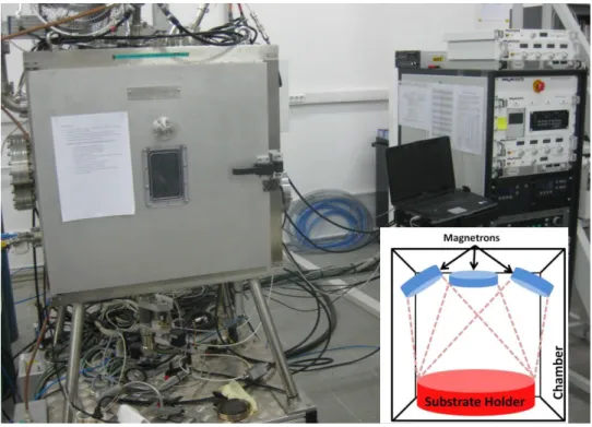
Figure 13: Schematic representation (inset) and photograph of VAKSIS Deposition system. ... 40
Figure 14: Schematic representation of magnetron configuration (inset) and photograph of MANTIS deposition system. ... 42
Figure 15: The experimental design followed in the study is shown in the flow chart. Two major sets of experiments were planned in order to understand a) effect of supplied energy to growing film and b) effect of chemical composition. ... 48
XV
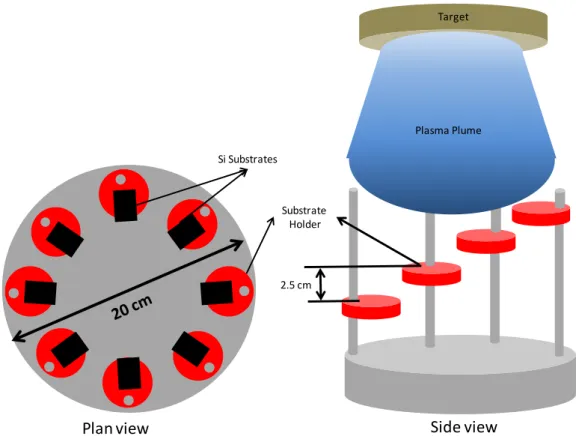
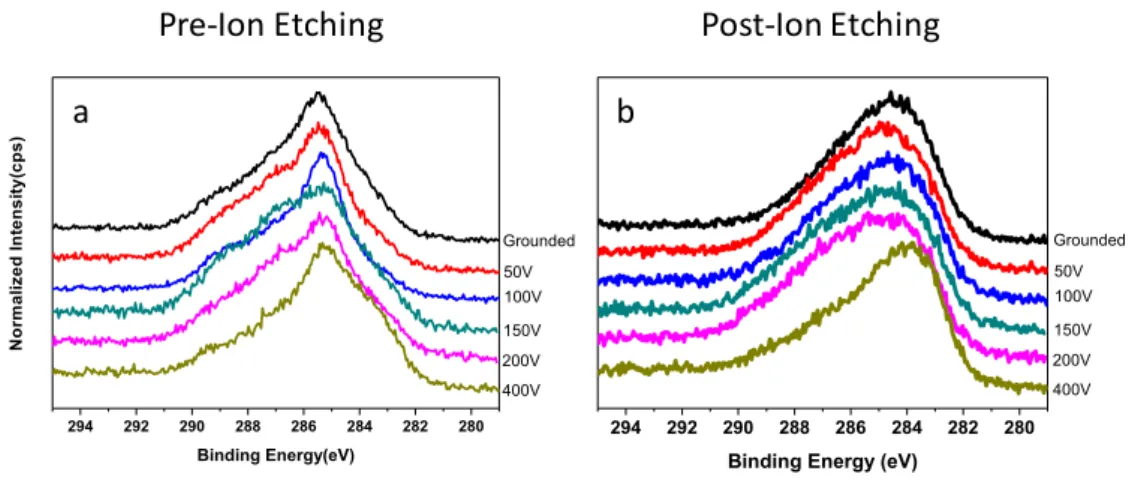
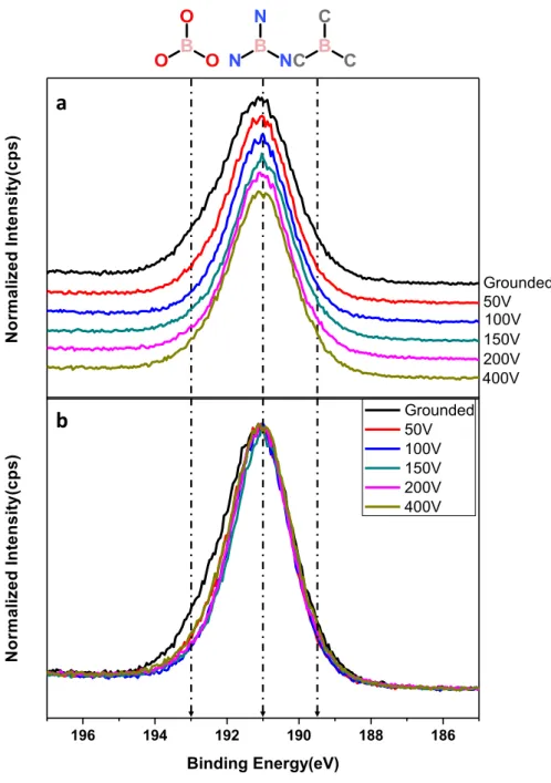
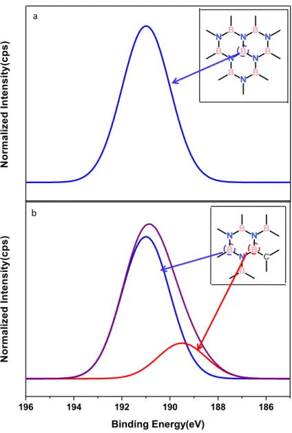
Figure 16: Schematic representation of the substrate holder designed and built for experimental series D. ... 51 Figure 17: Atomic composition of the B series films with respect to applied bias on the substrate during deposition; (a) pre- and, (b) post ion etching obtained from XPS analysis, (c) B:C and B:N atomic ratios after ion-etching. ... 58 Figure 18: The effect of ion etching on the C 1s region from BCN films deposited in B series; (a) pre ion-etching and (b) post ion-etching. (Ion-etching parameters: using Argas, 750 V at 19 µA for 50 sec.) ... 59 Figure 19: XPS spectra of the B 1s region of BCN films deposited on substrate with different r.f. generated d.c. biased in B series, (a) waterfall representation (b) overlap representation. ... 64 Figure 20: Hypothetical XPS spectra for (a) boron in BN environment, (b) carbon coordinated boron in BN environment. Insets show the corresponding atomic configurations. ... 65 Figure 21: XPS spectra of the N 1s region of BCN films deposited on substrate with different r.f. generated d.c. biased in B series, (a) waterfall representation (b) overlap representation. ... 66 Figure 22: XPS spectra of the C 1s region of BCN films deposited on substrate with different r.f. generated d.c. biased in B series, (a) waterfall representation (b) overlap representation. ... 67 Figure 23: IR spectra of BCN film deposited on substrate with different r.f. generated d.c. bias; (a) waterfall representation, (b) overlap representation of the overall spectrum. In (c) and (d) are showing the detailed regions for Band II and Band I, respectively. ... 70 Figure 24: XRD pattern of thin film deposited with -200 V r.f. generated d.c. bias and substrate. ... 76 Figure 25: HRTEM image of BCN film deposited on the grounded substrate and substrate. The squares, defined with dashed lines are the image areas where the FFT process was applied. ... 79 Figure 26: (a) HRTEM image cropped from the substrate region of HRTEM image obtained from grounded sample of B series with (inset a) FFT image of substrate, and (b) HRTEM image cropped from BCN film part of the HRTEM
XVI
image collected from the grounded sample of B series, with (inset b) FFT image of thin film. ... 80 Figure 27: HRTEM image of the film deposited on substrate -200 V r.f. generated d.c. bias and the substrate. ... 81 Figure 28: HRTEM image of the BCN film deposited on -200 V r.f. generated d.c. biased substrate and inset is the FFT of the image. ... 82 Figure 29: HRTEM image of the BCN film that was deposited on -400 V r.f. generated d.c. bias applied substrate. The square defined with dashed lines is the image area where the FFT process was applied. ... 83 Figure 30: HRTEM image cropped from HRTEM image of BCN film deposited on -400 V r.f. generated d.c. biased substrate and inset is the FFT image... 84 Figure 31: Comparison of line plot obtained from of FFT images of -200 V d.c. and -400 V d.c. biased sample in B series... 85 Figure 32: Energy filtered TEM analysis of the BCN film deposited on -400 V biased substrate; (a) Zero energy loss image, (b) HA-ADF image, (c) Boron K edge image, (d) Nitrogen K edge, (e) Carbon K edge, (f) Titanium K edge image. ... 85 Figure 33: EELS spectra of the BCN films in B series; (a) Boron K-edge, (b) Carbon K-edge and (c) Nitrogen K-edge region. ... 87 Figure 34: IR spectra of BCN films deposited on different magnitude p-d.c. biased substrate in P18 series. (Target-to-substrate distance is 18 cm) ... 90 Figure 35: IR spectra of BCN films deposited on, different magnitude and type biased substrate in P8 series. (Target-to-substrate distance is 8 cm) ... 91 Figure 36: Comparison of IR spectra of BCN films deposited with same bias magnitude in P8 and P18 series, (a) Grounded films,(b) -50 V and (c)-100 V p-d.c. biased films... 95 Figure 37: Atomic compositions of the BCND50 series obtained from the XPS data obtained from (a) pre- (b) post- ion etching surfaces and (c) comparison of atomic composition of data in (b). ... 99 Figure 38: XPS spectra of the B 1s region of BCN films deposited on substrate located different substrate-to-target distances in BCND50 series, the substrates
XVII
were -50 V p-d.c. biased. (a) waterfall representation (b) overlap representation. ... 101 Figure 39: XPS spectra of the N 1s region of BCN films deposited on substrate located different substrate-to-target distances in BCND50 series, the substrates were -50 V p-d.c. biased. (a) waterfall representation (b) overlap representation. ... 103 Figure 40: XPS spectra of the C 1s region of BCN films deposited on substrate located different substrate-to-target distances in BCND50 series, the substrates were -50 V p-d.c. biased. (a) waterfall representation (b) overlap representation. ... 104 Figure 41: IR spectra of the BCN films deposited on substrate located different substrate-to-target distances in BCND50 series, the substrates were -50 V p-d.c. biased, (a) water fall representation, (b) overlap representation, (c) focused and normalized Band II region. ... 107 Figure 42: Raman spectra of the BCN films deposited on substrate located different substrate-to-target distances in BCND50 series, the substrates were -50 V p-d.c. biased,... 110 Figure 43: Atomic compositions of the BCN films deposited on substrate located different substrate-to-target distances in BCNDGr series, the substrates were -grounded. the XPS data obtained from (a) post ion etched surface and (b) comparison of the atomic composition. ... 112 Figure 44: IR spectra of the BCN films deposited on substrate located different substrate-to-target distances in BCND50Gr series, the substrates were grounded, (a) water fall representation, (b) overlap representation. Focused and normalized (c) Band II and (d) Band I region. ... 115 Figure 45: Raman spectra of films deposited in BCNDGr series experiments. Substrates were grounded ... 116 Figure 46: IR spectra of the BCN films deposited on substrate located different substrate-to-target distances in BCND50DC series, the substrates were -50 V d.c. biased,(a) waterfall representation, (b) overlap representation, ... 118 Figure 47: Atomic compositions of the BN films deposited in BND series obtained from the XPS data of post ion-etched surface (at 750 eV, 5 min). ... 121
XVIII
Figure 48: IR spectra of the BN films deposited on substrates located at different substrate-to-target distances in BND50 series. All of the substrates were -50 V p-d.c. biased; (a) water fall representation, (b) overlap representation, (c) Band II region and (d) Band I region in focus. ... 124 Figure 49: A comparison of the reference IR spectrum from powered h-BN and BN films deposited on the substrates located 7.5 cm and 25 cm away from the target surface. ... 125 Figure 50: Schematic representation of the interaction between alignment of basal planes in t-BN and the incoming photons. ... 126 Figure 51: The change in the atomic composition with the increasing in N2
amount in flowing gas, (a) pre-ion etched data, (b) post-ion etched data, (c) comparison of the atomic ratios obtained from post ion etched surface. ... 131 Figure 52: XPS spectra of the B 1s region of BCN films deposited with varying N2 flow rate in GT series. During depositions substrates were -50 V p-d.c.
biased and substrates were located 8 cm away from target surface. (a) waterfall representation (b) overlap representation. ... 133 Figure 53: XPS spectra of the N 1s region of BCN films deposited with different N2 flow rate in GT series. During depositions substrates were -50 V
p-d.c. biased and substrates were located 8 cm away from target surface. (a) waterfall representation (b) overlap representation... 135 Figure 54: XPS spectra of the C 1s region of BCN films deposited with different N2 flow rate in GT series. During depositions substrates were -50 V
p-d.c. biased and substrates were located 8 cm away from target surface, (a) waterfall representation (b) overlap representation... 138 Figure 55: IR spectra of the BCN films deposited with different N2 flow rate in
GT series. During depositions substrates were -50 V p-d.c. biased and substrates were located 8 cm away from target surface, (a) waterfall representation, (b) overlap representation. ... 140 Figure 56: Raman spectra of the BCN films deposited with different N2 flow
rate in GT series. During depositions substrates were biased using -50 V p-d.c. and they were located 8 cm away from target surface raw data. ... 142 Figure 57: Raman spectra of the BCN films deposited with N2 flows up to 3%
XIX
Raman spectra of the BCN films deposited with N2 flows 3% and above in GT
series are given in (b) with increasing intensity in the 1000-1600cm-1 region. 143 Figure 58: Raman spectra of the BCN films deposited with different N2 flow
rate in GT series. During depositions substrates were biased using -50 V p-d.c. and they were located 8 cm away from target surface; assigned peak positions for the D and G peak positions for carbon-based materials and c-BN and h-BN are shown. ... 144 Figure 59: IR spectra of the BCN films deposited with different N2 flow rate in
GK series. During depositions substrates were grounded and substrates were located 18 cm away from target surface, (a) waterfall representation, (b) overlap representation, focused and normalized ... 147 Figure 60: Comparison of the IR data of the BCN films between GK (8 cm) and GT (18 cm) series for corresponding N2 flows; (a) % 0, (b) % 1, (c) % 2, (d) %
XX
LIST OF TABLES
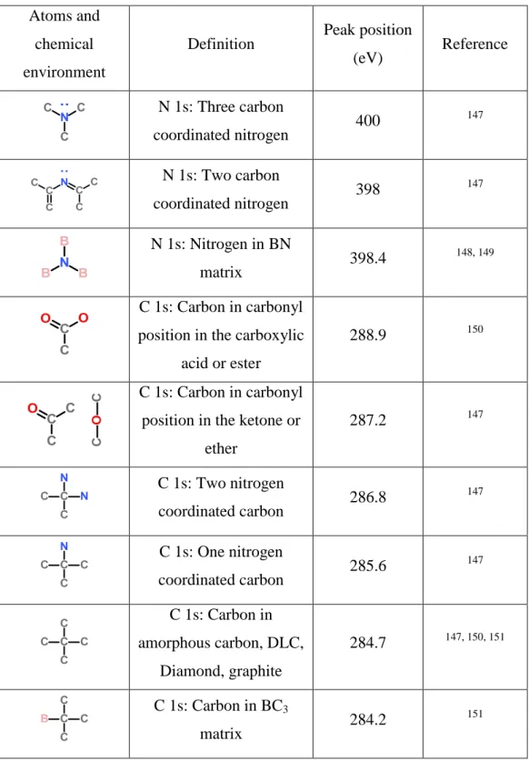
Table 1: IR peak positions for relevant bonds for BCN coatings compiled from literature. ... 27 Table 2: Raman peak positions of relevant bonding for BCN coatings compiled from literature... 29 Table 3: Binding energy list of B 1s, C 1s and N 1s core electrons for various bonding environments acquired from literature. ... 34 Table 4: Deposition parameters that were fixed and kept constant during all of the following experimental series: ... 47 Table 5: Experimental parameters used for the BCND subsets. ... 52 Table 6: Area under the peaks and intensity of bands in the IR spectra of BCN films deposited for B series. ... 71 Table 7: Band areas and intensities of P series IR spectra ... 92
1
1. INTRODUCTION
Thin film technology has been one of the most important fields of science and technology after the advent of semiconductors. One of the earliest reports regarding thin films synthesized under vacuum conditions was made by Drude in 18891. Drude, in his work, reported that he encountered deposits with unusual properties on the walls of glass discharge tubes. This could be suggested as the start of a new area of science; thin film technology.
Major progress in thin films technology was fueled with the advent of vacuum technology following the early 1940’s and gained significant speed since 1960's. This technique allowed for the coverage of large areas using relatively small amounts of material. Therefore, in principle properties of very large areas could be easily altered by the thin films. For example, glass is a good electrical insulator but a few microns thick gold coated glass surface can become as conductive as gold. In addition to this, obtaining metastable phases at low temperatures was another advantage of thin films synthesis. Especially, with plasma involved techniques, like plasma assisted chemical vapor deposition (PACVD) and sputter deposition techniques, thermodynamically metastable phases at room temperature conditions, like diamond and cubic boron nitride, could be synthesized at lower temperatures and pressures than bulk synthesis methods of these materials.
Synthesis of polycrystalline diamond films merit further discussion. The phase diagram of carbon was indicated that for synthesizing diamond high pressures (more than 5GPa) were needed according to Berman-Simon line2. For kinetic purposes of phase transformation, high temperatures (few thousands Kelvin) were also required3. However with the help of activated species created in the
2
plasma environment, polycrystalline diamond films could be synthesized at lower than 1000 K and at 20 mbar pressure using PACVD technique4.
Thin films technology has been applied to multitude of other technologically crucial areas such as semiconductor technology, cutting tool technology, and photovoltaic cell technology5-7. It is well known that compounds between IIIA and VA groups and elemental solids of group IVA (e.g. Si and Ge) are commonly used in the aforementioned technologies for their unique electrical and physical properties. Some of these materials in question display a wide range of range electrical properties, furthermore these materials posses’ distinct physical properties, such as high hardness and optical transparency. One of the reasons for these unique properties is the highly covalent character and short bond lengths between the basic building blocks (atoms) for these materials.
One example for the application area of thin films technology is the synthesis of compounds and elemental solids in the B-C-N ternary system. The ternary compounds that are composed of boron, carbon, and nitrogen atoms can be called BCN compounds. The importance of these ternary compounds could be seen easily when the ternary phase diagram of boron, carbon, and nitrogen is investigated. In Figure 1, the ternary phase diagram of boron, carbon and nitrogen systems is given. Materials with unique and dissimilar properties are rather abundant in this ternary phase diagram. Diamond, graphite, cubic boron nitride (c-BN), hexagonal boron nitride (h-BN), boron carbide (B4C) and
β-C3N4 are some examples. Three of these, namely diamond, c-BN and B4C are
the hardest materials known. β-C3N4 is also expected to be harder than
diamond8. Furthermore, graphite is used in battery cells as anode material and also as dry lubricants, h-BN a wide band gap semiconductor and also used as a mold-release agent in glass and plastics industry.
3
Figure 1: Ternary phase diagram of Boron, Carbon and Nitrogen
Solozhenko et al.9 was able to synthesize bulk cubic BC2N (c-BC2N) and
Vickers hardness tests on this compound indicated a hardness of 76 GPa which is higher than that of single crystal c-BN (62 GPa). Motivation of the work of Solozhenko was based on a computational study by Liu and Cohen8. Their calculations showed that the bulk modulus is directly proportional to covalent character in bonding and, is inversely proportional to the bond length in covalent materials. For tetrahedrally bonded covalent solids, a simple semiempirical expression was derived;
𝐁 = 𝟏𝟗.𝟕𝟏−𝟐.𝟐𝟎𝛌
𝐝𝟑.𝟓 (1)
B is bulk modulus, 𝛌 is a measure of the ionicity of the compound, 𝛌 is 0 for group IV compounds, 1 for III-V and 2 for II-VI compounds and d is bond length in angstroms. Bulk modulus is proportional to hardness as strength and
4
compressibility of the bond are significant factors in the resistance of a structure to deformation.
Because of their short bond distance and structural similarity, hybrid compounds of IIIA-IVA-VA groups are potential candidates for hard materials following the postulate put forth by of Liu et al.8. Hence, there is a similarity in the atomic structures of elemental solids and compounds in the B-C-N ternary, as well. For example, the structure of diamond and the structure of c-BN are cubic and are very similar to each other. In Figure 2, the structure of diamond and c-BN are provided. Accordingly, potential compounds of B, C, and N can exhibit exceptionally high Bulk Modulus values. For instance c-BC2N
synthesized by Solozhenko et al.9 is a good example, it is likely that this is not the only compound in this ternary to have such high hardness values.
Figure 2: Crystal structure of (a) c-BN and (b) diamond.
In addition to studies on the hardness and related attributes, another study by Liu et al.10 examined the electrical properties of layered BCN compounds through pseudo-potential local-orbital calculations on hexagonal BC2N
(h-BC2N). The structure of the graphite and h-BN are counterparts of each other,
5
der Waals interactions between the layers. In the case of electrical properties, the graphite is a semimetal, whereas h-BN is an insulator.
Figure 3: Crystal structure of (a) h-BN and (b) graphite.
Liu et al.10 considered the combination of these two similar structures and three different atomically arranged h-BC2N single layer atomic models for their
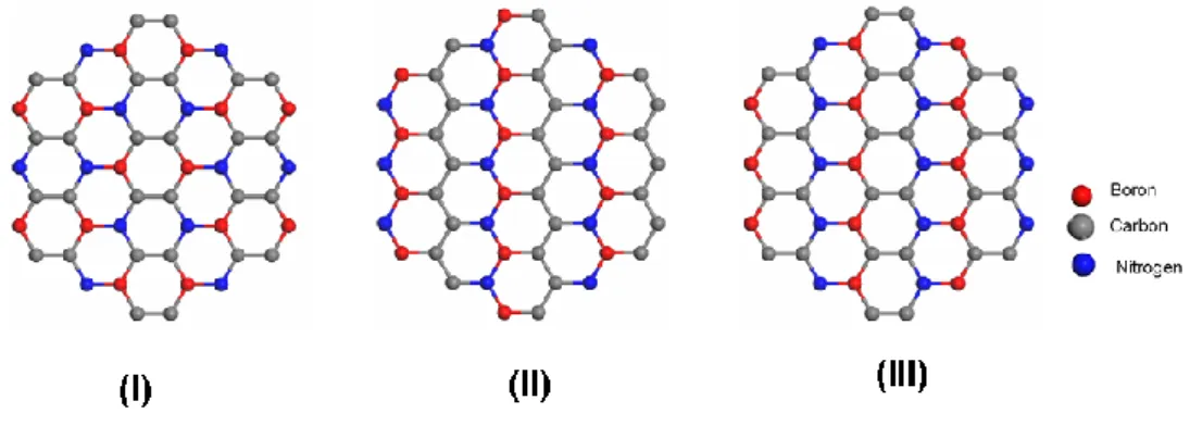
calculations. In Figure 4, the atomic arrangements used by Liu et al.10 are given. It is reported that the total energy of B-C-N layers decreased with the increase in the number of C-C and B-N bonds. Moreover, the calculated electrical properties were shown to be drastically influenced by the change in the atomic arrangement of atoms in the layers. These findings suggest that if the atomic arrangement could be tuned the electrical properties can be controlled without changing the atomic composition. In other words, these materials have variable band structures and they can be used as versatile semiconductors in a range of applications10.
6
Figure 4: Layered h-BC2N structures that are considered by Liu et al.10.
The Nobel prize for physics in 2010 was given to Andre Geim and Konstantin Novoselov for their study on the single-layered carbon sheets, also known as. graphene11. Hybridized graphene and monolayered h-BN (also known as White Graphene) is also a very active topic in the recent literature12. There have been theoretical works on the electronic properties of such mono-layered hybrid structures13, besides various investigation on their synthesis14 and characterization, i.e. atomic resolution imaging of 2-D structures15.
Nanotubes were also studied intensely during the last two decades, as well. There is a large literature about carbon nanotubes and BN nanotubes. The structural similarities between layered carbon and layered BN make it possible to synthesize BCN nanotubes which were first reported by Weng-Sieh et al.16 through arc discharge method. The increase in the importance of BCN related works could be observed better when the numbers of publications that are related with BCN compounds, throughout the years are compiled. The plot in Figure 5 shows total number of articles where “boron, carbon, nitrogen”, “boron carbonitride” and “BCN” were used as keywords versus the publication years for the corresponding work. The data presented here was obtained from Web of Science17. In 1989 two very important articles were published; one of them was about the band gap variation in monolayer h-BC2N related with intralayer
7
atomic arrangement10. Second one is related to the effect of bond distance and ionicity on bulk modulus of tetrahedrally coordinated solids10. The significant effect of those can be easily observed as a break point in the plot shown in Figure 5. Between 1990 and 2000, there has been a steady increase in the number of papers on BCN, mainly fueled by the work on developing a hard, stress free c-BN or β-C3N4 coatings with reproducible performance.
Nonetheless, partial motivation from the 1991 paper by Sumio Iijima on carbon nanotubes should not be counted out18. Hence, in 1995 the first paper on BCN nanotubes was published, as well16. While, a stagnation period followed this region of high activity starting from year 2000 on, nevertheless first synthesis of a hard, crystalline BCN compound, c-BC2N was announced in 20019.
1980 1985 1990 1995 2000 2005 2010 2015 N umb er of Pu bl ica tio ns Year c-BN and β-C3N4 motivated Graphene motivated
Region I Region II Region III
Figure 5: Number of BCN related publications vs. publication year. Three main periods are observed; region I motivated by c-BN and β-C3N4, region 2 stagnation period, and region III the onset of graphene and other 2-D structures era. (Data obtained from Web of Science)
8
In the third period starting with 2007, landmark papers regarding graphene were published which caused a renewed interest on BCN structures but this time the focus was on the mono-layered or 2-D structures and on optoelectronic properties thereof11.
Until now, only the most recent advances and studies during the last two decades on B-C-N ternary were mentioned in this section. However, the history on B-C-N solids dates back to late 60’s. During the space race era, the refractory materials for space vehicles become important for re-entry stage. Lightweight and high temperature resistant materials received significant attraction, thus BCN ceramics were studied for that purpose. The first report on BCN system was published at 1969 by Gingerich K.A.19. In that study, Gingerich attempted to measure the heat of atomization of BCN molecules using mass spectrometry. The main purpose of the study was to investigate the stability of BCN at high temperatures. Kosolapova et al. studied synthesis bulk boron carbonitride with solid state reactions, in 1971, the motivation of this work was develop new high-temperature electrical insulators20. First thin film synthesis of B-C-N materials was reported by Badzian et al.21. In this work, BCN films were deposited by chemical vapor deposition technique and their hardness and high temperature stability was the focus.
There is a large body of work about the deposition of BCN films. Upon the compilation of various deposition techniques used in the literature, one can easily group these methods under four main classes: chemical vapor deposition (CVD), ion beam assisted deposition (IBAD), pulsed laser deposition (PLD) and magnetron sputter deposition techniques (MS). As an example for the CVD technique, a work published by Polo et al. could be mentioned22. In this study, BCN thin films were synthesized by radio frequency plasma assistance chemical vapor deposition where B2H6-N2-CH4 gas mixture was used as a
9
partial pressure of the gases used during deposition. For the case of IBAD, the work reported by Gago et al. could be given as an example23. In this study, BCN films were deposited by co-evaporation of boron carbide and graphite using electron beam evaporation, while the growing film on the substrate was bombarded with nitrogen ions of energy between 200 eV and 2 keV from an ion gun. PLD was used by Wada et al.24. In this study, a stochiometric hot-pressed BC2N target was ablated with a Nd:YAG laser. As an example for the MS
deposited BCN films, the work published by Essafti et al., could be mentioned25. In this work, BCN films were deposited from a boron carbide target material with the radio frequency generated plasma in argon and nitrogen flow. The nitrogen gas flow was adjusted to keep N2 amount in the gas
environment at 50 %. No bias voltage was applied to the substrate during film growth.
As indicated earlier, properties of the BCN thin films were directly related with the atomic structure and chemical environment of the atoms in the thin film. Although, there were numerous publications about the chemical make-up of the atoms in the BCN thin films, there is not a consensus on the bonding chemistry between boron, carbon and nitrogen in the films. Some studies on these films suggest that boron, carbon and nitrogen are hybridized; that is bonding exists between all three of the components without preference in the films. While, there is another school of researchers claiming otherwise, suggesting that phase segregation causes a phase mixture of BN and C-rich phases to be formed in these films. Interestingly, both sides depend heavily on x-ray photoelectron spectroscopy and infrared spectroscopy while supporting their claims. Moreover, in many cases the data reported as evidence are almost identical for both opposing groups, yet only with a strong dissent on interpretation of data at hand.
10
Hence, the objective of this thesis is to provide an accurate understanding of the local chemistry of BCN films using high precision characterization techniques, and ways to control the bonding chemistry in order achieve enough insight to tune properties of BCN solids. In this thesis, BCN films were deposited using reactive magnetron sputter deposition technique using various process parameters, such as changing substrate bias and flow rate of synthesis gas. The resulting films were investigated using transmission electron microscopy (TEM) and electron energy loss spectroscopy (EELS) for the confirmation of the film chemistry. Detailed information about the composition of the films and the local coordination of boron, carbon and nitrogen was collected using ex situ X-ray photoelectron spectroscopy (XPS). Also, infrared spectroscopy was employed to collect similar information about the bonding chemistry. Further analyses on the films were done using Raman Spectroscopy as well. All of the data from the aforementioned analytical tests was used to explain the change in the composition and local chemistry in the deposited films depending on process parameters used. Several hypotheses were built through the elaboration of the data at hand.
In this thesis, the literature review is given in chapter 1.1. In the chapter 2, information about synthesis and characterization techniques and equipments used thereof are mentioned, the experimental procedure is also part of this chapter. In chapter 3, results obtained from the experiments and the related discussions are mentioned. The summary and the discussion relating to the data are given in the chapter 4. In the Appendix, brief information about the thin film technology is given and the final part is about the references.
11
1.1 Literature Review: BCN Thin Film
Synthesis
In this part of the chapter, a general review on the BCN thin films synthesis is provided. The literature on BCN thin films are grouped with respect to deposition techniques used for synthesis; CVD, IBAD, PLD and sputter deposition. Amongst the various techniques for thin films synthesis of BCN, major emphasis is kept on sputter deposition as in this study, the same technique is employed for the synthesis of BCN films, as well. There are numerous studies on BCN thin films, however in these sections only ones with significant scientific impact and relevance to the current studies are covered.
In the studies about BCN thin films, while most reports were concerned with the synthesis, characterization, and understanding of the physical properties, industrial applications of BCN thin films were also considered. One of the most important points about industrial application of thin films in general is to formulate a cost effective and reliable synthesis technique. In the following sections, the techniques utilized are not only considered from a scientific perspective, also analyzed is the applicability of the process in question to high volume manufacturing.
1.1.1. Chemical Vapor Deposition (CVD)
In this technique, the reactant gases are sent through a reaction chamber. The main purpose for this is to induce a reaction between the reactant gases, which will result in the formation of solid-products on a heated substrate. A sample reaction path is shown below:
12
A(g)+B(g)At specific temperature C(s)+D(g) (2)
The reaction is expected to take place only above a certain temperature and only on the substrate. Often, the substrate temperatures used in CVD reaches several hundreds of degrees in Celsius. In some cases, r.f. or microwave excited or ignited plasma is used to drive the reaction at lower substrate temperatures. This also has the added benefit of increasing the deposition rate of the desired thin film. In Figure 6, a schematic representation of plasma enhanced-CVD (PECVD) or plasma assisted-CVD (PACVD) technique is shown.
Figure 6: Schematic representation of PECVD.
As mentioned earlier, the first work about the synthesis of BCN thin films were published in 197221. Badzian et al.21 synthesized BCN films using a hot-wall CVD technique. There are many other studies on BCN thin films synthesized using CVD in the literature26-29. In particular, Sugino and his colleagues investigated properties of BCN thin films that were deposited by PACVD 30-54, field emission properties50, optical and electrical conductivity37. In these studies, a mixture of B2H6, CH4, and N2 were used as precursor gas during
13
PACVD process. Through IR and XPS analysis, it was found that these films were found to be a mixture of h–BN and graphite, thus phase segregation was observed. In addition to Sugino and co-workers, Mannan and co-workers also conducted a series of studies on the BCN thin films synthesis using CVD techniques. In these works, the BCN films were synthesized with a microwave or radio frequency plasma assistance. N2 or CH4 + H2 mixture was used as
carrier gas and a single source molecular precursor (tris(dimethylamino)-borane) was used. The substrate temperatures were between 650-750°C. In these studies, effects of applied power and types of plasma on the atomic arrangement of the films with different compositions were examined. Again, XPS and IR were used for the characterization of the chemistry and atomic structure of the films. Mannan and co-workers concluded that their BCN films were hexagonal with c-axis parallel to the substrate surface (turbostratic-BCN) while further asserting that there was full hybridization between atoms in the same layer55-60.
Although, this technique has been used widely for the deposition of BCN thin films, there are no reports on successful synthesis of metastable phases, e.g. c-BC2N or c-BN. Furthermore, as the substrate has to be heated during this
process, substrate choices are limited with the high temperature durability of the relevant materials. In addition to these, during CVD as the chamber pressures are kept relatively high, the reaction byproducts are inevitable. Hence, the deposited BCN films were sometimes called B-C-N-H materials due to significant amount of hydrogen incorporation to the growing film. Furthermore, the reactants used for CVD during BCN synthesis are generally highly toxic such as B2H6, dangerous for humans and the environment. These render CVD
14
1.1.2. Ion Beam Assisted Deposition (IBAD)
In ion-beam involved techniques, basic components of the films are vaporized using electron beam evaporators. However, the evaporated atoms leave the bulk with very low kinetic energy and cannot be accelerated toward the substrate because of their neutral character. Energetic ions that are used for the structural modification of films are generated and accelerated in ion-guns.
The working principle of the electron beam evaporators is described with a schematic representation of an electron beam evaporator in Figure 7. An electron beam is generated by heating up a tungsten wire, the heated wire starts emitting electrons over a specific temperature range. Emitted electrons are then directed to the material that is to be evaporated. Because of the applied electric field, the electrons gain kinetic energy, as well. When the electron beam hits the target material, this kinetic energy will be converted into heat and the target material will eventually start evaporating.
On the other hand, in the ion gun the desired gas is ionized and the ions are then accelerated towards to the substrate. The ions that are impingent to the substrate surface help to manipulate the structure of the deposited film. The detailed information about effect of ion bombardment on deposited films is mentioned in the Appendix. If the ionized gas is a reactive gas, the vaporized material and the ions are co-deposited on the substrate generally forming a compound through a chemical reaction. If a novel gas used as ion source, it will mostly affect the physical processes taking place during the deposition process of the thin film. In Figure 8, a schematic representation of IBAD technique is shown.
15 e- e -e -e -e-e -e -e
-+
-
-Target
Figure 7: Schematic representation of an electron beam evaporator.
Figure 8: Schematic representation of IBAD.
There were many publications about the IBAD synthesized BCN thin films from many groups. Jimenez and colleagues61-68, studied synthesis of BCN films primarily with IBAD technique. The boron and the carbon source of the atoms in the BCN films synthesized in these works were electron beam evaporated graphite and B4C and source of the nitrogen atoms was the ion gun. In these
16
The substrates were kept electrically grounded and were not heated in these experiments. The purposes of these works were to understand the chemistry of the atoms in BCN films with different deposition parameters. The compositions of the films were changed by changing the evaporation rate of the materials or changing the composition of the ionized gas. The effect of accelerating voltage of the ionized gas and the effect of ion flux on the chemical structure were also investigated. The chemical structure in the films was explored using IR, XPS and X-ray absorption near edge spectroscopy (XANES). In addition to chemical analysis, some of the mechanical test were also applied; hardness, coefficient of friction etc. The conclusion of these works about the chemistry of the BCN films, was that the BCN films were phase-segregated as h-BN/CNx and in
layered sp2 hybridized structure. In addition to Jimenez and co-workers, Zhou and colleagues also studied on the IBAD synthesized BCN thin films. BCN coatings were deposited on Si wafers and Si3N4 disks by evaporating B4C
target, with simultaneous N2 ion bombardment69-71. The substrates were
electrically grounded and not heated during the depositions. The effect of ion energy and the ion flux on the roughness of the film, the mechanical properties like hardness and tribological properties like wear resistance were tested. The chemical composition and bonding were analyzed by using only XPS. The conclusions of the Zhou and co-workers about the chemistry of the atoms in IBAD synthesized BCN films were that the atoms in the films were hybridized but no conclusion about the atomic structure of the films was given. In addition to these groups, some other groups worked on IBAD synthesized BCN films and published these works72-74.
Although, the major deposition parameters were independently controllable for this technique, IBAD is not a widely adapted technique in the industry because of several serious disadvantages. The main shortcomings of the IBAD systems are as follows : a- the coated area is not as wide as the other methods, b- the need for high vacuum during process, < 10-6 mbar, c- for evaporation of
17
refractory materials significant amount of energy is consumed thereby rendering IBAD a very expensive technology.
1.1.3 Pulsed Laser Deposition (PLD)
In this technique high power, high frequency lasers are used to vaporize target material, when the focused laser interacts with the target material, it heats up a small area, thus the material vaporized from surface of target material. In some cases, reactive gases are inserted in to the reaction chamber for co-deposition of the materials. If plasma assistance is used during PLD process, it is called plasma assisted PLD (PAPLD). In Figure 9, the schematic representation of PAPLD system was represented.
For example, Castillo et al. synthesized BCN film from B4C target. Ablation
was performed by KrF excimer laser (λ=248 nm). The chamber was full with N2
gas and the pressure of the chamber was kept at 60 mbar. These films were analyzed in situ by XPS and reflection electron energy loss spectroscopy (REELS). The mean free paths of the electrons in the deposited BCN films were investigated for electronic applications. However, there was not any information about chemical environment of the atoms in the films75. In addition to this work, also a group of scientists from Institute of Atomic Physics, Bucharest, Romania, had a series of publications about PLD synthesized BCN thin films at late 1990s`. In these studies, BCN thin films were synthesized from hot pressed h-BN and graphite. The reaction chamber was fed with reactive gas, N2. Materials
were ablated from target materials with XeCl excimer laser λ=308 nm. The atomic compositions of the films were changed by changing the h-BN/graphite ratio of the target materials and pressure in the chamber (1-100 Pa). The characterization of the films was done with secondary ion mass spectroscopy (SIMS), IR, XPS, scanning electron microscopy (SEM), transmission electron
18
microscopy (TEM), atomic force microscopy and micro hardness. The results indicate that crystals of c-BCN, h-BCN and h-BN are formed76, 77. The main disadvantage of this technique is that the deposition rates of the films were low and PLD is an expensive technique. Due to laser involvement, experienced personnel are required.
Figure 9: Schematic representation of PAPLD.
1.1.4. Magnetron Sputtering (MS)
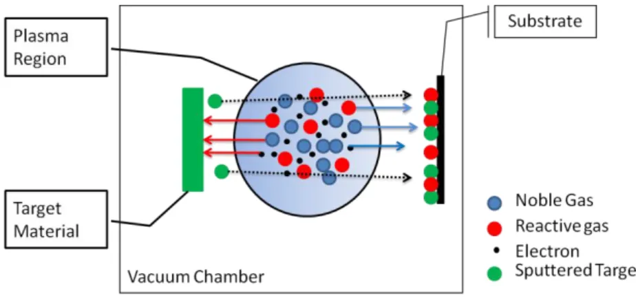
During sputter deposition, target materials are vaporized with ion sputtering. Ions are created in the plasma environment and these created ions are directed to a target material by using electric field. Because of the electric field, these ions gain significant kinetic energy. When the energized ions hit the surface, their effects on the target material are different then electrons. In addition to kinetic energy-heat conversion, a successful momentum transfer occurs because of the similarity in the mass of the ion and atoms in the target. This process will create removed atoms from the surface of the target materials. If the plasma contains reactive gas, the deposited film consists of not only target material but also the atoms of the reactive gas. These types of depositions are called reactive
19
sputter deposition. Detailed information about sputtering and deposition are given in the Appendix. In Figure 10, a schematic representation of reactive sputter deposition is given.
Figure 10: Schematic representation of reactive sputter deposition technique.
Early sputter deposition synthesis works on BCN were published at 1990`s. Motivation for these studies were c-BN coatings. There had been number of studies about sputter deposited c-BN coatings until 1990’s78-87. The problem in the c-BN coatings was the residual stress in the films88. This compressive stress was the reason of the delamination of the BN films. The sputter deposited c-BN films were r.f. sputtered from h-c-BN or boron targets89-93. R.f. plasma has to be used because of the nonconductive properties of h-BN and boron targets.
During this period where c-BN was the most sought after material as a thin film, Luthje et al. were the first to publish on sputter deposited BCN thin films94. Again, the motivation of the synthesis was deposition of low stressed c-BN thin films; actually “BCN” was not used for naming such films. These BCN films were deposited from a B4C target with r.f. plasma. The study claimed that the
cubic phase was achieved when the substrate temperature was 300°C and the applied r.f. generated d.c. bias was between 450 V and 550 V range. The evidences for cubic phase formation were obtained from infrared spectroscopy
20
and transmission electron diffraction pattern of the samples. The residual stress of the film was found to be decreasing with inclusion of the carbon in to the system. The work contains data from series in where only one parameter was changed in each set. In these series, the effect of; (i) gas content in the chamber, (ii) applied substrate bias, (iii) substrate temperature, (iv) oxygen content in the film on the c-BN/h-BN structure in the film were investigated.
The studies about deposition of BCN thin films with sputter technique can be investigated easily by classifying them into three separate groups with respect to the major experimental parameters controlling the structure of the films and the chemical environment of the atoms in BCN films; (i) ion flux and energy, (ii) target composition, (iii) substrate bias and temperature during process. (Further information about thin film deposition phenomena that covers the effect of the above-mentioned process parameters on the final film properties are mentioned in the Appendix)
A) Ion flux and energy:
The above mentioned work94 marks the beginning of studies dealing with the sputter deposition of BCN thin films. In following years, the main emphasis was on the understanding of the effects of process parameters promoting c-BN growth. Especially, the crucial role of energetic ion bombardment during the cubic phase formation was investigated80, 82, 95-97. After Luthje et al.94, there were a number of published studies which investigated the role of ion bombardment on the growth mechanisms of cubic phase of the BN thin films88,
98-101
. Although, in these studies, the deposited films contained significant amount of carbon, thus the films synthesized could be termed as BCN, the authors were only focused on the c-BN phase growth and the experimental parameters, which affect stabilization of the cubic phase. The main reason for
21
the carbon inclusion was the ease of using B4C targets instead of the highly
dielectric and low-yielding BN targets.
In order to investigate energetic ion bombardment effects, the ion density over the substrate was controlled and increased by the help of an external magnetic field perpendicular to the substrate surface. This can be attained by the use of a solenoid placed around the substrate101. The resulting external magnetic field is then used in order to change the electron motion from linear to an helical path. Therefore, the path length of the electrons would be increased so that the larger probability of the collisions will induce an increased ion density above the surface of the substrate. Thus, the ion flux reaching the substrate could be improved significantly. Hence, together with the applied bias on the substrate, this external magnetic field will affect the number of ions impinging on the growing film above the substrate.
The films synthesized using an externally applied magnetic field above the substrate were characterized for confirming the c-BN formation and its relative amount with respect to the h-BN phase using IR, XRD, TEM and other related techniques88, 98-101. The phase separation between BN and retained C was not directly a concern for the authors but nevertheless the resulting films were defined as “c-BN:C”. While, their analyses suggested that the boron and nitrogen in the deposited films were sp3 hybridization, no conclusions were provided regarding the chemistry of the films including the state of carbon. When the microstructure of the films were investigated using TEM100, the HRTEM images indicated that the structure of the c-BN:C films were very similar to those observed for c-BN. In the c-BN:C films, first, an amorphous thin layer is observed over the substrate which is followed by a turbostratic-BN (t-BN) structure. Finally, a cubic phase was observed at the top layer over the turbostratic phase. In these studies, it was shown that to attain a cubic phase “momentum flux” of the impinging ions should be above a certain limit without
22
increasing the average ion energy. In other words, the ion flux impinging on the substrate surface must be increased without increasing the applied bias. If the ion energy is increased in order to increase the “momentum flux”, re-sputtering mechanisms could become dominant rendering very thin films.
B) Target composition
The studies in the literature about sputter deposited BCN thin films can be classified into two groups with regards to targets used as the source for boron, nitrogen and carbon; single-phase targets sputtering and multi-phase target co-sputtering.
B.1. Reactive single source sputtering
In these studies, BCN thin films were reactive sputter deposited from a single target material. These studies can be separated into three group with respect to used target materials:
(a) B4C targets
Several studies reported about the reactive sputter deposition of the BCN thin films from a B4C target25, 88, 94, 98, 100-112. The source for the boron and carbon
atoms was B4C. As for the nitrogen source for the synthesis of BCN films, N2
gas with varying flow rates was used. In these studies, Ar was used as the inert gas. The results from these studies can be summarized as follows:
-At approximately 10 % and over N2 flow, the films saturated with nitrogen and
23
-Boron to carbon ratio indicated some fluctuation. A decrease in the carbon content of the films was observed increasing the N2 flow. This was explained by
the formation of volatile carbon-nitrogen compounds, especially (CN)2.
Although, nearly all of the studies under this category used the same characterization techniques, e.g. IR, XPS and XRD, there was not a consensus about the chemical environment of the atoms. Some of the studies claimed that atoms in the deposited films were showing no preferences for bonding, so the atoms in the films can be bonded to any of the other atoms. This type of films are called atomically hybridized in the literature and in the context of this thesis104, 105, 109, whereas others claimed that the films were the mixture of two phases; h-BN and graphite25, 98, 102, 103.
(b) BN target sputtering
In another group of studies, sputter targets made of h-BN were utilized as the source for boron and nitrogen atoms. As for the source of carbon, carbonaceous gases such as CH4,113, 114 and C2H299 were used. In these studies, the main
attempt was to control the carbon content independently of other parameters. Hence, the carbon content in the films was adjusted by the proportion of the carbon containing reactive molecular gas in the gas flow with respect to the inert gases. These studies concluded that; the boron to nitrogen ratio was larger than unity, causing a boron rich or nitrogen deficient system. The main reason for this observation was the recombination of N atoms sputtered from BN target as N2 molecules. Moreover, the synthesized BCN films stoichiometry was in the
carbon rich region in the ternary phase diagram of BCN. Still, the researchers, leaving the topic a controversy, did not reach a consensus in the chemical environment of the atoms. Some of the studies claimed that there was phase segregation such as BN/carbon99, others claim that the atoms in the films were atomic level hybrids composed of B, C and N atoms.113, 114
24 (c) Boron target sputtering
In order to induce further independence to process parameters controlling the BCN film composition, some studies followed the route of using targets made out of elemental boron115. The nitrogen and argon gas flows were kept constant in the experiment series and the CH4 content in the flow was increased
stepwise. IR, Raman and XPS techniques were used for the characterization. The chemical compositions of the BCN films were found to vary between BN to BC2N. Chen et al.115 claimed that the BCN films were composed of a hybrid
B-C-N structure.
B.2. Multi-phase target co-sputtering
In this synthesis route, thin films were deposited multiple targets or a single target which is composed of multiple compounds (composite target) such as graphite/BN with a set ratio. Generally, BN was used as the source for boron and nitrogen and a carbon or graphite target was used for carbon. The atomic composition of the films was controlled by controlling the target powers for two separate target cases, and in the composite target case by controlling the relative ratios of the compounds. In order to eliminate nitrogen loss -due to of N2 and/or
(CN)2 formation- N2 gas was added to the flowing gas116-121. The films were
characterized by using IR, XPS, Raman, TEM, transmission electron diffraction and reflection electron energy loss spectroscopy (REELS) techniques. Again, there was not a consensus in the chemical environment of the atoms; some of the studies claim that there were phase segregation occurred in the thin films and opponents claimed that films were consisting of atomically hybridized boron, carbon and nitrogen atoms.
25
In addition to hot pressed composite BN/C targets, hot pressed elemental boron and carbon targets were also used106-108. In these studies, several targets with varying compositions were used (B, 4B:C, B:C, B:4C, C). Source of the nitrogen atoms in the BCN films was N2 in the flowing gas. Linss and
co-workers published these papers, The film structure in these published studies concluded phase segregation like h-BN/CNx .
C) Substrate biasing and substrate heating
In order to control the flux and energy of the impinged ions on the substrate of the film the applied voltage on the substrate was used. The significance of the ion bombardment and substrate temperature on the film structure is covered in the Appendix. Briefly, extra energy imparted to the growing films due to energetic ions or by the heat supplied through heating of the substrate. Both of these could initiate or trigger various chemical or physical processes on the surface such as diffusion or chemical reactions. Hence, the effect of heating103,
109, 117, 120-122
and ion bombarding106, 116, 119, 123-125 the substrate were investigated widely. On the other hand, even though the studies used same characterization techniques, the conclusions of the studies about effect of bias and temperature of substrate on the chemistry of the atoms in the sputter deposited films did not agree.
26
1.2. Literature Review: Characterization
Techniques
In the remaining portion of this chapter, results of the works focused on the characterization of the chemistry and physical properties of BCN thin films are described. The focus is particularly kept on studies where infrared (IR) spectroscopy -related techniques and X-ray photoelectron spectroscopy (XPS) have been heavily used; nevertheless, other techniques are also covered. Brief information about the theory of the techniques and advantages and shortcomings with respect to related research will be mentioned. The depth of coverage provided for individual techniques is proportional to the frequency of usage; thus, more detail will be provided for IR and XPS.
1.2.1 Infrared Spectroscopy (IR)
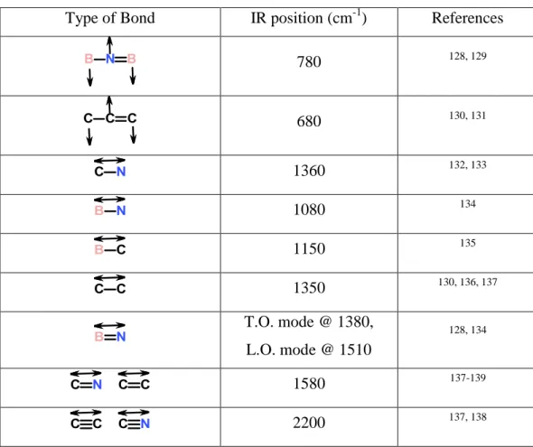
IR is one of the most frequently used techniques for the characterization of bonding in BCN thin films112, 126, 127. As a cheap, easy to implement and quick technique IR can easily provide a wealth of information about the system such as the bonding characteristic, e.g. single or double bond. Table 1 shows a list of possible bonding types and their assigned vibrational frequencies from literature on BCN thin films. Generally, the references used for identifying IR bands and positions are obtained from binary or molecular solids; thus, peak positions are not a universal constant for these chemical bonds. The shifts in vibration frequencies of the bonds are possible and common.
27
Table 1: IR peak positions for relevant bonds for BCN coatings compiled from literature.
Type of Bond IR position (cm-1) References
780 128, 129 680 130, 131 1360 132, 133 1080 134 1150 135 1350 130, 136, 137 T.O. mode @ 1380, L.O. mode @ 1510 128, 134 1580 137-139 2200 137, 138
Although IR technique is a powerful technique to understand the bonding types and types of atoms involved, there are some disadvantages and shortcomings:
(i) This technique is very useful for gases, molecular solids and liquids, but there are some difficulties for using non-molecular solids.
(ii) The absorption coefficient of the bonds depends on the polarity of the bond. The polarities of the possible bonds for BCN films are significantly diverse. Hence, the signal originating from a less polar bond may be overwhelmed by

![Bitkisel ve mikrobiyal kökenli preparatların kültür mantarı [Agaricus bisporus (Lange) Imbach]’nda yaş kabarcık (Mycogone perniciosa) ve kuru kabarcık (Verticillium fungicola) hastalık etmenlerine etkilerinin in vivo ve in vitro koşullarında değerlendiril](data:image/gif;base64,R0lGODlhAQABAIAAAP///wAAACH5BAEAAAAALAAAAAABAAEAAAICRAEAOw==)