Compact size highly directive antennas based on
the SRR metamaterial medium
To cite this article: Irfan Bulu et al 2005 New J. Phys. 7 223
View the article online for updates and enhancements.
Related content
Investigation of magnetic resonances for different split-ring resonator parameters and designs
Koray Aydin, Irfan Bulu, Kaan Guven et al.
-Metamaterials with negative permeability and negative refractive index: experiments andsimulations
Ekmel Ozbay, Kaan Guven and Koray Aydin
-Transmission characteristics of bianisotropic metamaterials based on omega shaped metallic inclusions
Koray Aydin, Zhaofeng Li, M Hudlika et al.
-Recent citations
Selective electroless plating of 3D-printed plastic structures for three-dimensional microwave metamaterials
Atsushi Ishikawa et al
-Beaming and enhanced transmission through a subwavelength aperture via epsilon-near-zero media
Hodjat Hajian et al
-Active plasmon injection scheme for subdiffraction imaging with imperfect negative index flat lens
Anindya Ghoshroy et al
-T h e o p e n – a c c e s s j o u r n a l f o r p h y s i c s
New Journal of Physics
Compact size highly directive antennas based on the
SRR metamaterial medium
Irfan Bulu1, Humeyra Caglayan, Koray Aydin and Ekmel Ozbay Department of Physics and Nanotechnology Research Center,
Bilkent University, 06800, Ankara, Turkey E-mail:[email protected]
New Journal of Physics 7 (2005) 223
Received 31 March 2005 Published 20 October 2005 Online athttp://www.njp.org/
doi:10.1088/1367-2630/7/1/223
Abstract. In this work, we studied the far-field properties of the microwave
radiation from sources embedded inside the split-ring resonator (SRR) metamaterial medium. Our results showed that the emitted power near the resonance frequency of the SRR structure was confined to a narrow angular region in the far field. The measured radiation patterns showed half-power beamwidths around 14◦.The highly directive radiation is obtained with a smaller radiation surface area when compared to the previous results obtained by using photonic crystals. The reduction in the surface area is ten-fold in the case of the SRR metamaterial medium when compared to the photonic crystals. Our results provide means to create compact size highly directive antennas.
Since their introduction by Pendry et al [1], split-ring resonators (SRRs) have attracted great interest among the scientific community [2]–[8]. One of the major reasons for this great interest lies in the fact that the SRR shows strong magnetic activity at high frequencies that is not obtainable with natural materials. Several researchers have demonstrated strong magnetic activity by using SRRs in the gigahertz and terahertz region [2, 9]. In addition to strong magnetic activity, the SRR is a resonant structure whose dimensions are much smaller than the resonance wavelength. The small size of the resonant SRR structure may provide means to modify and control the emission properties of sources with small-sized structures.
1 Author to whom any correspondence should be addressed.
New Journal of Physics 7 (2005) 223 PII: S1367-2630(05)97278-9
+ + + -- -- -+ -+ + r1 r2 g g d w
Figure 1. The SRR structure. The following dimensions are used throughout
our experiments and simulations: g= 0.2 mm, d = 0.2 mm, w = 0.9 mm, r1 =
3.6 mm and r2 = 1.6 mm. Arrows indicate the direction of current flowing around
the structure.
In this paper, we experimentally and theoretically study the angular distribution of microwave radiation from a monopole source embedded inside a SRR metamaterial medium. We will first review two important properties of the SRR structure relevant to the study of radiation sources inside the SRR metamaterial medium. In this sense, we will be concerned with the distribution of the surface current along the SRR structure and the distribution of the electric field within the unit cell of the SRR metamaterial medium. Finally, we will experimentally demonstrate that the radiation emitted from a monopole source embedded inside a SRR metamaterial medium exhibits a highly directive radiation pattern.
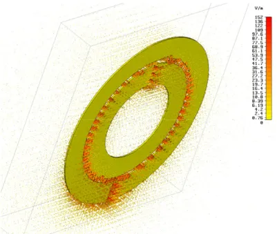
The SRR structure consists of two concentric annuli of conducting material. There is a gap on each ring, and each ring is situated opposite to the gap on the other ring. The schematics of the SRR structure that we used in this study is shown in figure1. When excited by an external source, for example, by a time-varying magnetic field perpendicular to the plane of the SRR, current flows along the rings are induced. The induced current is solenoidal. Hence, the SRR structure can be considered as a resonant magnetic dipole. In fact, the associated magnetic-field pattern from the SRR is dipolar [3]. In addition to the resonant solenoidal current, the SRR structure concentrates the incident electric field within its close vicinity (see video). Figure2shows the simulated electric-field (total field) distribution within the unit cell of the SRR metamaterial medium. We considered a single layer of SRR structure along the propagation direction in the simulations. Periodic boundary conditions were employed on the plane perpendicular to the propagation direction. The incident wave is a planewave with unit amplitude. The electric field shown in figure 2indicates that the incident electric field is localized near the SRR structure. Also, note that the electric-field amplitude attains values as large as second orders of magnitude larger than the incident wave.
The resonant nature of the SRR structure is pronounced as a dip in the transmission spectrum. This dip can be easily observed by measuring the transmission spectrum of a single-SRR structure by two monopole antennas, one transmitting and the other receiving. The monopole antennas that we used in our experiments are obtained by removing the dielectric cladding and the metal shield of a microwave coaxial cable. The left inner core has a length of 7 cm. The monopole
3 InstituteofPhysics
⌽
DEUTSCHE PHYSIKALISCHE GESELLSCHAFTFigure 2. Simulated electric-field distribution within the unit cell of the SRR metamaterial medium. Incident planewave has a unit amplitude. The view angle is tilted for better visualization. (Seevideo.)
length is optimized for operation around 4 GHz. The transmission coefficients of a single-SRR structure placed between two monopole antennas is then measured by an HP-8510C network analyser. HP-8510C is a vector network analyser capable of measuring both the transmission and the phase. The SRR structure is manufactured by standard printed circuit board technology. The substrate is standard FR-4 material and the metal is copper with a thickness of 0.05 mm. The thickness of the board is 1.6 mm and the measured relative permittivity around 4 GHz is 3.85. The measured transmission data and the results of the FDTD simulation are shown in figure3. For comparison, we have also measured the response of the closed SRR structure. In the closed SRR structure we have two complete rings. The transmission data for a single-SRR structure shows a strong dip around 3.65 GHz. Note that this dip is not observed in the transmission spectrum of the closed SRR structure.
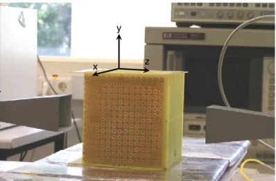
The experimental setup that we used to study the transmission properties of the SRR metamaterial medium is depicted in figure 4. The transmission setup consists of a HP-8510C network analyser and transmitting–receiving horn antennas. The measured metamaterial medium is obtained by arranging SRR structures in a rectangular array. The periodicity along the z- and
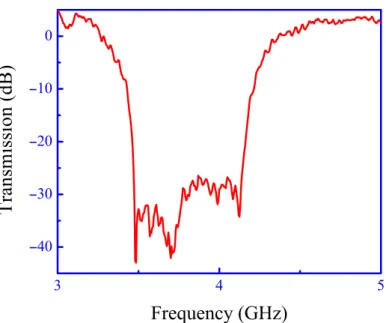
y-axes is equal to 8.8 mm. The periodicity along the x-axis is 6.5 mm. There are 30 layers along the x-axis, 15 layers along the z-axis and 15 layers along the y-axis. The distance between horn antennas and the structure is 15 cm, which is larger than the wavelength at 3 GHz. The measured transmission spectrum of the SRR metamaterial medium is shown in figure5. The orientation of the incident fields and the SRRs is such that the magnetic field is perpendicular to the plane of the SRRs and electric field is orientated along z-axis. The transmission spectrum of the metamaterial SRR medium exhibits a forbidden frequency range between 3.4 and 4.3 GHz.
At this point, we would like to emphasize two important properties of the SRR structure. First of all, at the resonance frequency solenoidal currents flow along the SRR structure. As
Figure 3. Measured transmission spectrum of (A) SRR structure and (B) closed SRR structure. Simulated transmission spectrum of (C) SRR structure and (D) closed SRR structure.
x y
z
Figure 4. Experimental setup used to measure the transmission properties of the SRR metamaterial medium. The setup consists of transmitting-receiving horn antennas and a HP-8510C network analyser.
a result, the SRR structure can be regarded as a resonant magnetic dipole. In addition, the SRR structure localizes the incident electric field within its close vicinity at the resonance frequency. These two properties of the SRR structure makes it interesting for antenna applications. Due to these two properties of the SRR structure, when arranged in a regular pattern, the resulting metamaterial SRR medium may be regarded as an antenna array. An array antenna is made up of more than one radiating element [11].
One usually expects that the field intensity decreases strongly with the distance from the source. This means that when the surface is considered as a collection of individual antennas, the
5 InstituteofPhysics
⌽
DEUTSCHE PHYSIKALISCHE GESELLSCHAFTFigure 5. Transmission spectrum of the electromagnetic waves through the
SRR metamaterial medium. Electric field is orientated along the z-axis and the magnetic field is perpendicular to the plane of the SRR structures.
b) –60 –40 –20 0 20 40 60 0 10 20 X (cm) Y (cm) –60 –40 –20 0 20 40 60 0 10 20 X (cm) Y (cm) a )
Figure 6. (a) Measured electric-field intensity near the surface of the SRR array at 3.8 GHz when the source is located inside the array; (b) measured electric-field intensity near the surface of the SRR array at 4.7 GHz when the source is located inside the array. The scales are the same for both figures.
contribution of each antenna to the emitted radiation decreases with distance from the monopole antenna. In order to check the above statement, we measured the electric-field intensity near the surface of the SRR array when the monopole source was placed inside it. In our measurements we used another monopole antenna as a receiver to measure the electric-field intensity. The measurements are carried out over an area of 150× 20 mm2 with steps of 1 mm. The data for
the resonance frequency is shown in figure 6(a). At the resonance frequency a significant part of the surface contributes to the radiation appreciably. On the other hand, at the off-resonance frequency (4.7 GHz) a small part of the surface contributes to the radiation (figure6(b)).
For the far-field radiation pattern measurements, we replaced the transmitting horn antenna with a monopole antenna and placed this inside the SRR metamaterial medium. We followed the method suggested by Drozd et al [12] in the construction of the monopole antenna. The
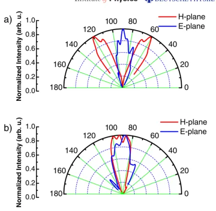
b) 0 20 40 60 80 100 120 140 160 180 0.0 0.2 0.4 0.6 0.8 1.0 3.80 GHz 3.83 GHz 3.86 GHz 3.90 GHz
Normalized Intensity (arb. u.)
0 20 40 60 80 100 120 140 160 180 0.2 0.4 0.6 0.8 1.0 H-plane E-plane
Normalized Intensity (arb. u.)
a)
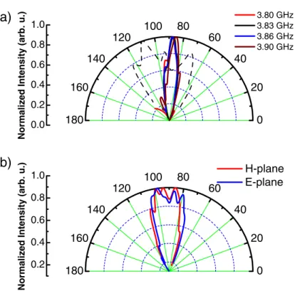
Figure 7. (a) Far-field radiation pattern in the H -plane (———) and E-plane
(- - - -) near the resonance frequency of the SRR structure. (b) Far-field radiation pattern in the H -plane (red curve) and E-plane (blue curve) at an off-resonance frequency. Frequency for this plot is 4.7 GHz.
placement of the monopole antenna inside the SRR metamaterial medium was chosen such that the monopole antenna effectively excites the SRR structures at the surface of the medium. As a result, there are three layers of SRR planes in front of the monopole antenna. The orientation of the monopole antenna was along the z-axis. The monopole antenna was placed at the middle of the SRR array along the x-axis and z-axis. Hence, there are 15 SRR layers to the left and right of the monopole along the x-axis. Along the z-axis, there are seven layers above and below the centre of the monopole antenna. Given the above dimensions, the surface of the SRR metamaterial medium was two wavelength long along the y- and z-axes. The power spectrum of the radiation emitted by the monopole antenna was then measured at a distance of 1.5 m away from the metamaterial SRR medium. The measurements were made by varying the angle in the x–y-plane (H -plane) and y–z-plane (E-plane). Figure7(a) shows the measured angular distribution of power near the resonance frequency of the SRR structure. The half-power beamwidth was approximately 14◦for the frequencies near the resonance frequency in the
H-plane. These results show that the emitted power is confined to a narrow angular region near the resonance frequency. The experimental far-field radiation pattern near the pass-band frequencies is presented in figure7(b). Figure 7(b), on the other hand, shows that the emitted power at the pass-band does not show a highly directional radiation pattern. The half-power beamwidth at 4.7 GHz is 36◦in the H -plane. The measured far-field radiation patterns in the E-plane are also shown in figure 7. Radiation patterns for both the resonance (figure 7(a)) and off-resonance frequencies (figure7(b)) do not exhibit high directionality in the E-plane. We performed similar experiments with the closed-ring resonator (CRR) arrays. The dimension of the individual CRRs
7 InstituteofPhysics
⌽
DEUTSCHE PHYSIKALISCHE GESELLSCHAFT b) 0 20 40 60 80 100 120 140 160 180 0.0 0.2 0.4 0.6 0.8 1.0 H-plane E-planeNormalized Intensity (arb. u.)
0 20 40 60 80 100 120 140 160 180 0.0 0.2 0.4 0.6 0.8 1.0 H-plane E-plane
Normalized Intensity (arb. u.)
a)
Figure 8. (a) Far-field radiation pattern in the H -plane (red curve) and E-plane (blue curve) near the resonance frequency of the SRR structure. Frequency for this plot is 3.8 GHz. (b) Far-field radiation pattern in the H -plane (red curve) and
E-plane (blue curve) at an off-resonance frequency. Frequency for this plot is 4.7 GHz.
and the size of the CRR array were the same as the SRRs and SRR array. The measured far-field radiation patterns when the monopole source was located inside the CRR array is shown in figure 8for the H -plane and E-plane. Figures8(a) and (b) show that the emitted radiation is not confined to a narrow angular region either in H -plane or in E-plane for both the resonance and off-resonance frequencies. These results can be interpreted as follows. At the resonance frequency SRRs act as a magnetic dipole whereas CRRs do not. As a result, SRR array can be considered as a collection of antennas. On the other hand such an interpretation cannot be done for the CRR array.
In a previous work, we showed that photonic crystals may be used to obtain highly directive radiation from sources [13]. Also, Enoch et al [14] reported similar results by using a metallic mesh of thin wires. The results of both of these previous works are related to the anisotropy of the band structure associated with the wave propagation inside photonic crystals. A physical explanation of highly directive radiation from sources embedded inside photonic crystals is provided by Chigrin et al [19] in terms of stationary phase. In addition several other researchers have reported directional radiation sources based on photonic crystals [15]–[18]. On the other hand, the highly directional radiation near the resonance frequency from a source embedded inside an SRR array is due to the resonant behaviour of the individual SRRs. It is worth comparing these values with our previous results obtained by using photonic crystals. For the
Figure 9. Far-field radiation pattern from a rectangular aperture when it is illuminated by a plane wave. The dimensions of the aperture are equal to the dimensions of the SRR array. The surface of the aperture is on the x–y plane. The frequency is 3.86 GHz.
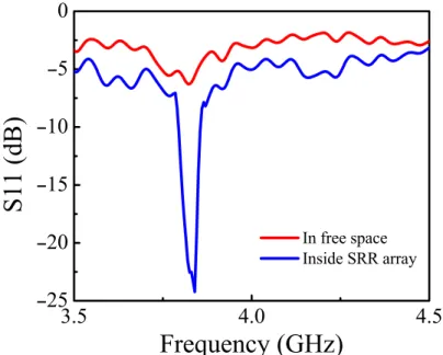
Figure 10. Measured S11 for the monopole source in free space (red curve) and
9 InstituteofPhysics
⌽
DEUTSCHE PHYSIKALISCHE GESELLSCHAFTcase of the photonic crystal, the radiation surface had an area equal to 44λ2, where λ is the
operation frequency. In contrast, the surface area in this work is only 3.8λ2. This means that the
surface area is approximately reduced by a factor of 11 times when compared to the photonic crystals that are composed of regular arrays of dielectrics or wire arrays. We believe that this improvement is important for compact size highly directional radiation sources. We also calculated the far-field radiation from a rectangular aperture of the same dimension of the SRR array for comparison. The results of the calculations in spherical polar coordinates are presented in figure 9. The half-width in the H -plane is 18◦. Note that this value is larger than the one obtained by using the SRR array.
We also checked the coupling efficiency of the monopole antenna by measuring the S11 values. The measured S11 values when the source is placed inside the SRR array and in free space is shown in figure 10. The measured S11 value at the resonance frequency is −5 dB when the source is placed in free space. On the other hand, when the source is located inside the SRR array S11 value reduces down to −24 dB at the resonance frequency. These results clearly indicate that the coupling efficiency is enhanced appreciably when the source is placed inside the SRR array. The coupling efficiency is quite important for practical applications. The enhanced coupling efficiency may be attributed to the high local electric fields near the SRRs.
In conclusion, we showed that near the resonance frequency of the SRR structure the surface of the SRR metamaterial medium can be regarded as a collection of resonant magnetic dipoles. When excited with a monopole source the SRR metamaterial medium exhibited a highly directive radiation pattern. The measured half-power beamwidth is comparable with the results obtained by photonic crystals in the previous works. In addition, the surface area is appreciably reduced compared to the highly directive radiation source based on photonic crystals. Hence, the results presented in this paper provide a new way to obtain compact-sized highly directive antennas. Acknowledgments
This work was supported by EU-DALHM, EU NOE-METAMORPHOSE, EU-NOE-PHOREMOST, TUBITAK, and MSB-KOBRA-002. One of the authors (EO) acknowledges partial support from the Turkish Academy of Sciences.
References
[1] Pendry J B, Holden A J, Robbins D J and Stewart W J 1999 IEEE Trans. Microw. Theory Tech.47 2075
[2] Shelby R A, Smith D R and Schultz S 2001 Science292 79
[3] Smith D R, Padilla W J, Vier D C, Nemat-Nasser S C and Schultz S 2001 Phys. Rev. Lett.84 4184
[4] Parazzoli C G, Greegor R B, Li K, Koltenbah B E C and Tanielian M 2003 Phys. Rev. Lett.90 107401
[5] Li K, McLean S J, Greegor R B, Parazzoli C G and Tanielian M H 2003 Appl. Phys. Lett.82 2535
[6] Marques R, Medina F and Rafii-El-Edrissi R 2002 Phys. Rev. B 65 1440
[7] Katsarakis N, Koschny T, Kafesaki M, Economou E N and Soukoulis C M 2004 Appl. Phys. Lett.84 12
[8] Markos P and Soukoulis C M 2002 Phys. Rev. B 65 033401
[9] Yen T J, Padilla W J, Fang N, Vier D C, Smith D R, Pendry J B, Basov D N and Zhang X 2004 Science
303 1494
[10] Ramakrishna S A 2005 Rep. Prog. Phys.68 449
[11] Balanis C A 1997 Antenna Theory: Analysis and Design (New York: Wiley)
[12] Drozd B, Drozd B and Joines W T 2004 Comparison of coaxial dipole antennas for applications in the near-field and far-field regions Microwave J. (May)
[13] Bulu I, Caglayan H and Ozbay E 2003 Appl. Phys. Lett.83 20
[14] Enoch S, Tayeb G, Sabouroux P, Guerin N and Vincent P 2002 Phys. Rev. Lett.89 213902
[15] Poilasne G, Lenormand J, Pouliguen P, Mahdjoubi K, Terret C and Gelin Ph 1997 Microwave Opt. Technol. Lett.15 384
[16] Poilasne G, Pouliguen P, Mahdjoubi K, Terret C, Gelin Ph and Desclos L 1999 Microwave Opt. Technol. Lett.
22 10
[17] Qiu M and He S 2001 Microwave Opt. Technol. Lett.30 41
[18] Simovski C R and He S 2001 Microwave Opt. Technol. Lett.31 214