^ íV? Vi V -'^ iv.;>' y φ:ί, r · 3 r ^ ' rV >ί. ^ i> í f í f * w·«. ¿ ¿'U-iíbi-rf ^ V./ед·^, .í, '^r
ш Ÿ·/ # * Í ¿ ^ i ' V a α 5 ¿ > v ¿ ,
.f'o.ï*; ..•"i·;·»ίΓ
1
^ ,· '.'i- f'¡ y ’ІЛл4 . i i., t.. £: -i -r^-λ^' SS^.UilEäyüi^'j'Sil' T'Cií ΊΠ Κ ίΙ іОлВіг^НД іШ -'і^хіи 'iÄ ? іВ і^Ж С Я Л Ж £ :;М і.^^^^
^13£:ЛЛ^^'0А;ШС<^ !5 :> :iSilj^3 í;lb'J-S
? ; . ¡tr*. , •’Г > i*,J .:i-' .'■ ;. '■ ·'»■· ., ; · 'il' .' ■· ■. ·'/. ·'■ V; >' ■ ■ я Ϋ· i « » o a ¿ KCii W W . i. » >. ; . ‘^' ¿ · 4 « r / í ? á 7 2 ' ¿ 4 1 ^ S S(338
PLANE-WAVE THEORY OF SINGLE-CRYSTAL
UPCONVERSION OPTICAL PARAMETRIC
OSCILLATORS
A THESIS
SUBMITTED TO THE DEPARTMENT OF ELECTRICAL AND ELECTRONICS ENGINEERING
AND THE INSTITUTE OF ENGINEERING AND SCIENCES OF BILKENT UNIVERSITY
IN PARTIAL FULFILLMENT OF THE REQUIREMENTS FOR THE DEGREE OF
MASTER OF SCIENCE
By
Yamaç DikiiK'lik August 1998
Тк
7S7İ2.
■οψ
■ DS5
I certify that I have read this thesis and that in my opinion it is fully adequate, in scope and in quality, as a thesis for the degree of Master of Science.
A.SSO C. Prof. Dr. Orhcin Aytiir (Supervisor)
I certify that I hcive read this thesis and that in my opinion it is fully adequate, in scope and in qucility, as a thesis for the degree of Master of Science.
L h L i
Assoc. Prof. Dr. Ir,şadi Aksun
I certify that I have read this thesis and that in my opinion it is fully adequate, in sco
25
e and in quality, as a thesis for the degree of Master of Science.Assoc. Prof. Dr. Haldun Özakta.ş
Approved for the Institute of Engineering and Sciences:
Prof. Dr. Mehm^t Baray
Director of Institute of Engineering and Sciences
ABSTRACT
PLANE-WAVE THEORY OF SINGLE-CRYSTAL
UPCONVERSION OPTICAL PARAMETRIC
OSCILLATORS
Yamaç Dikmelik
M .S. in Electrical and Electronics Engineering Supervisor: Assoc. Prof. Dr. Orhan Aytiir
Aiignst 1998
'rhis thesis pi'('s('nts a theoi'etical analysis of single-crystal upconversion op tical parametric oscillators (O P O ’s) where a single nonlinear crystal is used for both the OPO and sum-frequency generation (SPG) or second-harmonic genera tion (SHG). In these devices, the OPO and SFG/SHG processes are both phase matched for the same direction of propagation inside the crystal. Different po larization geometries for which this simultaneous phase matching condition can potentially be satisfied are identified and categorized, for both biréfringent. a.nd quasi-phcise matching methods. This categorization results in four classes of sum- frequency generating O P O ’s (SF-OPO’s) and three classes of self-doubling O PO ’s (SD-OPO’s). Plane-wa.ve coupled mode equations a.re presented for each of these seven classes. Solutions of these coupled mode equations, and calculation of the single-pass saturated signal gain are outlined. The dependence of the photon conversion efficiency on various design parameters are investigated. .Λ pulsed plane-wave model that takes into account the temporal profiles of the fields and the group velocity mismatch between pulses is constructed. This model is in good qualitative agreement with experimental measurements of a class-G SF-OPO.
Keywords: Noidinear frequency conversion, optical parametric oscillatoi-s. parametric devices, sum-frequency generation, second-harmonic generation, (|uasi- pha.se matching
ÖZET
Т Е К K R İST A L L İ Y U K A R I-Ç E V R İM O P T İK P A R A M E T R İK O SİL A T Ö R L E R İN İN D Ü Z L E M -D A L G A T E O R İSİ
Yamaç Dikmelik
Elektrik ve Elektronik Mühendisliği Bölümü Yüksek Lisans Tez Yöneticisi: Doç. Dr. Orhan Aytür
Ağustos 1998
Bu tezde, tek bir doğrusal-olmayaıı kristalin hem parametrik üretim, hem de toplam-frekansı üretimi (SFG) veya ikinci-harmonik üretimi (SHG) için kul- lamldığı tek-kristalli yvdvan-dönüşüm optik parametrik osilatörlerinirı (OPO) ku ramsal analizi sunulmaktadır. Bu cihazlarda, hem OPO hem de SFO/SHG süreçleri kristcil içindeki aynı yayılım yönü için faz e.didir. Bu aynı sırada faz eşli olma koşulunu sağlayabilecek farklı polarizasyon geometrileri, hem çift-kırınımh hem de yaklaşık faz eşleme yöntemleri için belirlenmiş ve sınıflandırılmıştır. Bunun .sonunda, toplam-frekansı üreten O P O ’lar (SF-OPO) için dört, ikinci-harmonik üreten O P O ’lar (SD-OPO) için üç sınıf belirlenmiştir. Bu yedi sınıf için ayrı a}^·! düzlem-dalga bağlı mod denklemleri ve tek-geçişte doygun sinyal kazancı hesabı sunulmuştur. Foton dönüşüm veriminin çeşitli tasarım parametrelerine olan bağlılığı incelenmiştir. Alanların zamansa] profilini ve darbe grup hızı uyum suzluğunu hesaba katan bir darbeli düzlem-dalga modeli oluşturulmuştur. Bu model, deneysel bir (.'-sınıfı SF-OPO’nun ölçümleri ile uyumlu sonuçlar vermiştir.
Anahtar kelimeler. Doğrusal olmayan frekans dönüşümü, optik parametrik osilatörler, parametrik cihazlar, toplam-frekansı üretimi, ikinci-harmonik üretimi, yaklaşık faz eşleme.
A C K N O W L E D G M E N T S
I would like to express iny sincere gi'cititucle to Dr. Orhan Aytrir for his su pervision, guidance, suggestions, and especially encouragement throughout the development of this thesis.
1
would also like to thank the members of niy committee. Dr. Ir.'^adi Aksun and Dr. Haldun Ozakta^, for their valuable comments on the thesis.Special thanks to my friends for all their help and for rnciking life at Bilkent more enjoyable.
Finally, I would like to thank my family for the encouragement and support they hcive provided throughout my life.
Contents
1 Introduction 1
2 Second-Order Nonlinear Interactions 4
2.1
The driven wave equation4
2.2
Coupled mode equatioirs6
2.3 Pha.se mal c lu n g ... 7 2.3.1 Biréfringent phase m a tch in g ... 7
2
.3.2
Quasi-phase matching8
2.4 Optical parametric amplification ... 9 2.5 Optical parametric o s c illa tio n ... 13
2.6
Sum-frequency generation 152.7 Second-liarnionic g e n e ra tio n ... 17
3 Simultaneous Phase Matching of OPO and SFG /SH G 21
3.1 Simultaneous phase matching of OPO and S1*'C
22
3.1.1 Biréfringent pha.se nicitching... 23 3.1.2 Quasi-phase matching ... 25
3.2
Simultaneous phase matching of OPO and SIIC 26 3.2.1 Bircfringent pliase m a tch in g ... 263.2.2 Qua.si-pha.se nurtching 28
4 Single-Pass Solutions 30
4.1 Single-pass solutions of SF-OPO’s ... 30 4.1.1 Class-Λ s o lu tio n s ... 31
4.1.2 ( 3a.ss-B solutions 32
4.1.3 Class-C solutions 32
4.1.4 ( 3a.ss-l) s o lu tio n s ... 34 4.2 Single-pass solutions of Sl)-O P O ’s ... 36
4.2.1 Glas.s-A s o lu tio n s ... 37 4.2.2 C'la.ss-B solutions... 38
4.2.3 Class-C s o lu tio n s ... 38
5 Plane-Wave Theory of Single-Crystal Upconversion OPO’s 39
5.1 SF-OPO’s ... 5.1.1 Class-A SF-OPO’s 41 5.1.2 Class-B SF-OPO’s 43 5.1.3 Class-C SF-OPO’s 46 5.1.4 Class-D SF-OPO’s 48
5.2
SD-OPO’s ... 5.2.1 Class-A SD-OPO’s ... ... 515
.2.2
Cla.ss-B SD-OPO’s 53 5.2.3 Class-C SD-OPO’s 546 A Pulsed Plane-Wave Model 7 Conclusions
56 60
List of Tables
2.1 Potential phase matching types for BPM of second-order nordinear interactions... 3.1 Possible combinations of BPM types for OPO with simultaneous
SFC...
3.2
Possible combinations of BPM types for OPO with simultaneous SHC. . .6.1
Values of the physical parameters used in the pulsed plane-wave model calculations.23
27
0
IList of Figures
2.1 Polarization geometries for BPM
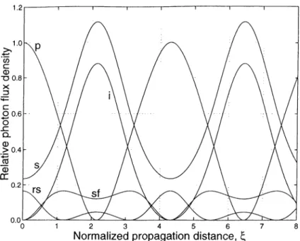
2.2 The evolution of the pump, signal, and idler photon flux densities in an ΟΡΛ cis functions of the normalized propa.gation distance. 13 2.3 The intracavity signal flux density of an OPO is found by the
intersection of the gain saturation curve and the resonator loss line. 14 2.4 Photon com'ersion efficiency of the OPO as a function of the non
linear drive for four different values of R o c ... 16 2.5 Optimum output coupler reflectance for the OPO as a function of
the nonlinecir drive... 16
2.6
The evolution of the lower frequency SFG input, higher frequency SFG input, and sum-frequency i)hoton flux densities as functions of the normalized propagation distance... 18 2.7 The evolution of the fundamental and the second-harmonic photonflux densities in SHG as functions of the normalized propagation distance...
20
3.1 Polarization diagrams for possible combinations of BPM types in SF-OPO’s... 24 3.2 Polarization diagrams for possible combinations of BPM types in
SD-OPO’s... 27 4.1 Single-pass solutions for a class-G SF-OPA for ,'i — 1.5. 33 4.2 Single-])ass solutions for a class-D SF-OPA for /f = 1.5... 35 4.3 Single-pass solutions for a class-y\ SD-OPA for β = 1 .5 ... 37
5.1
Gonversioii efficiency of c la s s -S F - O P O ’s as a function of thenonlinear drive for various values of β. 42
5.2
Gonversion efficiency as a function of the nonliiu'ar drive for various values of L for a chiss-A Sh'-OPO...43
5.3 5.4 5.6 5.7 5.8 5.9 5.10 5.11
Conversion efficiency, pump depletion, and rotated pump depletion as functions of the pump ])ola.rization rotation angle for a class-B SF-OPO...
44
Conversion efficiency as a function of the nonlinear drive for dif ferent values of /4 for a class-B SF'-OPO... 46 Conversion efficiency, pump dephffion, and rotated pump depletion as functions of the pump polarization rotcition angle for a. class-C SF-OPO... 47 Conversion efficiency as a function of the nonlinear drive for dif ferent values of ft for a class-C SF-OPO... 48 Conversion efficiency, pump depletion, and rotated signal depletion as functions of the signal polarization rotation angle for a class-D SF-OPO... 50 Conversion efficiency as a function of the nonlinecu· drive for various
values of ft for a cla,ss-D SF-OPO... 51 Conversion efficiency, pump depletion, and intracavity signal flux
density (normalized to the input pump flux density) as functions of the nonlinear drive for class-A SD-OPO’s... 52 Conversion efficiency, pump depletion, and rotated signal depletion of class-C SD-OPO’s as functions of the signal polarization rotation angle for four different values of /4... 54 Conversion efficiency as a function of the nonlinecu· drive for various values of ft for a class-C SD-OPO... 55 Conversion efficiency as a function of the pump polarization rota tion angle. The solid line represents the model’s predictions cind the filled circles correspond to experimental nuxisurements... 59
Chapter 1
Introduction
Lasers find applications in many fields such as telecommunications, medicine, de fense, printing, entertciinrnent, and basic science. A particular application places various demands on a number of laser properties such as its wavelength, power, beam profile, and bandwidth. One of the most important laser properties is the wavelength of operation.
The operating wavelength of a laser is determined by the energy level differ ences of the material used as the laser gain medium. For most laser materials, these energy level differences are fixed and the operating wavelength of the laser cannot be tuned. Even though tunable lasers that utilize transitions between broad energy bands exist, the wavelength ranges for these lasers are relatively narrow.
It is of great technological importance to convert the output of a laser to diflerent wavelengths in a.n efficient manner. This conversion can be achieved using nonlinear optical materials. In such materials, the polarizcition density has a nonlinear dependence on the electric field. For most nonlinear materials userl in frequency conversion, this nonlinear dependence is quadratic. This second- order nonlinear dependence leads to an energy exchange between optical fields at d i fferent wavelengt h s.
Second-order nonlinear interactions lead to such frequency conversion ap])li- cations as second-harmonic generation (SIICl), sum-frequency generation (SFC), and difference-frequency generation (DFG). With SHC, the output beam ol a laser can be converted to a beam at twice the fre(|uency. SHCl is the most widely used second-order interaction, since this process requires only a single laser. In SFC and DFG, two lasers with different frequencies are used to generate the
sum-frequency or the difference-frequency of the frequencies of tlie two lasers. Another second-order interaction is optical parametric amplification; of the two input beams lor the DFG process, the lower frequency beam is amplified. The gain provided l)y an optical parametric amplifier (OPA) can be enclosed in an optical cavity to construct an optical parametric oscillator (OPO), much like a laser amplifier is enclosed in a cavity to construct a laser. The OPO requires a single laser as its input; this laser is the source of energy for the OPO cind is said to pump the OPO. The initial light energy at the amplified frecjuency is provided by parametric fluorescence, similar to spontaneous emission in lasers. This fact also allows for the tunability of O PO ’s. This tunability is achieved by manipulating the momentum conservation (phase matching) condition by rotating the nonlinear crystal or by changing the crystal’s temperature.
By itself, an OPO can only provide downconversioii to longer wavelengths. Upconversion to shorter wavelengths is achieved with the use of SHG or .SFG in conjunction with an OPO. One approach is to first frequency-double the laser and then use the second-harmonic as the OPO pump [
1
], [2
]. A more widely used technique is to use the OPO output for SHG in a second nonlinear crystal, either outside [3] or inside [4], [.5] the OPO cavity. Intracavity SHG is usually more efficient because of the high intensity of the resonant field. SFG of the OPO output with the pump laser also provides upconversion, and can be imple mented extracavit}^ or intracavity [6
], [7]. These two crystal upconversion O PO ’s have successfully generated tunable light at visible wavelengths, but with limited conversion efficiencies.Single-crystal ui^conversion O P O ’s, where SHG [
8
] or SFG [9] takes place within the OPO crystal itself, have recently been demonstrated. These new devices provide highly efficient schemes for frequency u])conversioii.The modeling of practical O P O ’s is an involved tcisk. The simi)lest (Vpproach is to assume that the fields are uniform monochromatic plane waves. However, in a real OPO, the pump beam usually has a Gaussian transverse profile. If the pump laser is pulsed, the temporal profiles of the pulses also have to be taken into account. For O P O ’s pumped with ultrafast lasers, the ultrashort pulses get separated in the interaction, due to their differing grou|J velocities. 'Phis effect is called group velocity mismatch (GVM ). .Such ultrashort pulses aix' also broadened in the nonlinear crystal, due to group velocity dispersion (GVD). Furthermore, the intense resonant pulse in the OPO cavity is modified by self-phase modulation.
a third-order nonlinear effect, in the nonlinear crystal. To account for all these effects accurately, coupled nonlinear partial differential equations that govern the propagation and nonlinear interaction of fields have to be solved. Moreover, these solutions should be iterated for several round trips in the OPO cavity, to find the steady-state temporal and transverse profiles of the resonated field.
The plane-wave theory of O P O ’s was investigcited in the early sta.ges of OPO development [10]. The effects of Gaussian profiles were first investigated by as suming plane-wave solutions at each point in the transverse plane [
11
]. The effects of transverse and temporal profiles for pulsed O PO ’s operating in the nanosecond regime have recently been investigated with an accurate numerical model [12
]. The effects of GVM and GVD on ultrafast OPO performance were first modeled by assuming plane-wave transverse profiles [13], [14], and then by taking into account the more realistic Gaussian profiles [b5], [16]. The plane-wave theory for two-crystcd upconversion O P O ’s has also been studied [10], [17], [18]. Even though the plane-wave analyses cannot model an experiment ciccurately, they bring out the fundamental physics behind these devices.In this thesis, the plane-wave theory of single-crystal upconversion O PO ’s is presented. The theoretical background on second-order nonlinear interactions is provided in Chapter
2
. Possible phase matching geometries are identified and classified, and the associated sets of differential equations are presented in Chap ter 3. Next, solutions of these sets of equations are discussed in Chapter 4. In Chapter ·5, the dependence of the conversion efficiency and other OPO perfor mance measures on physical parameters are investigated. A pulsed plane-wav(' model that takes into account temporal profiles and CVM is constructed in Cha.|)- ter6
. Finally, conclusions and future directions are presented in Chapter 7.Chapter 2
Second-Order Nonlinear
Interactions
111
this chapter, we first present the wave equation for a nonlinear medium, where the polarization density is a nonlinear function of the electric field. Three optical fields interact through a second-order nonlinearity, and this interaction is gov erned by the coupled mode equations which are presented next. We then discuss phase matching, a condition that has to be satisfied for efficient frequency con version. We finally introduce optical parametric amplification, optical parametric oscillation, SFC!, and SHG.2.1
The driven wave equation
The interaction of optical fields in a second-order nonlinear medium is governed Iry the driven wave equation, do arrive' at this eqimtion, one can start with Maxwell’s equations in a. medium with no free charges and currents
and the constitutive' relations
V D = 0 (2.1) V B = 0 (2.2) V X E OH -(2.3) V X H OD di (2.4) ions D = cqE + P (To) B = /¿oH. (2.6)
The consititutive relation for B [Equation (2.6)] assumes that the materici.1 is nonmagnetic.
In a nonlinear medium, tlie polarization density P 1ms a nonlinear dependence on the local electric field E [19]. When the fields a.re a discrete sum of monochro matic plane waves at different frequencies, P can he expressed in the powers of E a.s
P = fo[x‘ ' ’ - E - h E - x ('^ )-E -f E - ( E · v<">-E) + ···] (2.7) = P ‘ ^> + P ‘^> + P(·^) + · · · (
2
.8
) where is the linear electric susceptibility tensor, is the second-order nonlinear susceptibility tensor, and so on. In materials that do not have a center of symmetry, is nonzero and higher order nonlinearities can usually be neglected. The focus of l.his tho.'sis is on second-order nonlinear interactions in such materials.The driven wave eciuation is obtained bj^ taking the curl of Equation (2.3), and substituting Equation (2.4). For uniform plane waves, the driven wave equation can be simplified by using the vector identity V x V x E = V ( V - E ) — V^E, since V · E = 0 for a phme wave [19]. The driven wave equation then becomes
V^E = ¡J.Qd'^T>
W (2.9)
It is convenient to split the linear and second-order noidinear optical properties of the medium so that,
D = D'^ + P'^) (
2
.10
)wlu're
D^ = eo E -fP < ‘ * (
2
.1 1
) is the linear part of D. With this separation, the driven wave equation takes the formV ' E - / / . o - ^ = /io— vr— . - Q
2
f ■ (2
.12
) d'o put the driven wave equation in a form where we can interpret the (dfect of tlie second-order nonlinear polarization density, we consider the simple case of an isotropic medium, for which is a scalar quantity rather than a tensor. 'Fhen, the driven wave (Xjuation can be expressed asV '^ E
-¿ ) 2 p ( 2 )
= Mo- (2.13)
^2
i)2
[ [)2
lwhere n = \Ji + \3b is the refractive index of tlu' medium. I'lie second-order nonlinear part of the polarization density acts as a source term in tlu' driven wave equation and leads to the generation of new o])tical fre(|uencies [19].
2.2
Coupled mode equations
In a second-order nonlinear medium, the nonlinear part of the polarization den sity is a cpiadratic function of the electric field, and the nonlinear interaction is between three waves that satisfy the frequency relation u-q = u>y -|-u
;2
[19], [20]. For uniibrm plane waves propa.gating collinearly in the .^-direction, the scalar form of Blquation (2.13) is adequate. When these plane waves are also monochromatic, one can define complex amplitudes A by= Re[zl„,e^'(‘^"‘‘ “ ^·”·"*] ?ri = 1,2,3 (2.14) where km = are the wavenumlxu's. The refractive indices ??.„( are allowed to be different for each wave since real materials are dispersive and the natural birefringence of anisotropic crystals is used for phase matching (see Section 2.3). We also represent the nonlinear polarization at each frequency as
Pm [z P ) = Re[P„>e·'"'”“'] m = 1,2,3. (2.1-5) The complex amplitude of the nonlinear ]iolarization at each frequency can then be expressed as [19], [
21
](2.16)
P-i = (2.17)
(2.18) where (4 is the effective nonlinear coefficient. The same nonlinear coefficient appears in all three nonlinear polarizations because we assume the material to be lossless [19].
We also assume that the variation of conq)lex amplitudes in a distance of a wavelength is small and the relation
d'M,
dz^ k
dA,
dz ■m 1,2,3 (2.19)
is valid. This is called the slowly-varying envelope approximation [19] and is a very good approximation at optical frequencies. With this approximation, we obtain the coupled .set of equations for the complex amplitudes
dA, 1 7 dA
2
dz d/7 dziAk·-■ ^ 1
A /1
« - / = - j ---/l;f/I.^C ■' n ,c n-iC ■‘^ 1 I . iAk·’ = - j — A ,A2
f'^^·· n-.iC (2.20) (2.21) (2.2 2) 6where A k = k:^ — k
2
— k\ is the phase mismatch. These equations are called the coupled mode equations and they govern the evolution of tlie field amplitudes as the three waves interact through the second-order noidinearity.Different initial conditions at the input of the nonlinear medium lead to various frequency conversion processes. These SFG, SHG, and DFG. In the DFGprocess, one of the incident waves is amplified. If this aspect is more important for the application, the nonlinear process is called optical para.metric amplification.
Second-order nonlinear interactions can also be viewed in terms of quantum mechanics, as three-photon interactions [
20
]. In SFG for e.x;ample, two photons of energy Tuoy and hu>2
combine to form a photon of energy hojyy. The frequency relation uz — -{■ oji can then be interpreted as a statement of conservation of energy.2.3
Phase matching
For a second-order interaction to be strong, the phase matching condition A k — 0 has to be satisfied. When this condition is satisfied, the nonlinear polarization at each frequency travels with the same phase velocity as the electric field at that frequency [22]. In this case, the nonlinear polarization and the electric field at each frequenc}^ remain in phase throughout the interaction and the e.xchange of energy between the waves is efficient.
In terms of the quantum mechanical picture of second-order noidinear inter actions, the phase matching condition can be interpreted as momentum conser vation. In SFG, the generated photon at
^3
must have the same momentum hkz as the sum of the momenta of the combined photons at u)i and u.'2
.The most common way of achieving phase matching is to em|)loy the natuial birefringence of nonlinear crystals [19], [23]. Recently, the method of quasi-|)lia.se matching has come into widespread use. This method has the potential to phase match any second-order nonlinear interaction, the oidy limitation being tlu' trans parency range of the nonlinear crystal [24], [25].
2.3.1 Biréfringent phase matching
Most materials exhibit normal dispersion, that is. the refractive index a wave experiences increases with increasing fre(iuency. The |)hase matching (■ondition
expressed in the form
7r3U;3 = + 77.2^2 (2.23)
and the frequency relation
073
= cui + a>2
cannot Ire simultaneously satisfied in a material with normal dispersion.In an anisotropic crystal, there are two eigenmodes of polarization for any di rection of propagation inside the crystal. These two modes are linearly polarized waves with orthogonal polarizations [20]. The orthogonally polarized eigenmodes experience different refractive indices, hence an cinisotropic crystal displays bire fringence. The refractive index an eigenmode experiences also changes with the direction of propagation inside the crystal. The phase matching condition can be satisfied by having one of the waves polarized orthogonally to the other two and by varying the direction of propagation inside the crystal. This is called biréfringent phase nicitching (BPM ).
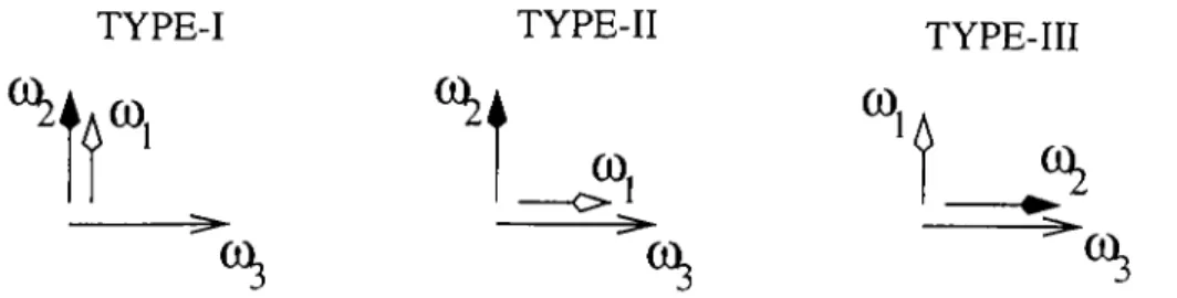
In materials exhiljiting normal dispersion, the highest frequency wave of the interaction has to be polarized along the fast axis of the crystal, the axis with the lower refractive index. The remaining possibilities for the direction of polarization of the two lower frequency waves lead to three different types of BPM. In this thesis, we follow the convention that the fields are la.beled according to u)\ < u
)2
< LV3
. In type-I BPM, both the lower freciuency waves at u>i and u>2
are polarized along the slow axis, whereas in type-II (III) BPM, the lowest frequency wave at u7
] is along the fast (slow) axis and the remaining wave at u)2
is along the slow(fast) axis. These possibilities are sumniiu'ized in Table
2.1
and Figure 2.1.Type 073 ^ U
7
i -f-072
I / ^ ,s + ,s II ./■ ^ ./■ + ·^· III ./■ + ./■
Table 2.1: Potential phase matching types for BPM of second-order iionlim'ar interactions. Normal dispersion is assumed. The fast and slow axes are denoted by / and s, respectively.
2.3.2
Quasi-phase matching
Quasi-phase matching (QPM ) is achieved in most cases by employing ])eriodic domain reversals in feiroelectric crystals [24]. These domain revcnsals lead to a
TYPE-I TYPE-II TYPE-III
t
(
0
.CO.
Figure
2
.1
: Polarization geometries lor BPM types. The fast axis is liorizontal and the slow cixis is vertical.periodic modulation of the sign of the effective nonlimxu· coefficient. The nonlin ear coefficient then becomes a periodic function of and can be represented by a Fourier series
d{z) = d, ^ GVP*··"·' (2.24)
where G, = i\ and A is the period of the modulation. In QPM, a particular spatial harmonic of tlie modulation compensates for the phase mismatch [24] and k'i — k
-2
— k'l — kn becomes zero. The order n of this spatial harmonic gives a degree of freedom for phase matching. If the non-phase matched harmonics are ignored, the effective nonlinear coefficient of the quasi-phase matched interaction is equal to d,,Gn· With QPM, the highest frequency field of the interaction does not have to be polarized along the fast cixis of the crystal anymore, and the number of potential phase matching types becomes eight. However, QPM is usually achieved with all fields polarized along the same direction, to take advcuitage of a large diagonal element of the second-order nonlineai' susceptibility tensor \When the nonlinear coefricient is modulated by periodic sign reversal.
G'„ = --- sin(
7
rnl') J?.7T(2.25)
where
1
' = /q/A is the duty cycle and Iq is the length of the reversed domainin a single period [24]. The largest possible nonlinear coefficient is obtained l^y first-order QPM with 50% duty cycle and is equal to
2
j d j n .2.4
Optical parametric amplification
In an OPA, an intmisi; field at cu
3
amplifies a weak field at either u>[ oi' LO2
. If either one of the lowei' frequency fields at u>i or u>2
is not j:)resent initially, that field is generated in the interaction. In OPA terminology, the intense field at u>:\ is called the pump, the amplified field is called the signal, and the generated fieldis called the idler. In this thesis, we assume for definiteness that the signal is at oo-i- However, the results presented below are equally valid if the signal is at uo\.
In any second-order nonlinear interaction, the lack of one of the three inter- cicting waves at the crystal input leads to field solutions whose intensities are independent of the relative ¡diases of the two input fields. In an OPA, the idler field is absent at the crystal input, and the generated idler field adjusts its phase to match the phase difference between the pump and the signal. To show this result analytically, the coupled mode ecpiations for the complex field cimplitudes [Elquations (
2
.20
) - ( ‘2
.22
)] are first converted to equations lor real field amplitudes cuid phases. We also normalize the real field amplitudes so that their squares correspond to photon flux densities. The transformation from the complex field cunplitudes to real amplitudes a,i and phases for a phase matched interaction is'
2
hu>; A,The resulting real ecpiations are dill -an: riiCi
.0
dz d(l2
H da-i dz dip = —/vaa3
rt2
sm (p= —/vn,a
3
«i sin (y?= Kaiiitt^sini/?
K.„ ai(i
2
(Hii'i rti«3 cos ip(2.26) (2.27) (2.28) (2.29) (2.;10) «3
«1
a2
where ip =
(/>3
— (j)2
—'/’1
[21
]· In these equations, thei'e is only a single coupling constant for the interaction/v,, d(^
1
2
h luJ]L02
iO:\c ' h o V ? i l ' » - 2 ' " 3
( 2. ; l l )
Substituting the real amplitude equations (2.27)-(2.29) into the plia.se equa tion (2.30) gives
dip cos <p d
ln(ai«2«3). (2.32)
dz sin ip dz
It ma.y b(' verified liy direct diffen-entiation that this equation can be rewiltten as d
dz ln(rtirt
2«3
cost/?) =0
. (2..33) fh'iHX'. « i «2
rt3
Cosi/? is a conserved quantity; it does not depend on the propa.gation distance ;·. If one of the three fields has zero am])litud(' at l.he crystal enti'ance.this quantity has a constant value of zero. Since the field that is not present initially is generated in the interaction, ip has to be equal to ± 7t/ 2 throughout the interaction so that coup — 0. In an OPA, the generated idler acquires a phase that makes p equal to —-k¡'I. In this case, the coupled mode equations that describe the interaction are
(Icii 1 7 (2.34) da
2
dz K-aXlsai (2.35) das dz (2..36)In terms of the quantum mechanical picture of second-order nonlinear interac tions, when a signal photon is created, a pump photon is annihilated and an idler photon is created [19], [20]. The Ma,nle_y-Rowe relations express the conserved quantities
6
’i — af{z) + al{z) — «3
(0
)0-2
= a^^{ z) a^^{ z) = a.^(0
) + «3
(0
)(2.37) (2.38)
in terms of the photon flux densities [19], [20]. These quantities can be used to transform the coupled mode equations for an OPA [Equations (2.34)-(2.36)] to a single differential equation which can be integrated to obtain the solutions for field amplitudes in terms of .Jcicobi elliptic functions. We define a new variable
0
[z) througha\[z) = yC'i cosfl(.~) (2.39) (2.40)
Since no idler is present at the crystal input, fl(0) is equal to an odd multiple of
7
t/2
; for convenience, we choose 11(0) = tt/2
. Substituting into Equation (2.34),the signal field amplitude is obtained as
1
dO «2
(c) = --- - .K.,, dz (2.41)
We then substitut.e Equation (2.41) into the Manley-Rowe relation for C
2
[Equa tion (2.38)] to get a single differential eriuation2
in the variable 0{z). W hen integrated, Equation (2.42) give.s
rO
J TV// 7t/ 2 (2.43)
wliere nia =
6
’i/C '2
. Tlii.s integral can be expressed in terms of the clli|)tic integrcd of the first kind [26], whose inversion l(!ads to .Jacobi elliptic functions. The integral first has to be i>ut into a slandard elliptic integral form so that its lower limit is zero. This leads torO (2.44) fO , / (1 - m„sin'fo/>)"^/'fo
/'0
= K(m.a) - k„\/C2
Z - Z„ Jo ^ where K { n i a ) =I
(1
-
???asin'"^
■(/’ )(
2
.
45
)
is the complete elliptic integral of the first kind, and is also the qiuirter-period of .Jacobi elliptic functions[
26
].
The angle6
, whose value at the crystal output is unknown, is called the amplitude and ???.„ is called the parameter in elliptic function terminology[
26
].
The Jacobi elliptic function sn is defined in terms of the cimplitude 9 as sn(Z„|m„) = sin<?. We then obtain the solutions for the field amplitudes asa^{z) = y C i cn(Z„,|/
7
?.„) (2.46) (h{z) = y / ^ d n ( Z j m „ ) (2.47) (isiz) = ^/C¡ Sn{Za\nia) (2.48) where the Jacobi elliptic functions cn and dn are defined as cn(Z„ = cosd and dn(Z(,,|??i.(i) =1
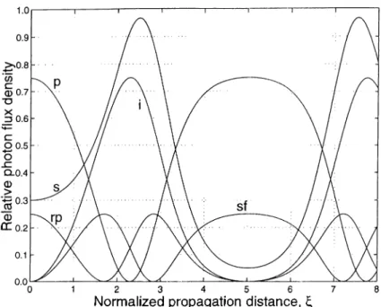
— m.aSn^{Za\ma); respectively.Figure
2.2
shows the evolution of the photon flux densities in an OPA, cojn- puted using the solutions (2.46)-(2.48). The photon flux densities are normalized to the incident pump photon flux density « 3 ( 6 ) . We define a dimensionless normalized propagation distance ^ so that tlie results are [)resented in a more general fashion. F'or this example, the input signal photon flux density is 0.25 times the input pump photon flux density, and therefore, ni„ = 4/5. .As shown in Figure 2.2, the signal field is amplified in the interaction until the pump field is fully depleted. At this point, the argument Z„, of the Jacobi elliptic func tions becomes equal to zero [26]. Afterwards, the interaction reverses direction, and the signal photons combine with the idler photons to regenerate' the pumj). This SFC process is called back-conversion. The interaction continues in this fashion and the thi'ee fields exchange energy periodically as they propa.gate in the nonlinear crystal.
F'igure 2.2: The evolution of the pump, signal, and idler photon flux densities in an OPA as functions of the norniiilized propagation distcince All photon flux densities are normalized to the incident pump photon flux density. The input signal photon flux density is 0.25 times the input pump photon flux density.
2.5
Optical parametric oscillation
An OPO is constructed by placing the OPA crystal inside a resonator. If the resonator mirrors reflect only at the signal frequency, the OPO is singly-resonant. Singly-resonant O P O ’s are preferred to doubly-resonant O PO ’s (in which both the signal cind the idler are resonated), ]rrimarily because the phase-insensitive OPA interaction in a singly-resonant OPO results in stable operation. However, doubly-resonant O P O ’s hcive a significantly lower threshold pump intensity. They are therefore employed if the available peak pump intensity is limited.
In a singly-resonant OPO, one of the mirrors is
9
. partial reflector at th(' signal frequency in order to couple the signal out of tlu’ resonator. If tlu' small- signal (unsaturated) gain is larger than the total cavity loss (output coupling and parasitic useless losses combined), oscillation starts and the signal field intensity starts to grow. The initial signal intensity is usually provided by spontaneous parametric fluorescence [27], not by a laser at the signal frequency, d'he OPO reaches steady-state when the saturated signal gain compensates for the loss exactly. The steady-state oscillation condition is, «
2(0
R
Figure 2.3: The iiitracavity signal flux density of an OPO is found l:)y the inter section of the gain saturation curve and the resonator loss line (of value 1/R). For this example, the nonlinecir drive of the OPO is unity and the lumped resonator reflectance R = RocRl is 0.9. The signal flux density is normalized to the input pump flux density.
where R. — RqcRl] Roc is the reflectanc(; of the output coupler, /?l is a lumped reflectance representing useless losses, and / is the crystal length.
To find the intracavity signal photon flux density (/-
2
(0
), in general one has to solve Equation (2.49) iteratively using a numerical root-finding algorithm. In this thesis, the secant method is used for finding the root of the function /[o-liO)] =7
?a2
( / ) / «2
(0
) — 1. The .secant method starts with two initial guesses on «2
(0
). At each iteration, the saturated signal gain g = d2
i^)la\{Q) is calculated using the single-pass solutions [Ec(uations (2.46)- (2.48)] and the next ai)proximation to «2
(0
) ta.ken to Ire the zero-crossing of the line that passes tlirough the two previous approximations [28]. The algorithm stops when the difference Iretween the last two approximations is less than a specified tolerance.F'dgure
2.3
shows an example of gain saturation for the signal field as a. function of the intracavity signal photon flux density. The gain saturation in an OPA is com|)letely chcu-acterized by the dimensionless paramet(?r I) = [a:,,('/.3
(0
)/]^, called the nonlinear drive [10], [23], [17]. The nonlinear drive is a measure of the strength of tlu' interaction. In Fdgure 2.3, the noidinear drive is chosen to be unity and this results in a small-signal gain of 2.4.In the small-signal regime, the depletion of the pump field is negligible. There fore, the small-signal gain go can be obtained by solving the coupled mode equa tions [Equations (2.34)-(2.36)] with
«3
taken to be constant. In this regime,α·
2
{ζ) = «2
(0
) cosh[K,,a3
(0
).:] (2..30) and the small-signal gain is go ~ cosh^(\/Z)). The threshold nonlinear drive Dti, can l>e found by solving Rgo = 1 lor D.Also shown oil Figure 2.3 is a loss line representing a resonator loss of R =
0
.9
. The intersection of the gain saturation curve and the loss line gives the intracavity signal flux density. For this example, the intracavity signal flux density is4.8
times the input pump flux density. Once the intracavity signal flux density is known, the field amplitudes at the cr\'slal output can be calculated using the single-pass solutions [Equations (2.46)-(2.48)].
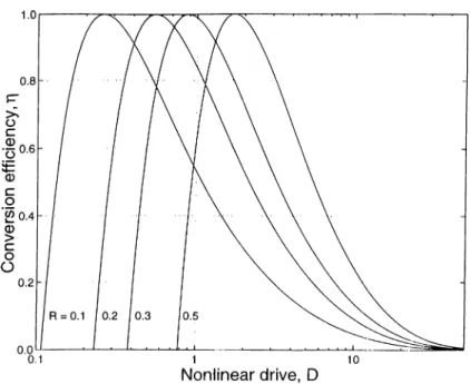
The performance of an OPO is characterized by the photon conversion effi ciency (also called the ([uantum efficiency [10], [23])
{ i - R o c ) a l ( l )
a m (2..51)
the ratio of the signal photon flux density coupled out of the Ccwity to the input pump photon flux density. Figure 2.4 shows the conversion efficiency of the OPO as a function of the nonlinear drive for four different values of the output coupler reflectance Roc- each case, R^ =
1
. The OPO can be very efficient, with conversion efficiencies reevching100
% for ])articula.r values of the nonlinear drive. These maxima of conversion correspond to complete depletion of the pnni]). If the nonlinear drive is increased still further, the convei'sion efficiency drops because of ba.ck-conversion. Note that for a given value of the nonlinear drive, the out])ut coupler reflectance can l)e o|)timized for maximum conversion [10], [23]. Figure2.3
shows the dependence of the optimum Roc on the nonlinear drive. The optimum Rqc decreases monotonically with increasing nonlinear drive.
2.6
Sum-frequency generation
In SFG. a lower IVequency in[)ut field at and a higher frequency input field at tur, interact to generate their sum-frequency at u-Vj = u-m -f a.’
5
. .As in the OPA case, the lack of a snm-frequency field at tlie crystal in|)ut leads l.o phase- insensitive field solutions; the generated sum-frequency field acqulix's a phase soFigure 2.4: Photon <'onversion efficiency of the OPO as a function of the nonlinear drive fo)· four different values of Roo- Rl is taken to he unity.
F'igure
2
.5
: Optimum output coupler rellectcmce R oc hu' fhe OPO as a function of the nonlinear drive. R\^ is taken to be unity.that φ — φα — Φγ, interaction are
φ,^ =
7
t/2
. The coupled mode e(|uations that govern theda.{ dz dur, 1 7 dz (2.52) (2.55) 1 6
with the coupling constant da^ dz Kb = df — /v lyCti^Ct
5
I 2h C^Cq LO:\iOr^iOQ (2.54) (2.55) n.-iUrJlGThe solutions lor the SFCJ i)rocess are in terms of .Jacobi elliptic functions as in OPA’s. However, the SFG solutions clei)encl on which of the two input fields lias smaller photon flux density at the crystal input. The interaction reverses direction when the field with the smaller photon flux density is fully depleted inside the crystal, and back-conversion (parametric amplification) begins. If a|(0) > «¡(0 ), the solutions are [17]
«
4
(2
:) = dn{Zb\rni,) (2.56) «s(^) = \ / ^ cn(Zb\rnb) (2.57) «g('~) = \/G2
sn{Zb\rnb) (2.58) (2.59) (2.60) (2.61) (2.62) whereCl = al(z) + (il{z) == aliO) C, = 4 i ^ ) + 4 i z ) = aliO) are the Manley-Rowe conserved quantities and
Zb = ^hy C\ z
C2 rn, = - .
The solutions lor the case «
5
(0
) > «¡[(O) are olrtained by interchanging the field subscripts 4 and 5 and the Manley-Rowe subscripts1
and2
.Figure 2.6 shows the evolution of photon flux densities in SF(1 for the cas(' ai](0) > «
5
(0
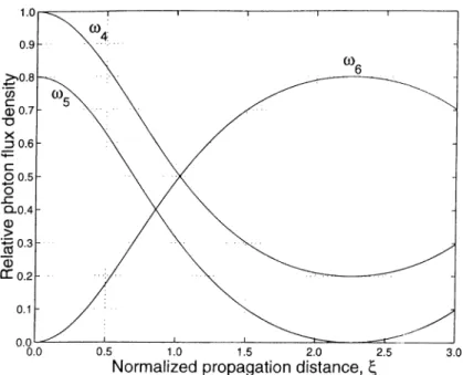
). All photon flux densities are normalized to «¡((O). The higher frequency SFC input field is completely depleted at Zb = 2.3, at wliich point tlu' sum-fre(iuency photon flux density reaches its maximum value. After this point, back-conversion of the sum-frequency to the SFG! input fields Ijegins and tlie SF(! photon flux density decreases.2.7
Second-harmonic generation
In SHG!, an incident field at u leads to the gemoration of liglit at
2
u>. 'I’he inci dent field at u is called the fundamental and the generated field at2
lv is calledFigure
2
.6
: The evolution of the lower frequency SFG input (a.i), higher frequency SF'G input (as), and suni-frequency (ae) photon flux densities as functions of the normalized propagation distance G All photon flux densities are normalized tothe second-harmonic. SHG can also be viewed as SFG degenerate in frequency (cû
4
— u-’s = cu). However, the phase matching type may require the fundamen tal field to have two components polarized along orthogonal eigenmodes of the crystcd. In type-II phase matched SHG, the fundamental field is nondegenerate in polarization. In other words, the fundamental has two orthogonally polar ized components (I4
and05
. In this case;, the coupled mode equations are tlu' same as the equations for SFG [Elquations (2.52)-(2.54)]. The usual practice in non-degenerate SHG is to orient a linearly polarized fundamental field at a 45° angle to the two eigenpolarization directions since maximum conversion to fhe si'cond-harmonic takes place if the incident fundamental components have the same photon flux density. For this orientation, the SHG process becomes de generate and this degeneracy reduces the number of coupled mode equations to two [19].In type-I phase matched SHG, the fundamental field is degenerate in both frec|uency and polarization; the fundamental field is polarized along the slow axis of tli(' ciystal and it cannot be decomposed into two disl.inct fields corresironding to u>,i = ca and u>r^ = co. In terms of normalized real field amplitudes, the equations
that govern degenerate SHG are
with the coupling constant
da,\ clz düß t'X'i) — df> — —K\)CißCL\ -Kiya\ (2.63) (2.64)
2
h / 2u;3c'^Co V
(2.65)where is the fundamental at lo and ciq is the second-harmonic at 2a;. The solutions to this set of equations are [19]
where
04
(2
) = rti(0
).sech(f aQ{z) —■ ^ f i4
(0
)tanhi^ v2
(2.66) (2.67) (2.68)is the normalized propagation distance. There is only one Manley-Rowe conserved fluantity for SHG, and this quantity
(^’1
— +2
ag(.s) — a^,(0
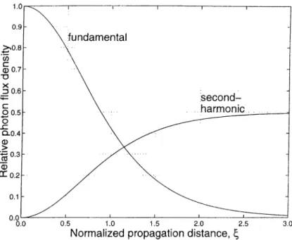
) (2.69) is proportional to the total intensity in the interaction.Figure 2.7 shows the evolution of the photon flux densities along tlie direc tion of propagation inside the crystal for SFIG. Both photon flux densities are normalized to the incident fundamental photon flux density. In contrast to other second-order nonlinear intei'cictions, the photon flux densities do not evolve peri odically in degenerate SHG. The second-harmonic photon flux density increases monotonically, and all of the input fundamental flux density is converted to tlu' sccond-harmonic in the limit of infinite interaction lentith.
Figure 2.7: The evolut.ion of the furidainental and the second-hannonic photon flu.x densities in SHC as functions of the normalized propagation distance Both photon flux densities are normalized to the incident fundamental photon flux density.
Chapter 3
Simultaneous Phase Matching of
OPO and S F G /S H G
Single-crystcil upconversion O P O ’s are based on the premise that two second- order nonlinear intc'ractions can be phase matched for the same direction of propagation inside the same crystal [29], [30]. For frequency upcom^ersion with an OPO, the second nonlinear interaction has to be either SHG or SFG. Upcon version with the OPO is more efficient if the SFG or the SHG processes take advantage of the high intensity of the resonant signal field.
The simultaneous phase matching condition can be? satisfied by either L3PM or QPM of the two processes. Various combinations of phase matching types of the two processes lead to several classes of upconversion O P O ’s, each governed by a different set of coupled mode equations. Some of these classes require a polarization rotation for the signal or the pump fields.
Simultaneous phase matching of two second-order intercictions within a single nonlinecU' crystal lias been experimentally demonstrated for a number of frequency conversion applications. Single-crystal upconversion O P O ’s that employ simulta neous BPM of frequency doubling [
8
] or SFG [9] in KTiOPO,| (K T P ), and period ically poled lithium niobate (PPLN) O P O ’s with simultaneous third-order QPM of frequency doubling [31], [32] or SFG [33] have been reported. A cascaded OPO, where the signal of a primary OPO acts as the pump for a secondary OPO, has been demonstrated in PPLN with fii'st-order QPM Idi' both OPO processi's [34]. Simultaneous SFG of the pump and the idler in a /4-barium borate (B130) crys tal OPA has been acliieved with BPM [33]. Simultaneous SFG with BPM has also been reported in an ADP crystal parametric fluorescence ex|)erinu'nt [36].Third-harmonic generation in PPLN with simultaneous first-order QPM of the frequency doubling and SFG processes hcis also been demonstrated [37].
For each combination of phase matching types for the OPO and SHG/SFG processes, the respective coupling constants «·,, and k/, depend on the phase- matched frequencies, the refractive indices, and the eilbctive nonlinear coefficients. The ratio of the two coupling constants β — κ.ι,Ικ„, is an important quantity that may assume a range of values depending on these parameters. Here, the relative magnitudes of the frequencies and effective nonlinear coefficients are of particular importance. If the OPO and SHG/SFG processes are of the same BPM type, the effective nonlinear coefficients differ only due to dispersion of the second- order nonlinearity [38]. However, for different phases matching types the effective nonlinear coefficients may be dramatically different from each other.
If QPM is cni])loj'ed for simultaneous phase matching, the QPM order of the two processes may or may not be different from each other. Since the effective nonlinear coefficient for a process depends on the QPM order as well as the other parameters mentioned above, choosing different QPM orders for the two processes provides a. mechanism for adjusting the value of β. The results of Chapter 5 show that having some control on the value of β can be very useful in maximizing the conversion efficiency of single-crystal upconversion O P O ’s.
Note that QPM can easily be used to ])hase match two interactions in a single crystal by employing two consecutive sections with different poling periods. Such a double-grating PPLN was recently used for intracavity SFG of an OPO [39]. Howevei', these double-grating devices ar<i identical to upconversion O P O ’s with two different crystals in terms of the plane-wave theory [18], [17].
3.1
Simultaneous phase matching of O PO and
SFG
We first present the possible combinations of BPM types for O P O ’s with simul taneous SFG. These combinations lead to four different classes of sum-frequency generating O P O ’s (SF-O PO’s), some of which require a polarization rotation foi' the signal or the pump fields. QPM opens up several more possibilities of |)ha.se matching type combinations, yet, each of these combinations Ccin be identilied with OIK' of the four Sf'-OPO classes.
3.1.1
Biréfringent phase matching
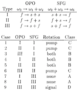
There are nine possible combinations of BPM types for the OPO and SPG pro cesses. These comlrinations are summarized in Table -i.l and Figure 3.1. In this thesis, the resonant signal field, which also constitutes the lower frequency input field for the SPG process, is labeled as being at u>
2
. However, our formulation and results are equally valid if the field at ωγ is resonated and used as a SPG input.OPO SPG
Type 0^3 —>CUi + U
2
^ 2
+ ^3 I • .s -f s .s + .sIf ./■ - ./■ +
Iff ./■ - S + ,/■ ■^· + /
Case OPO SPG Rotation Class
1
I1
pump C2
If I pump C 3 Iff I both B 4 I If both B 5 If If both B6
Iff II pump c 7 I III none A8
If III none A9 Iff III signal D
Table 3.f: Possible combinations of BPM types for OPO with simultaneous SPG. iNormal dispersion is assumed. The fast and slow axes are denoted by / and ,s. respectively.
In cases 7 and
8
, the pump and the signal fields are polarized along the same axes in both the OPO and SPG processes. As a. result, the two ])rocesses liecome coupled through the signal and the pump fields. The set of coupled mode equations that describe this interaction areda I ~cL· dü
2
~L· da-,i dz d(iß dz - «aö.S«2
— /vfj CL j CL2 L\’/)C l{)C l2 = κ,},α2
θ’Λ. (3.1) (3.2) (3.3) (3.4) •23ΟΡΟ
Η λ; I ΗII
i
- οIII
SFG
ISFG
II Φ Αsf
rs
I f ^
---^sf
rPA
rs
■ ■ P A ir s ^ ® Φ Α ^ ®^ s
SFG
III Hsf
s ^ ®P
rSA ®^ P
sf
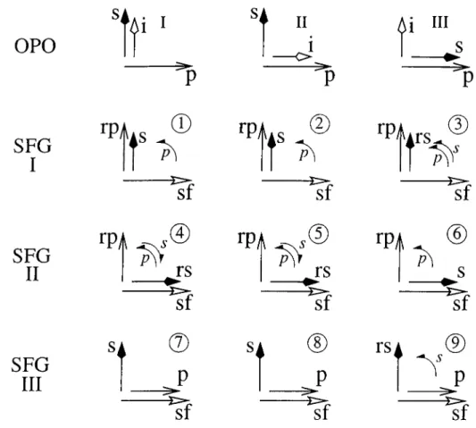
Figure 3.1: Polarization diagram.s for possible combinations of BPM types in SF- O P O ’s. Tlie fast a.\is is horizontal and the slow axis is vertical. Pohirizations for the pump (p), signal (s), idler (i), polarization rotated pump (rp), polarization rotated signal (rs), and sum-frequency (sf) are shown. Intracavity polarization rotation is indicated with an arc. Elach combination of phase matching types is lal)eled with a circled number.
We arrive at these equations by combining the OPA equations [Equations (2.34)- (2.36)] with the SE'C equations [Equations (2..52)-(2..')l)j. The signal U
2
(pump a-j) and the lower frequency SFG input a,i (higher frequency SE'G input0
,5
) aro' the sa.me field mode; the rate of change of the signal (pump) field amplitude is the sum of the rates of change of the OPO signal (pum]>) and the lower (higher) fre(|uency SFG input field amplitudes separately. Tlu' same equations can also Ire olrtained by considering the total nonlinear polarization P2
fi-ncl/3
at tU2
andresirectively, and re-deriving the coupled mode equations. We designate this SE'-OPO process as class-A.
In cases
3
,4
, and5
the jrurnp and signal fields are both oi-thogonally ¡rolarized between the OPO and SFG processes. The same crystal can be used for froth piocesses at the same time through extracavity polarizal.ion rotation ol the pump and intracavity polarization rotation of the signal. However, the two jrrocessesare not coupled in the crystal as they are in class-A interactions, and the coupled mode equations that govern this SF-OPO are simply Equations (2.34)-(2.36) and (2.52)-(2.54). We designate this SF-OPO as class-B.
In cases
1
,2
, and6
, the pump field is pohu'ized orthogonally between the OPO and SFG processes. A polarization rotation of the pump at the cavity input is required for SFG to take place. The signal field is common to both processes, and couples them to each other. The set of coupled mode ec|uations that describe all three cases aredii\ dz dci
2
dz dci:i dz dus dcic, dz ^ a 3 2 /v fj CL 2 CL j h\j }jCL(y (L ^ ^ a. ^ 1 2 = —KfjClC)Cl2
= Kl,a2
CLrj . (3.5) (3.6) (3.7) (3.8) (3.9)We designate this SF-OPO process as class-C.
In case 9, the signal is orthogonally polarized between the OPO and SFG processes, and an intracavity polarization rotation of the signal is necessary. The OPO and SFG processes are coupled to each other through the pump, which is common to both processes inside the crystal. The coupled mode equations that describe the interaction are
da I dz dü
'2
H das dz da,I 1 7 dae dz = Kaasai Κι^α,βα^ Kba:ia,i. (3.10) (3.11) (3.12) (3.13) (3.14)We designate this SF-OPO process as class-D.
3.1.2
Quasi-phase matching
In terms of simultaneous phase matching of SFG in an OPO, the eight QPM ]:>liase matching types lead to 64 different combinations. We found that each ol
these combinations can be identified with one of the four classes introduced abo\^e, depending on whether the coupling between the two pi'ocesses in the crystal is thiOugh the signal (chiss-C), the pump (class-D), both (class-A), or neither (class- B).
3.2
Simultaneous phase matching of O P O and
SH G
The possible combinations of BPM types for OPO with simultaneous SHG lead to three different classes of self-doubling O P O ’s (SD-OPO's). Two of these classes require a polarization rotation for tlu' signal field while the third does not. We also find that eiich of the possible combinations of QPM types can be identified with one of these three classes.
3.2.1 Biréfringent phase matching
There are six possible combinations of BPM types for the OPO and SHG pro cesses. These combinations are summarized in Tabh' ·Τ
2
and Figure3
.2
. The fundamental field for SHG is assumed to be the resonant signal field, since the high intracavity signal intensity leads to efficient SHG. For frequency upconver- sion with the SD-OPO, the signal field has to be at tu-i, so that2
ω·ί > ω-i can be satisfied.In cases
1
and2
, the OPO signal and the SHG fundamental are both polar ized along the same direction and the two fields cire indistinguislialrle in (‘very aspect. As a result, the two processes are coupled through the signal field which is common to the two jrrocesses. The coupled mode c(|uations that govern this interaction are dcii(3 . 1 5 )
d a-2(3 . 1 6 )
H=
K.^d'^ax-
K .}y(i^2 d (i:i ~dz = - κ ^ α χ α ι(3 .1 7 )
daa dz=
(3 . 18 )
where k„, and a/, are the coupling constants for the OPA and the SHG proco'sscis.
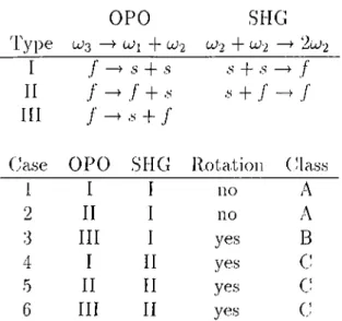
OPO SHG Type CJ
3
ωι + ω·2
ω·2
+ ω·2
—>2
u;2
I ./■ -ye + S .s + .s· ^ / II ■ j + .s .s + / ./■ III • + ./■
(.hise OPO SI-IG Rota.tion ( ¡lass
1
I I no A2
II I no A 3 III I yes B 4 I II yes c: 5 II II yes c6
III II yes GTable
3
.2
: Possible combinations of BPM types for OPO with simultaneous SHC. Normal clispei'siou is assumed. The fast and slow axes are denoted by / and s, respectively. There is no type-III BPM for SHG since this process is degenerate in frequency.OPO:
1I
HII
III
. sSHG:
I
SHG:
II
Hω
Λds
©
. rs
% H Λds
©
rs
T s
rs
%Figure
3
.2
: Polarization diagrams for possible combinations of BPM types in SD- O P O ’s. The fast axis is horizontal and the slow axis is vertical. Polarizations for the pump (p), signal (s), idler (i), polarization rotated signal (rs), and freciuency- doubled signal (ds) are shown. Intrcicavity polarization lotation is indicated witli an arc. Bach comihnation of phase matching types is labeled with a cii-cled number.respectively. We obtain these equations by combining the OPA e(|uations [Bqua- tions (2.34)--(2.36)] with the degenerate SHG equations [liquations (2.63) (2.64)].
We designate this SD-OPO process as class-A.
In case
3
, the polarizations of the OPO signal and the SFCl fundamental are orthogonal. However, an intracavity polarization rotation ol the signal provides the input field for SHG and allows the same crystal to be used for both processes at the same time. In contrast with class-A SI)-OPO’s, the two processes are not coupled in the crystal, and the coupled mode e([uations that, describe the interaction are simply Equations (2.34)-(2.36) and (2.63) (2.64). We designate this SD-OPO as class-B.In cases 4, 5, and
6
, the SHG process is nondegenerate in polarization, and there are two orthogonally polarized fundamental components. The OPO signal is polarized along either component of the fundamental in each case, and the two processes are coupled through this component. An intracavity polarization rotation of the signal field provides the second fundamental component and makes SHG possible. 'I'he coupled mode ecpiations that govern the interaction arecUii dz (3.19) dü
2
dz — f\· Q CL 3 CL L\· CL(yCL (3.20) c/a.3
dz — a 1 2 (3.21) dcir^ dz — L C h ( L (^ C L 2 (3.22) dciQ = K .i) C L 2 C L r y . (3.23)These e([uations are obtained by combining the OPA e(|uations [Eciuations (2.34)- (2.36)] with the uondegenerate SHG equations [Equations (2.52)-(2.■54)]. We desigimte this SD-OPO as class-G. Note that Equations (3.19) -(3.23) a.re the sanu' as the coupled mode equations that govern class-G SE-OPO’s [Equations (3.5) (3.9)].
3.2.2
Quasi-phase matching
Since; the SHG ])rocess is degenerate in frec|uency, tli<;re are only six possible QPM types for SllG as opposed to eight for the OPO. In terms of simultaiK'ous phase matching of SHG in an OPO, the potential QPM typ<;s lead to 48 different combinations. We found that each of these combinations can be identified with one of the three classes introduced above, depending on whether tlu' SHG ]>rocess is nondc'generate in polarization (class-G) and il not, whether the polarizations
of the ΟΡΟ signal and the SHG fundamental are orthogonal (class-B) or not (cl ass-A).