PHYSICAL INTEGRATION OF CHEMICAL LOGIC GATES
A THESIS
SUBMITTED TO THE DEPARTMENT OF CHEMISTRY
AND THE GRADUATE SCHOOL OF ENGINEERING AND SCIENCE OF BILKENT UNIVERSITY
IN PARTIAL FULFILLMENT OF THE REQUIREMENTS FOR THE DEGREE OF
MASTER OF SCIENCE
By
ŞEYMA ÖZTÜRK July, 2012
I certify that I have read this thesis and that in my opinion it is fully adequate, in scope and in quality, as a thesis of the degree of Master of Science.
………. Prof. Dr. Engin U. Akkaya (Principal Advisor)
I certify that I have read this thesis and that in my opinion it is fully adequate, in scope and in quality, as a thesis of the degree of Master of Science.
………. Assoc. Prof. Dr. Dönüş Tuncel
I certify that I have read this thesis and that in my opinion it is fully adequate, in scope and in quality, as a thesis of the degree of Master of Science.
………. Prof. Dr. Adil Denizli
Approved for the Graduate School of Engineering and Science: ……….
Prof. Dr. Levent Onural
i
ABSTRACT
PHYSICAL INTEGRATION OF CHEMICAL LOGIC GATES
Şeyma Öztürk M.Sc. in Chemistry
Supervisor: Prof. Dr. Engin U. Akkaya July, 2012
Recent research in molecular logic gates produced molecular equivalence of highly complex digital designs. Advanced data processing at the molecular level requires a considerable degree of integration (concatenation) between molecular logic gates. So far, almost all the integration reported in the literature has been “virtual”, meaning that the outputs at various channels are determined first and then an integrated set of logic gates is proposed to be operating on inputs to produce those outputs. Nevertheless, there is no doubt that at some point there has to be methods to physically connect one molecular logic gate to the other one, for a rational design and implementation. In this study, we synthesized a few derivatives of the well known fluorophore “Bodipy” and then proposed two methodologies to concatenate separately existing and functioning Bodipy-based chemical logic gates. In one instance, we coupled a photochromicity-based AND gate to an ion-responsive Bodipy-based AND gate, making use of the modulation of inner filter effect. In the other example, we coupled two ion-responsive Bodipy-based AND gates through the increased efficiency of energy transfer and “click” chemistry. We are certain that these methodologies are highly promising and our studies are in progress to demonstrate more complex examples of physical integration.
ii
ÖZET
MOLEKÜLER MANTIK KAPILARININ FİZİKSEL
ENTEGRASYONU
Şeyma Öztürk
Kimya Bölümü, Yüksek Lisans Tez Yöneticisi: Prof. Dr. Engin U. Akkaya
Temmuz, 2012
Moleküler mantık kapıları ile ilgili son zamanlarda yapılan araştırmalar, gelişmiş dijital devrelerin moleküler eşdeğerlerinin yapılabileceğini gösterdi. Moleküler seviyede bilgi işlem, moleküler mantık kapıları arasında entegrasyon gerektirir. Bu zamana kadar literatürde yer alan entegrasyonların neredeyse tümü ‘sanal’ nitelik taşır. Yani; ilk olarak çıktılar üzerinde karar verilir, daha sonra girdilerin üzerinde işlem yapıp o çıktıları üretiyormuş gibi davranan entegre edilmiş mantık kapıları tasarlanır. Fakat, rasyonel bir dizayn ve uygulama için, şüphesiz ki moleküler mantık kapılarını fiziksel bir yolla birbirine bağlayacak metodlara ihtiyaç vardır. Biz de bu çalışmada, moleküler mantık kapısı olarak kullanılmak üzere birkaç Bodipy türevi sentezledik ve onların fiziksel entegrasyonunu iki ayrı metodla gerçekleştirdik. Birinci yöntemde, fotokromik boya bazlı VE mantık kapısını iyona duyarlı Bodipy bazlı VE mantık kapısına entegre ettik ve bunu yaparken iç filtreleme etkisinin modülasyonundan yararlandık. İkinci örneğimizde ise, kimyasal bir reaksiyon (‘click’ reaksiyonu) ve enerji transferi vasıtasıyla, iki ayrı iyona duyarlı Bodipy bazlı VE mantık kapısını birbirine bağladık. Çalışmalarımız daha kompleks fiziksel entegrasyonları gerçekleştirmek yönünde devam ediyor.
iii
ACKNOWLEDGEMENT
I would like to thank my supervisor Prof. Dr. Engin U. Akkaya whose encouragement and support made this study possible. I also want to express my sincere appreciation to him for his guidance, teaching, and understanding during this research.
I would like to thank Ruslan Guliyev and Ziya Köstereli for their partnership in this research. I owe a special thank to Ruslan Guliyev for his support, friendship and guidance during this study.
I want to thank our group members Bilal Kılıç, Yusuf Çakmak, Sündüs Erbaş Çakmak, Onur Büyükçakır, Safacan Kölemen, Tuğba Özdemir, Tuba Yaşar, Tuğçe Durgut, Yiğit Altay, Ahmet Atılgan, Bilal Uyar, Fazlı Sözmen, Seda Demirel, Murat Işık, Esra Tanrıverdi, Nisa Yeşilgül, Elif Ertem, Gizem Çeltek, Fatma Pir, Ahmet Bekdemir, Muhammed Büyüktemiz, İlke Şimşek, Hatice Turgut, Hande Boyacı and Sencer Selçuk, for their valuable friendships, wonderful collaborations, and great ambiance in the laboratory. It was wonderful to work with them.
I want to express my gratitude to my family for their love, support, and understanding. I owe them a lot.
I would like to thank to TÜBİTAK (The Scientific and Technological Research Council of Turkey) for their financial support.
iv
LIST OF ABBREVIATIONS
AcOH : Acetic Acid
Bodipy : Boradiazaindacene CHCl3 : Chloroform DDQ : Dichlorodicyanoquinone DMF : Dimethylformamide ET : Energy Transfer Et3N : Triethylamine
FRET : Förster Resonance Energy Transfer HOMO : Highest Occupied Molecular Orbital ICT : Internal Charge Transfer
IFE : Inner Filter Effect
LUMO : Lowest Unoccupied Molecular Orbital MALDI : Matrix-Assisted Laser Desorption/Ionization
MS : Mass Spectroscopy
NMR : Nuclear Magnetic Resonance PeT : Photoinduced Electron Transfer TFA : Trifluoroacetic Acid
THF : Tetrahydrofuran
TLC : Thin Layer Chromatography TOF : Time of Flight
v
TABLE OF CONTENTS
CHAPTER 1: INTRODUCTION ... 1
1.1 Logic Gates: Building Blocks of Silicon Circuitry ... 1
1.2 Molecular Logic Gates: Computation with Molecules ... 3
1.3 Fluorescence Phenomenon ... 5
1.3.1 Basics of Fluorescence ... 5
1.3.2 Photoinduced Electron Transfer ... 8
1.3.3 Internal Charge Transfer ... 12
1.3.4 Energy Transfer ... 14
1.3.4.1 Förster Type Energy Transfer ... 15
1.3.4.2 Dexter Type Energy Transfer ... 17
1.4 Higher Functions with Molecular Logic ... 18
1.4.1 Half Adder/Subtractor ... 19 1.4.2 Full Adder/Subtractor ... 23 1.4.3 Multiplexer/Demultiplexer ... 26 1.4.4 Encoder/Decoder ... 30 1.4.5 Sequential Logic ... 32 1.4.6 Functional Integration ... 35 CHAPTER 2: EXPERIMENTAL ... 36
2.1 Methods and Materials ... 36
2.2 Synthesis of Target Molecule 1 (Compound 4) ... 37
2.2.1 Synthesis of Compound 1 ... 37
vi
2.2.3 Synthesis of Compound 3 ... 39
2.2.4 Synthesis of Compound 4 ... 40
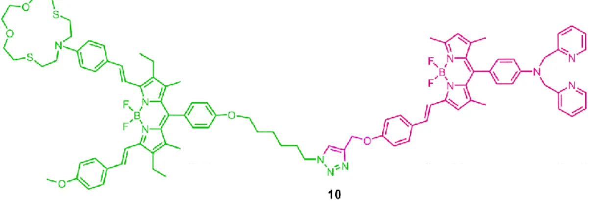
2.3 Synthesis of Target Molecule 2 (Compound 10) ... 41
2.3.1 Synthesis of Compound 5 ... 41 2.3.2 Synthesis of Compound 6 ... 42 2.3.3 Synthesis of Compound 7 ... 43 2.3.4 Synthesis of Compound 8 ... 44 2.3.5 Synthesis of Compound 9 ... 46 2.3.6 Synthesis of Compound 10 ... 47
CHAPTER 3: RESULTS AND DISCUSSION ... 49
3.1 Physical Integration of Chemical Logic Gates ... 49
3.1.1 First Approach: Photochemical Modulation of Inner Filter Effect ... 50
3.1.2 Second Approach: Increased Efficiency of Intra-molecular ET ... 59
CHAPTER 4: CONCLUSION ... 70
REFERENCES ... 71
APPENDIX A - NMR SPECTRA ... 79
vii
LIST OF FIGURES
Figure 1. Transistor counts for integrated circuits in 1971-201117 ... 3
Figure 2. First two-input molecular logic gate by de Silva et. al. (1993) ... 4
Figure 3. XOR & XNOR gate designed by de Silva and McClenaghan (2002) ... 5
Figure 4. Jablonski diagram showing transitions between the electronic states ... 6
Figure 5. Simple scheme for the Stokes Shift ... 7
Figure 6. Schematically representation of PeT mechanism ... 9
Figure 7. Fluorescence of the Bodipy is recovered when Zn2+ ions are added ... 10
Figure 8. Schematically representation of oxidative PeT mechanism ... 11
Figure 9. Coordination of Zn2+ ions triggers oxidative PeT mechanism ... 11
Figure 10. Schematically representation of ICT mechanism ... 13
Figure 11. Bidirectional switching of the dyes related to ICT characteristics ... 13
Figure 12. Förster type (through space) and Dexter type (through bond) ET ... 15
Figure 13. A Bodipy based Förster type energy transfer system ... 17
Figure 14. Anthracene-Bodipy based Dexter type energy transfer system ... 18
Figure 15. Ligand-metal based Dexter type energy transfer system ... 18
Figure 16. Half-adder logic diagram with truth table ... 19
Figure 17. First molecular half adder ... 20
Figure 18. Different ionization states of fluorescein on protonation/deprotonation .. 21
Figure 19. Fluorescein as a molecular half-adder ... 21
Figure 20. Half subtractor logic diagram with truth table ... 22
Figure 21. The first molecular half subtractor based on tetraphenylporphyrin109 ... 23
Figure 22. Full adder logic diagram ... 23
Figure 23. Absorption spectra for the forms of fluorescein117 ... 24
Figure 24. A full adder based on fluorescein molecule ... 25
Figure 25. A full subtractor based on fluorescein molecule ... 26
Figure 26. The structure (a) and photochemistry (b) of FG-DTE121 ... 28
viii
Figure 28. Performance of FG-DTE as 1:2 demultiplexer121 ... 29
Figure 29. The 4-to-2 encoder based on [Ru(bpy)3]2+ metal complex ... 31
Figure 30. The 2-to-4 decoder based on [Ru(bpy)3]2+ metal complex ... 31
Figure 31. General representation for sequential logic circuit ... 32
Figure 32. The osmium polypyridyl complex used in the study ... 33
Figure 33. Schematic representation of SR latch ... 34
Figure 34. DTE photoelectroswitch assembled on a gold electrode ... 34
Figure 35. Synthesis of Compound 1 ... 37
Figure 36. Synthesis of Compound 2 ... 38
Figure 37. Synthesis of Compound 3 ... 39
Figure 38. Synthesis of Compound 4 ... 40
Figure 39. Synthesis of Compound 5 ... 41
Figure 40. Synthesis of Compound 6 ... 42
Figure 41. Synthesis of Compound 7 ... 43
Figure 42. Synthesis of Compound 8 ... 44
Figure 43. Synthesis of Compound 9 ... 46
Figure 44. Synthesis of Compound 10 ... 47
Figure 45. Compound 4 (Bodipy derivative) and thionine (photochromic agent) ... 50
Figure 46. Reversible photochemical conversion of thionine into leucothionine ... 51
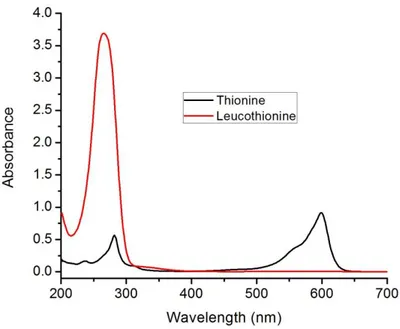
Figure 47. Absorption spectra of thionine and leucothionine (12.5 µM each)... 52
Figure 48. Transmittance spectra of thionine and leucothionine solutions ... 53
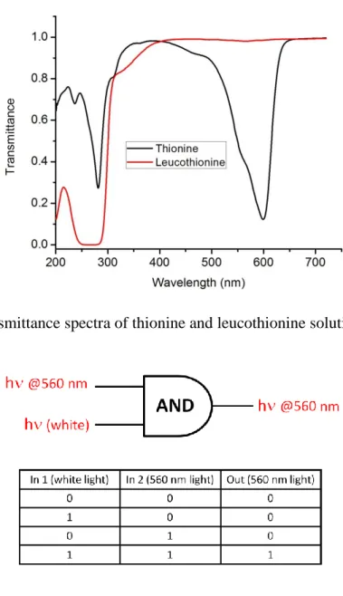
Figure 49. Schematic representation of first independent AND gate ... 53
Figure 50. Absorption spectra of the compound 4 solution (2.2 µM) in methanol .... 54
Figure 51. Emission spectra of the compound 4 solution (2.2 µM) in methanol ... 54
Figure 52. Schematic representation of second independent AND gate ... 55
Figure 53. A representation for the integration of AND logic gates ... 56
Figure 54. Operation of the integrated logic gates shown by the emission spectra ... 57
Figure 55. Reversibility between thionine and leucothionine. ... 58
ix
Figure 57. The first and second independent AND logic gates: 4 and 9 ... 60
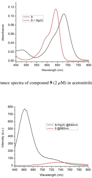
Figure 58. Absorbance spectra of compound 9 (2 µM) in acetonitrile ... 61
Figure 59. Emission spectra for compound 9 (2.0 µM) in acetonitrile ... 61
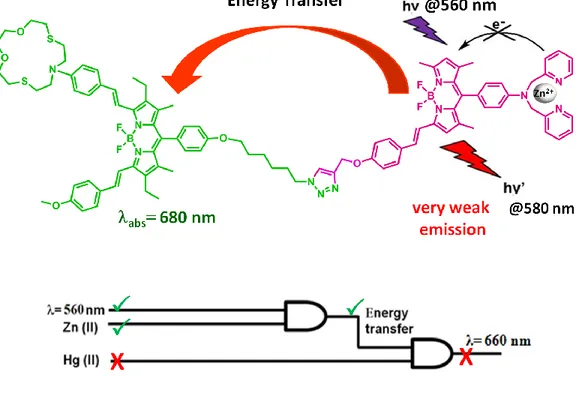
Figure 60. Possible energy transfer from donor to acceptor for 10 ... 62
Figure 61. The diagram for the integrated system (compound 10) ... 63
Figure 62. The dependency of high emission at 660 nm on PeT process ... 63
Figure 63. The inadequate spectral overlap between donor and acceptor ... 64
Figure 64. An efficient spectral overlap between donor and acceptor ... 65
Figure 65. Absorbance spectra of 10 (3.0 M) in acetonitrile ... 67
Figure 66. Emission spectra of 10 (3.0 M) in acetonitrile ... 68
Figure 67. The graphical abstract (above) and the cover picture (below) ... 69
Figure 68. 1H NMR Spectrum of Compound 1 ... 79
Figure 69. 1H NMR Spectrum of Compound 2 ... 80
Figure 70. 1H NMR Spectrum of Compound 3 ... 81
Figure 71. 13C NMR Spectrum of Compound 3 ... 82
Figure 72. 1H NMR Spectrum of Compound 4 ... 83
Figure 73.13C NMR Spectrum of Compound 4 ... 84
Figure 74. 1H NMR Spectrum of Compound 5 ... 85
Figure 75. 13C NMR Spectrum of Compound 5 ... 86
Figure 76. 1H NMR Spectrum of Compound 6 ... 87
Figure 77. 13C NMR Spectrum of Compound 6 ... 88
Figure 78. 1H NMR Spectrum of Compound 7 ... 89
Figure 79. 13C NMR Spectrum of Compound 7 ... 90
Figure 80. 1H NMR Spectrum of Compound 8 ... 91
Figure 81. 13C NMR Spectrum of Compound 8 ... 92
Figure 82. 1H NMR Spectrum of Compound 9 ... 93
Figure 83. 13C NMR Spectrum of Compound 9 ... 94
Figure 84. 1H NMR Spectrum of Compound 10 ... 95
x
Figure 86. Mass Spectrum of Compound 4 ... 97
Figure 87. Mass Spectrum of Compound 7 ... 98
Figure 88. Mass Spectrum of Compound 8 ... 99
Figure 89. Mass Spectrum of Compound 9 ... 100
xi
LIST OF TABLES
Table 1. Truth tables for common two-input logic gates ... 2
Table 2. Truth tables for full adder and full subtractor ... 24
Table 3. Truth table for the 4-to-2 encoder ... 30
Table 4. Truth table for the 2-to-4 decoder ... 30
Table 5. Truth table for the complex operating as an SR latch ... 33
1
CHAPTER 1
INTRODUCTION
1.1
Logic Gates: Building Blocks of Silicon Circuitry
Since the world’s entrance into the information age, computers and many other electronic digital devices have become essential part of our lives. They have already revolutionized society and business worldwide and certainly been required for global communication, sharing information, storing and processing data. Currently used computers and all other electronic digital devices make use of binary logic for data transmission, processing and storage, and they simply use electrical signals as information carriers. In those digital systems, information is encoded in series of zeros and ones that represent low and high voltage values1,2.
Logic gates3, known as electronic devices carrying out Boolean functions, are fundamental building blocks of silicon circuitry that all digital systems are based on. They process data by carrying out a logical operation upon one or more logical inputs and creating a single logical output. There are 16 possible two-input Boolean logic operations4 and 8 of them are commonly used in electronics: OR, AND, XOR, NOR, NAND, XNOR, INHIBIT (INH) and NINH. NOR, NAND, XNOR and NINH gates results from the concatenation of basic OR, AND, XOR and INH gates with “NOT” operation. The truth tables for all these logic gates together are shown in Table 1. In an OR gate, the output is 1 (the state above a specified threshold) when at least one of the inputs are 1. The output is 0 (the state below a specified threshold) only when both inputs are 0. In an AND gate, the output is 1 only if both inputs are 1; otherwise the output is 0 for any combination of inputs. For an XOR gate, the inputs set to different logic states yields 1 as the output. When both inputs are set to same logic state, the output is 0. In the INH gate, output signal is inhibited by one of the inputs.
2
For NOR, NAND, XNOR and NINH gates, the outputs are exactly the reverse of the ones in OR, AND, XOR and INH gates (Table 1).
INPUTS OUTPUTS
A B OR AND XOR INH NOR NAND XNOR NINH
0 0 0 0 0 0 1 1 1 1 1 0 1 0 1 0 0 1 0 1 0 1 1 0 1 1 0 1 0 0 1 1 1 1 0 0 0 0 1 1
Table 1. Truth tables for common two-input logic gates
There are also more complex logic systems that carry out higher functions. They are mainly formed by the integration of several of 16 fundamental logic gates. These circuits perform arithmetic and some other complex operations in binary fashion and yield bits of information. The most important ones for such circuits are half adder/subtractor, full adder/subtractor, multiplexer/demultiplexer, encoder/decoder and sequential logic5-6. They will be covered in detail later on (Section 1.4).
In conventional computers, a logic gate is constructed from transistors due to their capabilities to be used as electronic switches. The operation of a computer - the creation and manipulation of binary 0 and 1, basically occurs in its transistor. In a transistor, the current is switched by altering the gate voltage: the current is either turned off (0) or on (1)7. The invention of first silicon transistor in 19548 and ever since advancements in silicon-based semiconductor technology enabled the integration of large numbers of tiny transistors into a small chip. And, this has provided great improvements in electronics from performance, size and cost standpoints. Especially, miniaturization of electronic devices was the object of the integration of transistors. By the miniaturization of electronics equipment, increasing complex electronic functions were included in limited space with minimum weight. Miniaturization is still a key element for developing new technologies, however, according to Intel co-founder Gordon E. Moore’s predictions in 19659 and later
3
years10-15, it cannot continue forever. In nearly 2025, current technology is expected to come to a dead-end regarding miniaturization since the sizes of transistors are expected to reach to atomic levels16, which is a fundamental barrier.
Figure 1. Transistor counts for integrated circuits in 1971-201117
1.2
Molecular Logic Gates: Computation with Molecules
Since current integrated circuits technology is rapidly approaching its physical and technological limits, scientists have begun to think over potential alternatives in digital information processing. Among many proposals, molecular mimicry of logic gates has aroused a great deal of interest since the pioneering study of de Silva in 199318. Molecular and supra-molecular sensors are promising candidates as innovative materials in information processing.
4
Molecular logic relies on an ion-responsive molecule, which carries out a logical operation with one or more physical or chemical inputs. Fluorescence or a similar optical signal is usually the output of molecular logic gates. In 1993, de Silva et. al. reported the first receptor molecule (Figure 2) that operates as a logic device with two inputs18: when the molecule binds (selectively) both H+ and Na+ ions, its fluorescence intensity is greatly enhanced, otherwise it has a low fluorescence intensity. The input/output characteristics of this molecular logic device correspond to those of an AND gate.
Figure 2. First two-input molecular logic gate by de Silva et. al. (1993)
During the last two decades, a great progress has been accomplished in the field of molecular logic gates: a large number of molecular systems mimicking all 16 fundamental logic gates19-66 have been reported in the literature. For example, the first chemically driven XOR gate was demonstrated in 2002 by de Silva and McClenaghan44: The top of the molecule (Figure 3) containing four carboxylic acid anion groups is capable of binding Ca2+ cations. The bottom part is a receptor for H+ cations. When none of Ca2+ and H+ ions is present, the molecule displays absorption at 390 nm. Blue shift takes place in the presence of only Ca2+ ions while red shift occurs in the presence of only H+ ions. When both cations are present in the media, the molecule shows absorption at 390 nm again. This molecular system operates as
5
XNOR logic gate in terms of absorbance at 390 nm and XOR logic gate in terms of transmittance at 390 nm.
Figure 3. XOR & XNOR gate designed by de Silva and McClenaghan (2002)
A large number of molecular systems mimicking higher (complex) functions have also been demonstrated in the literature and they will be discussed later (Section 1.4). Molecular logic gates based on fluorescence phenomenon have been widely preferred so far due to the distinct advantages of fluorescence detection in terms of sensitivity and selectivity. Such systems, in which fluorescence switches between ‘on’ and ‘off’ states by chemical stimuli, are commonly designed according to a few principles like photoinduced electron transfer (PeT), internal charge transfer (ICT) and energy transfer (ET). For this reason, basics of fluorescence and fluorescence on/off switching mechanisms will be covered next.
1.3
Fluorescence Phenomenon
1.3.1 Basics of Fluorescence
Absorption of light by a molecule induces electron flow from its singlet ground electronic level S0 to an excited state Sn (n>1). That excited molecule returns to the
ground state S0 following two steps: First, the molecule at Sn returns to lowest excited
6
Then, the molecule at S1 returns to the ground state S0 via 4 different competitive
processes67.
Most important one among those four competitive processes is emission of a photon with a radiative rate constant and it is called “fluorescence”. The other process is dissipation of absorbed energy as heat and this kind of energy is non-radiative. Another process can be energy transfer from excited molecules to nearby molecules, which is usually known “collisional quenching”. The last one is the transient passage to the excited triplet state T1 (intersystem crossing) and then de-excitation of the
molecule from excited triplet state T1 to ground state S0. This phenomenon is called
phosphorescence67. All these processes are shown in Jablonski Diagram in Figure 4.
Figure 4. Jablonski diagram showing transitions between the electronic states
A chromophore that emits light is called fluorophore. The energy absorbed by a fluorophore is always greater than the energy emitted because total energy absorbed is released in the environment in several ways like photon emission. Such an energy loss results in a red-shifted emission spectrum. In other words, the maximum in the emission spectrum of the fluorophore is shifted to longer wavelengths compared to
7
the maximum in its absorption spectrum. This shift, which was observed in 1852 by Sir George Stokes, is called “Stokes shift”68 (Figure 5).
Figure 5. Simple scheme for the Stokes Shift
The position of the emission wavelength, the intensity and lifetime are important observables in the fluorescence spectrum that will characterize a fluorophore. Each fluorophore has different values for those observables. The wavelengths of absorption/emission maxima depend on the energy difference between the excited state S1 and the ground state S0 of a fluorophore. That energy difference can be
managed by some chemical modifications and non-covalent interactions. Thus, absorption/emission wavelength of a fluorophore can be modified.
Absorption and fluorescence are much faster processes than phosphorescence. Absorption occurs within a time equal to 10-15 s and the fluorescence lifetime is about 10-9 – 10-12 s while phosphorescence lasts from milliseconds to seconds, minutes, or even hours67. This is primarily because intersystem crossing and phosphorescence require spin reorientation (transitions between singlet and triplet states). Fluorescence lifetime simply means the average time during which molecules (after excitation) remain in the excited state before returning to the ground state and it is dependent on structure of the fluorophore.
8
Fluorescence lifetime, which is an intrinsic property, can be considered as a state function and hence does not depend on the method of measurement. It is independent of initial conditions like excitation wavelength and duration of light exposure. Furthermore, it is generally not affected by the concentration of the fluorophore and the emission intensity. On the other hand, since lifetime process is relevant to energetically unstable excited state, it is reasonable that lifetime is sensitive to some external factors such as temperature, polarity and the presence of fluorescence quenchers69. Fluorescence lifetime ( is inversely proportional to the sum of the rate constants of the radiative process (kf) and the nonradiative processes (knr). Based on
the assumption that fluorescence decays according to first order kinetics, lifetime is determined as follows:
= 1 / (kf + knr)The fluorescence intensity of a fluorophore is directly proportional to its quantum yield. The fluorescence quantum yield
F is number of photons radiatively emittedover number of photons absorbed by the molecule:
= photonsem / photonsabs = kf / (kf + knr)Higher quantum yield means more intense and brighter fluorescence. By a proper design and fluorescence on/off switching mechanisms such as PeT, ICT and ET, the fluorescence intensity can also be controlled.
1.3.2 Photoinduced Electron Transfer
Photoinduced electron transfer (PeT) is a signaling event in fluorophore-spacer-receptor systems70, which quenches or enhances the emission. For this reason, it is widely used in sensing of various analytes such as cations, anions and neutral molecules, and thus in molecular logic gate studies.
9
Figure 6 displays working principle of PeT mechanism: The receptor part of the molecule contains an electron donating group in the figure. The highest occupied molecular orbital (HOMO) energy level of the receptor is between the highest occupied molecular orbital (HOMO) and lowest unoccupied molecular orbital (LUMO) energies of the fluorophore. Upon excitation of the fluorophore, an electron in its HOMO is transferred to its LUMO. Electron promoted to the LUMO (excited state) leaves a vacancy in the HOMO (ground state), which will be filled by an electron from the HOMO of unbound receptor. This electron transfer event from receptor to fluorophore is called PeT. Since the HOMO of the fluorophore is occupied by the electron transferred from the HOMO of the unbound receptor, the excited electron in the LUMO cannot return back and so fluorescence is quenched. However, analyte binding stabilizes the receptor and thus makes the HOMO of receptor lower in energy than that of fluorophore. In this case, PeT is blocked and a strong fluorescence is monitored (Figure 6).
Figure 6. Schematically representation of PeT mechanism with MO energy diagrams
10
There are a large number of chemosensor or molecular logic gate studies based on PeT phenomenon71-78. One of the latest examples is presented in the work of Akkaya and his coworkers79. In this work, a styrl-bodipy derivative with a dipicolylamine group at the meso position, is responsive to Zn2+ ion. Its fluorescence is quenched through PeT process, but an emission in a high intensity is recovered in the presence of Zn2+ ions (Figure 7).
Figure 7. Fluorescence intensity of the Bodipy is recovered when Zn2+ ions are added PeT sometimes occur from fluorophore to receptor unit if the receptor is such an electron withdrawing group80. Figure 8 explains well this case: Upon excitation of the fluorophore, an electron in the highest occupied molecular orbital (HOMO) is transferred to the lowest unoccupied molecular orbital (LUMO). Electron promoted to the LUMO (excited state) returns back to the HOMO (ground state) in the absence of analyte molecules and we observe a strong emission. However, analyte binding stabilizes LUMO of the receptor this time and thus electron in the excited state is donated to the LUMO of receptor. This is called reverse or oxidative PeT. Fluorescence is quenched as a result of oxidative PeT.
11
Figure 8. Schematically representation of oxidative PeT mechanism with MO energy
diagrams of fluorophore and receptor
Figure 9. Coordination of Zn2+ ions triggers oxidative PeT mechanism
The Bodipy derivative81 in the Figure 9 is a nice example exhibiting oxidative (reverse) PeT mechanism. In that particular case (Figure 9), Bodipy parts are the fluorophore unit in the dye while 2,2-bipyridine is the receptor unit that is capable of binding to Zn2+ ions. When no Zn2+ ions are present in the medium, the dye has a bright green emission with a quantum yield of 0.39. (F = 0.39). However, when Zn2+
12
ions are added to the medium, the emission of the fluorophore quenches via oxidative PeT mechanism (F < 0.002).
1.3.3 Internal Charge Transfer
Internal charge transfer (ICT) is the other signaling process used to modify fluorescence characteristics of a fluorophore. On the contrary to PeT-based fluorophores, there is no spacer unit between fluorophore and receptor units in ICT-based fluorophores. The receptor unit is a part of П-electron system of the fluorophore and so one terminal is likely to be electron rich (electron donor) whereas another one is electron poor (electron acceptor).
When such a fluorophore is excited, a redistribution of electron density occurs and thus a dipole is created. It triggers an internal charge transfer (ICT) from donor to acceptor80. Analyte binding leads to a positive or negative interaction with the excited state dipole, which results in some modifications in the emission spectrum.
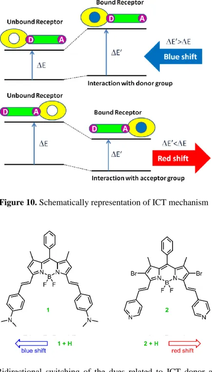
If the receptor unit, which is in conjugation with the fluorophore, is an electron donating group such as amino group, its interaction with a cation decreases its electron donating capability. This reduces conjugation and a blue shift is monitored in the absorption spectrum. That photophysical change occurring with the cation binding can also be explained by charge dipole interactions: The electron donating group will be positively charged in the excited state and its interaction with the cation will destabilize the excited state more than the ground state. Hence, an increase in the energy gap between ground and excited states will cause a blue shift in the absorption and emission spectra (Figure 10).
If the receptor unit is an electron accepting group such as carbonyl group, the interaction with a cation increases the electron withdrawing character of the receptor. When the acceptor group is in interaction with the cation, the excited state will be stabilized more than the ground state. As a result, the energy gap between the ground
13
state and the excited state will decrease in the presence of the cation and red-shift will be monitored in the absorption and emission spectra (Figure 10).
Figure 10. Schematically representation of ICT mechanism
Figure 11. Bidirectional switching of the dyes related to ICT donor and acceptor
14
Depending on the receptor moiety, similar compounds can display different spectral shifts upon the binding of the same analyte. For instance, two bodipy dyes showing similar spectral properties (Figure 11) exhibits opposite spectral shifts upon protonation82. One of the dyes includes electron donating aniline moiety whereas the other one contains electron accepting pyridine moiety as receptor units. Consequently, those two compounds demonstrate spectral shifts in the opposite directions in their proton bound form, due to the reasons explained above.
1.3.4 Energy Transfer
Energy transfer (ET) is another signaling event, which is used to modify fluorescence characteristics of a chromophore. It is the process where the energy of one chromophore (energy donor) at its excited state is transferred to other chromophore (energy acceptor) in bi(multi)chromophoric dye systems83. Hence, excitation energy of donor (D) is used to excite the acceptor through energy transfer.
Energy transfer occurs from the donor unit that absorbs at a relatively short wavelength to the acceptor unit that absorbs at a longer wavelength. Energy transfer characterization can be done following various parameters such as relative lifetimes, quantum yields, and decrease in donor emission & increase in acceptor emission. It is also influenced from the rate of deactivation pathways of excited system and thus chromophores must be appropriate to compete with those pathways83-84. Besides, excited state lifetime of donor has to be longer than the time required for energy transfer.
Energy transfer occurs by two different types of mechanisms: Förster type (through space) and Dexter type (through bond) (Figure 12).
15
Figure 12. Förster type (through space) and Dexter type (through bond) energy transfer
1.3.4.1 Förster Type Energy Transfer
In Förster resonance energy transfer (FRET), donor and acceptor moieties are usually connected via a non-conjugated linker. FRET does not depend on orbital interaction between donor and acceptor units and hence a large distance between donor and acceptor groups would still allow this type of energy transfer to occur. Spectral overlap between donor emission and acceptor absorption, the distance between donor and acceptor and relative orientation of their transition dipoles are especially important parameters for FRET85-87. They determine the chance of energy transfer to occur in the first place and its rate and efficiency afterwards.
In the mechanism of FRET, an electron in HOMO of the acceptor is excited to its LUMO through the energy released during the relaxation of an electron in the LUMO
16
of the donor to its HOMO. The energy absorbed by the acceptor unit matches the emission wavelength of the donor (spectral overlap).
FRET efficiency is determined using two different approaches; one is steady state approach and the other one is time-resolved approach88. Decrease in quantum yield of donor is followed in steady state approach. In this method, inner filter effect, which refers to re-absorption of the emitted light by the same molecule, is an important problem that should be avoided. This problem might be solved by the use of very dilute solutions89-90. FRET efficiency with steady state approach is formulated as:
E = 1 – (
DA
D)where
DA and
D are quantum yields of donor in the presence and the absence ofacceptor, respectively. It can also be calculated with a different formula, which is based on the increase in the fluorescence of acceptor:
E = AA (
D) / AD (
D) * [IAD(
A em) / IA(
A em) - 1]
where AA and AD refer to absorbance values of acceptor and donor at the maximum
absorbance wavelength of donor. IAD and IA refer to integrated emission area of
acceptor in the presence and absence of donor at Aemrespectively.
Time resolved approach enables a more accurate FRET efficiency calculation, which is determined using time-resolved emission of donor and acceptor. When the decay of emission is a single exponential, FRET efficiency can be formulated as follows88:
E =
D*kFRET / (1 +
D*kFRET)k
FRET= 1/
DA- 1/
Dwhere
D and
DA refer to excited state decay time (lifetime) of donor in the absence17
Figure 13. A Bodipy based Förster type energy transfer system
In Förster type energy transfer systems, Bodipy dyes are widely used. One of them91 is shown in Figure 13: four Bodipy units and a perylene diimide core are “clicked” together with “Huisgen cycloaddition”. The extinction coefficient of the dye at Bodipy’s maximum absorption wavelength (526 nm) dramatically goes up to 250000 M-1cm-1 due to four Bodipy structures in the dye. The emission of the core enhances, as expected, with the increasing number of terminal Bodipy donors. FRET efficiency is calculated as 99% with a critical Förster radius of 4.7 nm91.
1.3.4.2 Dexter Type Energy Transfer
Dexter type energy transfer, on the contrary to the Förster type, depends on the orbital interaction of donor and acceptor moieties92. It usually happens in the systems where donor and acceptor units are connected by a conjugated linker. In this kind of energy transfer, an exchange of electrons occurs between both HOMOs and LUMOs of donor and acceptor (Figure 12). The dependency of Dexter type energy transfer on orbital interaction limits energy transfer to short distances, generally less than 10 Å84. Hence, rate constant of energy transfer exponentially decreases with increasing distance between donor and acceptor:
18
where K represents orbital interaction, J is the overlap integral between donor emission and acceptor absorbance, RDA is the donor acceptor separation and L is the
van der Waals radii84.
In anthracene-Bodipy system in Figure 14, a very fast energy transfer (~200 fs) is observed from anthracene to Bodipy when anthracene is excited, that occurs as a result of parallel alignment of S1 - So transition dipole moments of donor and acceptor
respectively93-94. Another example of Dexter type energy transfer is displayed in Figure 15: Such ligand-metal based systems provide unidirectional energy transfer in a linear array of system that would be used in molecular wires95.In this example, an efficient energy transfer occurs from Ru and Os complexes to anthracene.
Figure 14. Anthracene-Bodipy based Dexter type energy transfer system
Figure 15. Ligand-metal based Dexter type energy transfer system
1.4
Higher Functions with Molecular Logic
Fundamental logic gates can carry out only basic logic operations, however, practical application of any digital device requires more complex logic systems including
19
arithmetic operations, complex functions performed on large data sets and so forth. These more complex logic systems performing higher level functions are usually formed by the integration of a couple of simple logic gates. And so far, a large number of molecular systems mimicking those higher functions5 such as half adder/subtractor, full adder/subtractor, encoder/decoder, multiplexer/demultiplexer and sequential logic have been reported in the literature.
1.4.1 Half Adder/Subtractor
Half-adder is a circuit that adds two one-bit binary numbers and yields two-bits. It composes of AND and XOR gates working in parallel6: it has two inputs and two outputs (Sum and Carry) (Figure 16).
Figure 16. Half-adder logic diagram with truth table
The first molecular half adder96 was demonstrated by de Silva et. al. in 2000. The system in that work is based on two different molecules with quinoline moiety mixed in one solution. Both molecules operate at the same time with the same chemical inputs. One (Figure 17a) operates as XOR gate in transmittance mode (at 390 nm) while another one (Figure 17b) operates as an AND gate in fluorescence mode by the Ca2+ and H+ chemical inputs (Figure 17).
Inputs Outputs A B Sum Carry 0 0 0 0 0 1 1 0 1 0 1 0 1 1 0 1
20
Figure 17. First molecular half adder
This molecular half adder96 corresponds to the electronic equivalents: both molecular gates use the same inputs and the outputs are independent of each other. Hence, XOR and AND molecular logic gates operated in parallel make a binary addition. After this study, lots of molecular half adder systems5, 97-108 have been developed and published. The first unimolecular binary half adder99 system was reported by Shanzer et. al. in 2005. This half adder is based on a plain fluorescein dye. Depending on pH, fluorescein molecule has four different ionization states (Figure 18) and each exhibits a unique absorption spectrum. Simply by monitoring absorption at different wavelengths, various gate behaviors can be obtained. In the study, an XOR gate is
21
achieved by monitoring absorption at 447 nm whereas an AND gate is attained at 501 nm (Figure 19).
Figure 18. Different ionization states of fluorescein upon protonation/deprotonation
22
Half-subtractor carries out a reverse operation of half adder: subtraction of two bits. Similarly, it has two inputs and two outputs (Difference and Borrow), and composes of XOR and INH gates6. Molecular implementation of half subtractor is more difficult than half adder.
Figure 20. Half subtractor logic diagram with truth table
First one109 of molecular half-subtractor examples5, 97, 99, 102, 110-116 was reported in 2003 by Langford and Yann. In the study, the operation of the molecular device relies on red shift in the absorption band of tetraphenylporphyrin and the change in the emission intensity upon protonation/deprotonation. The absorption band of tetraphenylporphyrin (H2TPP) is localized at 417 nm. It shifts to 440 nm on
protonation (H4TPP2+) and 430 nm on deprotonation (TPP2-) (Figure 21). Besides,
only protonated and deprotonated forms of tetraphenylporphyrin exhibit a strong emission: H4TPP2+ shows a strong emission at 405 nm while TPP2- emits at 440 nm.
When either acid or base is present in the media, a strong absorption at > 425 nm is monitored and this part corresponds to XOR gate. On the other hand, a strong emission is observed at the wavelengths of 405 or 440 nm only in the presence of one of the inputs (acid or base) and this part corresponds to INHIBIT gate. Coupling of XOR and INH gates in one molecule (tetraphenylporphyrin) using the same inputs and yielding different outputs (Figure 20) produces a molecular scale binary half subtractor. Inputs Outputs A B Diff Borrow 0 0 0 0 0 1 1 1 1 0 1 0 1 1 0 0
23
Figure 21. The first molecular half subtractor based on tetraphenylporphyrin109
1.4.2 Full Adder/Subtractor
Full adder is more complex one that composes two half adders and one OR gate and yields two-bits upon full addition of three one-bit numbers (Figure 22). In a similar fashion, full subtractor performs the subtraction of three one-bit numbers producing two-bits6. Arithmetic operations at highest complexity are accomplished in binary full adders and full subtractors.
24
Full Adder Full Subtractor
Inputs Outputs Inputs Outputs
A B Cin S Cout A B Bin D Bout 0 0 0 0 0 0 0 0 0 0 0 0 1 1 0 0 0 1 1 1 0 1 0 1 0 0 1 0 1 1 0 1 1 0 1 0 1 1 0 1 1 0 0 1 0 1 0 0 1 0 1 0 1 0 1 1 0 1 0 0 1 1 0 0 1 1 1 0 0 0 1 1 1 1 1 1 1 1 1 1
Table 2. Truth tables for full adder and full subtractor
The first molecular system combining full adder and subtractor in the same molecule was demonstrated by D. Margulies et. al. in 2006117. The molecular full adder/subtractor in the work relies on a simple fluorescein molecule. Acid and base are used as inputs, and changes in absorbance, transmittance and emission are monitored as outputs. Protonation/deprotonation of fluorescein leads to changes in its absorption spectrum (Figure 23). In the work, 447 nm is chosen as the characteristic wavelength in the absorption spectrum for monocationic and monoanionic state of fluorescein while 474 nm is selected for monoanion and dianion form. The neutral form displays a weak absorption at both 447 and 474 nm.
25
When the transmittance at 447 nm is selected as the sum output and absorption at 474 nm is appointed as the carry output, a full adder is accomplished. This fluorescein based full adder works starting from the monocationic form; it corresponds to [0,0,0] set of inputs (each input is OH- ion) and it results sum=0 (low transmittance at 447 nm) and carry=0 (low absorbance at 474 nm). When one equivalent OH- ion is added, produced neutral form exhibits high transmittance at 447 nm (sum=1) and low absorbance at 474 nm (carry=0). Addition of two equivalents of OH- ion yields monoanionic form of fluorescein, which shows low transmittance at 447 nm (sum=0) and high absorption at 474 nm (carry=1). In the case of three equivalent of OH -addition, dianion forms and it has a high transmittance at 447 nm and a high absorbance at 474 nm. In this case, both sum and carry is 1 (Figure 24).
Figure 24. A full adder based on fluorescein molecule
A full subtractor is achieved with the same system as well: In this instance, absorbances at 447 nm and 474 nm are used as outputs whereas both acid and base are used as chemical inputs. Operation of this fluorescein based full subtractor begins with the neutral form; it corresponds to [0,0,0] set of inputs (Figure 25).
26
Figure 25. A full subtractor based on fluorescein molecule
The acid input is set as the minuend while base input is assigned to both the subtrahend and Bin. The full subtractor, which is based on the half subtractor, also
performs two-bits subtraction in the absence of additional Bin input so lines “a-d” in
the truth table are naturally obtained (Figure 25). Furthermore, the set of chemical inputs in lines “d” and “g” produces the identical output signals (0,0) with the line “a” because of mutual destruction of acid and base. In a similar way, set of inputs in lines “e” and “h” must give the same output signals (1,1) with the one in line “b”. Only the set of inputs expressed in line “f” gives rise to a new chemical environment (di-anionic form) that has no corresponding analogy in the molecular half subtractor and it results the correct output signals (1,0) (Figure 25). As a consequence, this system results in a complete molecular full subtractor device.
1.4.3 Multiplexer/Demultiplexer
Molecular logic systems can also perform non-arithmetic functions such as multiplexer and demultiplexer. A multiplexer is a circuit analogous to a switch that combines various inputs into an output (a single signal). Once several input signals are multiplexed into one output, they can be separated again using a demultiplexer. This allows the combination of multiple signals in the multiplexer, transmission on a
27
single data line and then individual recovery again in the demultiplexer at the other end of the line118.
There are a few numbers of molecular multiplexers/demultiplexers118-120 reported in the literature. One has been lately published in by Andreasson and coworkers121. In that work, they report a unimolecular photochromic triad (FG-DTE) that performs as 2:1 multiplexer and 1:2 demultiplexer (Figure 26). The molecule consists of dithienylethene (DTE) and two fulgimides (FG) and it photoisomerizes between open and closed forms using lights at different wavelengths (Figure 26). The isomers are FGo-DTEo, FGc-DTEo, FGo-DTEc, and FGc-DTEc and each shows a unique absorption and emission spectrum121.
FG-DTE molecule functions as a 2:1 multiplexer. It has two data inputs - 397 nm light and red light (>615 nm). A third input is the selector input (366 nm light), which is applied to the FGo-DTEo (initial state) before data inputs and decides which
data input’s state will be transmitted to the output, which is the emitted light at 624 nm. When the third input is off, the state of first input is directly transferred to the output while the state of second input is ignored. However, the output reports the state of second input and ignores the first input when the third input is on121 (Figure 27).
FG-DTE molecule also functions as a 1:2 demultiplexer that reverses the effect of the 2:1 multiplexer. In this case, 1:2 demultiplexer has such a data input that the output from multiplexer serves as the data input for the demultiplexer121. The data bits are now disentangled in the demultiplexer to either output 1 (O1) or output 2 (O2), which depends on the second input’s state (the address input – Ad) (Figure 28).
28
29
Figure 27. Performance of FG-DTE as 2:1 multiplexer121
30
1.4.4 Encoder/Decoder
An encoder is a device that compresses digital information for transmission or storage and converts information into a code while compressing it. For example, a single bit 4-to-2 encoder converts 4 bits of data to 2 bits. Each one of four different inputs (I0
-I3) takes values of either 0 or 1 that produces 0 or 1 binary values for two outputs (O0
= sum digit, O1 = carry digit). On the contrary, a decoder converts the compressed
information back into the initial form. In a similar way, a 2-to-4 decoder converts 2 bits of information back to 4 bits using two inputs and producing 4 outputs122.
The above mentioned photochromic triad (FG-DTE) (Figure 26) that performs the function of multiplexer/demultiplexer also performs as a single bit 4-to-2 encoder and 2-to-4 decoder121-123. Briefly, all of the 4 inputs for the encoder are photonic: light at 460, 397, 302 and 366 nm. The outputs are absorptions at 393 and 535 nm. In the case of decoder, the inputs are the light at 397 and 302 nm while the outputs are absorptions at 393 and 535 nm, transmittance at 535 nm and emission at 624 nm. The initial form of the molecule for both encoder and decoder is FGo-DTEo.
In0 In1 In2 In3 Out1 Out0
1 0 0 0 0 0
0 1 0 0 0 1
0 0 1 0 1 0
0 0 0 1 1 1
Table 3. Truth table for the 4-to-2 encoder
In1 In0 Out0 Out1 Out2 Out3
0 0 1 0 0 0
0 1 0 1 0 0
1 0 0 0 1 0
1 1 0 0 0 1
31
Another molecular encoder/decoder work uses a well-known [Ru(bpy)3]2+
(bpy=2,2’-bipyridine) metal complex124. The complex performs as an encoder/decoder with a set of electronic and photonic inputs/outputs in this instance.
Figure 29. The 4-to-2 encoder based on [Ru(bpy)3]2+ metal complex
32
1.4.5 Sequential Logic
The output of the combinatorial circuits such as half adder/subtractor, multiplexer and encoder is exclusively a function of current inputs, meaning that history of inputs has no effect on device function. However, the output of the sequential circuits is determined by the current state of the system that involves both previous and present inputs. Since such a circuit remembers information about the previous input, it functions as a memory element. Hence, this feature requires the use of feedback loops that connect the output of a logic gate back to one of its inputs. Sequential logic systems are used in memory devices and storage elements125-129.
Figure 31. General representation for sequential logic circuit
Recently van der Boom group have progressed in the area of molecular sequential logic, including the molecular random-access memory (RAM). Their work relies on surface-immobilized Os2+ polypyridyl complex (Figure 32) that behaves as a logically active monolayer125. The redox active Os (2+, 3+) center is treated with oxidizing and reducing type input reagents. The output is taken as a change in the absorption spectrum by the conversion of Os2+ to Os3+ and vice versa.
33
Figure 32. The osmium polypyridyl complex used in the study
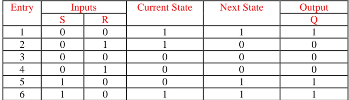
Using this versatile platform (Figure 32), sequential logic devices such as S-R latch have been implemented. In S-R latch, two cross-coupled NOR gates are integrated (Figure 33). Q=1 corresponds to high absorption at 496 nm (Os2+ oxidation state) while Q=0 is defined as low absorption at the same wavelength corresponding to Os3+ complex. The inputs are appointed as Co2+ and Cr6+ (pH<1) for the Set (S) and Reset (R), respectively. Whenever S=1 (Set input is high), the system writes and memorizes the binary state “1”. When R=1 (Reset input is high), the binary state “1” is erased. Rather, the binary state “0” is written and memorized125
. Table for this Os2+ polypyridyl based monolayer performing an S-R latch with two chemical inputs (S=Co2+ and R=Cr6+) is as follows (Table 5):
Entry Inputs Current State Next State Output
S R Q 1 0 0 1 1 1 2 0 1 1 0 0 3 0 0 0 0 0 4 0 1 0 0 0 5 1 0 0 1 1 6 1 0 1 1 1
34
Figure 33. Schematic representation of SR latch
In the following set of experiments, they also performed combinatorial and sequential logic with the same system. A distinct oxidation state of the metal before each entry produces combinatorial logic while the dynamic state results in a sequential logic. A third input (Ir3+) is introduced this time to mimic the features of both circuits125. Another system that operates as an SR latch was also demonstrated by Willner, Tian and coworkers127. They reported an electrochemically active DTE photochrome assembled on a gold electrode (Figure 34) and the system is based on the electrocyclization of the DTEo to DTEc (Reset input: E=0.35 V) and photochemical
back isomerization of DTEc to DTEo (Set input: light at 570 nm). The Q state is
monitored as the fast scan cyclic voltammetric response of the DTE, which differs for its open and closed forms.
35
1.4.6 Functional Integration
So far, more complex logical systems operating higher functions such as half adder/subtractor, full adder/subtractor, multiplexer/demultiplexer, encoder/decoder and sequential logic have been mentioned. It is known that these higher functions require a considerable degree of integration between logic gates. And, until now, almost all of the integration or concatenation between molecular logic gates is “functional”, meaning that the outputs at several channels such as at different wavelengths are determined and then an integrated set of logic gates is suggested to be performing on inputs to produce the outputs. In other words, one molecule or a molecular assembly represents the entire logic circuit rather than a logic gate. This type of integration or concatenation can also be called “virtual”.
This approach is convenient and can be useful in silicon technology; however, it is clear at some point that physical integration of molecular (chemical) logic gates must be of great importance for the rational design and implementation for advanced molecular computing. Physical integration of chemical logic gates is unfortunately difficult because of inhomogeneity between the nature of inputs and outputs, such as chemical inputs and optical outputs. Nevertheless, there still has to be some simple methods to integrate independently working chemical logic gates in a physical way such that the output of one gate must be the input of the other gate.
36
CHAPTER 2
EXPERIMENTAL
2.1 Methods and Materials
1H NMR and 13C NMR spectra were recorded in CDCl3 on Bruker DPX-400
(operating at 400 MHz for 1H NMR and 100 MHz for 13C NMR) with tetramethylsilane as internal standard. All spectra were taken at 25 oC and coupling constants (J values) were given in Hz. Chemical shifts were given in parts per million (ppm). Splitting patterns were indicated as s (singlet), d (doublet), t (triplet), q (quartet), p (pentet) and m (multiplet). All the 13C spectra were recorded with simultaneous decoupling of proton nuclei.
Mass spectra were obtained on Agilent Technologies 6530 Accurate-Mass Q-TOF LC/MS. Absorption spectra were taken by using a Varian Cary-100 spectrophotometer. Fluorescence measurements were performed on a Varian Eclipse spectrofluorometer. Fluorescence life-time measurements were carried out on a HORIBA Jobin Yvon fluorolog (FL-1057). HORIBA Scientific NanoLEDs at 560 nm, 590 nm, 605 nm, 650 nm and 667 nm (pulse width < 250ps) were used for the life-time measurements. The instrument response function was measured with an aqueous Ludox solution. The decays were analyzed with a multi-exponential fitting function by iterative reconvolution and chi-square minimization. The white light used in the reduction of thionine dye was KENGO LIGHTING (F118WH); its voltage and maximum wattage was 230 V – 50 Hz and 500 W, respectively.
Reactions were monitored by thin layer chromatography using Merck TLC Silica gel 60 F254. Silica gel column chromatography was performed over Merck Silica gel 60
(particle size: 0.040-0.063 mm, 230-400 mesh ASTM). All other reagents and solvents were purchased from Aldrich and used without further purification.
4-(1,4-37
dioxa-7,13–dithia–10 azacyclopentadecan–10-yl) benzaldehyde130 was synthesized according to literature.
2.2 Synthesis of Target Molecule 1 (Compound 4)
2.2.1 Synthesis of Compound 1
Figure 35. Synthesis of Compound 1
500 micro liter of aniline, 1.75 g of 2-(chloro methyl) pyridine, 3 g of potassium carbonate were mixed in 100 ml of acetonitrile in a round bottomed flask. Some amount of KI and 18-crown-6 were added as catalysts and the mixture was allowed to stand for 3 days for a complete reaction. Then, the reaction mixture was washed with water (3 x 300 ml) and dried over anhydrous Na2SO4. The solvent was evaporated
and the residue was purified by silica gel column chromatography using Acetone-Hexane (1:1) solution. Finally, the desired brown solid (1.45 g, 76%) was obtained.
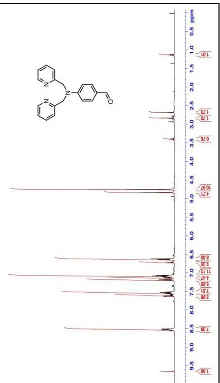
1 H NMR (400 MHz, CDCl3): δH 8.60 (2H, d, J = 4.21 Hz), 7.62 (2H, t, J = 16.35 Hz), 7.27 (2H, d, J = 8.14 Hz), 7.17 (4H, m, J = 12.04 Hz), 6.71 (3H, m, J = 20.12 Hz), 4.83 (4H, s) ppm. 13 C NMR (100 MHz, CDCl3): C 158.9, 149.8, 148.2, 136.9, 129.4, 122.1, 120.9, 117.3, 112.6, 57.4 ppm.
38
2.2.2 Synthesis of Compound 2
Figure 36. Synthesis of Compound 2
To a cooled (0°C) solution of anhydrous DMF (10mL), POCl3 (4 mmol, 0.615 g) was
added within 5 min. The mixture was stirred for 30 min at room temperature and then Compound 1 (3.4 mmol, 1 g) was added. The resulting mixture was heated for 5 hours at 80°C. The dark brown solution was slowly added to cold water and then neutralized with K2CO3. The product was extracted with CH2Cl2 and dried over
anhydrous Na2SO4. The solvent was evaporated and the residue was purified by silica
gel column chromatography using Acetone-Hexane (1:1) solution as the eluent. Yellowish brown solid (0.7 g, 64%) was obtained.
1 H NMR (400 MHz, CDCl3): H 9.71 (1H, s), 8.61 (2H, d, J = 4.15 Hz), 7.66 (4H, m, J = 24.03 Hz), 7.21 (4H, m, J =16.21 Hz), 6.80 (2H, d, J = 8.80), 4.92 (4H, s) ppm. 13 C NMR (100 MHz, CDCl3): C 190.2, 157.2, 153.1, 149.9, 137.0, 132.1, 126.4, 122.5, 120.7, 112.0, 57.1 ppm.
39
2.2.3 Synthesis of Compound 3
Figure 37. Synthesis of Compound 3
2,4-dimethyl pyrrole (6.6 mmol, 0.6 g), 4-(N,N-di-(pyridine-2-ylmethyl)amino) benzaldehyde(compound 2) (2.97 mmol, 0.9 g) and one drop of trifluoroacetic acid were added to a 1.0 L round-bottomed flask containing 600 ml argon-degassed CH2Cl2. The solution was stirred under N2 (g) at room temperature for 1 day. After
addition of a solution of DDQ (2.97 mmol, 0.67 g) in 150 ml CH2Cl2 to the reaction
mixture, stirring was continued for 30 minutes. Then, 9 ml of Et3N and 8 ml of
BF3.OEt2 were successively added. After 30 minutes, the reaction mixture was
washed with water (3 x 300 ml) and dried over anhydrous Na2SO4. The solvent was
evaporated and the residue was purified by silica gel column chromatography using Chloroform-Methanol (97:3) solution as the eluent. Orange solid (0.38 g, 23%) was obtained.
1
H NMR (400 MHz, CDCl3): H 8.60 (2H, d, J = 6.48 Hz, ArH), 7.62 (2H, t, J = 7.71
Hz, ArH), 7.22 (2H, d, J = 7.84 Hz, ArH), 7.18 (2H, t, J = 6.58 Hz, ArH), 6.98 (2H, d, J = 8.80, ArH), 6.80 (2H, d, J = 8.80, ArH), 5.95 (2H, s, ArH), 4.87 (4H, s, CH2),
40
13
C NMR (100 MHz, CDCl3): C 158.3, 154.8, 149.8, 149.7, 148.8, 143.1, 136.7,
128.9, 123.3, 122.2, 120.9, 113.2, 57.4, 14.5 ppm.
2.2.4 Synthesis of Compound 4
40 ml of benzene, compound 3 (0.15 mmol, 80 mg), 4-propargyloxy benzaldehyde (0.15 mmol, 24 mg), acetic acid (0.2 ml) and piperidine (0.2 ml) were added to a 100 ml round-bottomed flask equipped with a Dean-Stark trap and a reflux condenser. The reaction mixture was stirred at reflux temperature and then concentrated nearly to dryness. When all the starting material had been consumed, 100 ml water was added and the mixture was extracted into CHCl3. The organic layer was dried on Na2SO4
and evaporated. Column chromatographic separation (1:1 Hexane-Acetone solution) of the residue yielded the desired dark purplish-red solid product. (21 mg, 20%).
Figure 38. Synthesis of Compound 4
1
H NMR (400 MHz, CDCl3): H 8.62 (2H, d, J = 4.84 Hz, ArH), 7.65 (2H, t, J =
8.54 Hz, ArH), 7.60-7.54 (3H, m: 2H, ArH; 1H, CH), 7.26-7.15 (5H, m: 4H, ArH; 1H, CH), 7.03 (2H, d, J = 8.84 Hz, ArH), 6.98 (2H, d, J = 8.85 Hz, ArH), 6.80 (2H, d,
41
J = 8.84 Hz, ArH), 6.58 (1H, s, ArH), 5.90 (1H, s, ArH), 4.88 (4H, s, CH2), 4.74 (2H,
d, J = 2.44 Hz, OCH3), 2.58 (3H, s, CH3), 2.55 (1H, t, J = 2.46 Hz, CH), 1.48 (3H, s, CH3), 1.44 (3H, s, CH3) ppm. 13 C NMR (100 MHz, CDCl3): C 158.3, 154.5, 153.0, 149.8, 148.8, 142.5, 139.0, 136.7, 135.2, 130.4, 129.2, 128.8, 122.2, 120.9, 117.7, 117.1, 115.1, 113.2, 78.7, 75.8, 57.4, 55.9, 29.7, 14.8, 14.6 ppm.
MS (TOF - ESI): m/z: Calcd: 663.2981 [M+], Found: 664.30697 [M+H]+,
=1.3 ppm.2.3 Synthesis of Target Molecule 2 (Compound 10)
2.3.1 Synthesis of Compound 5
Figure 39. Synthesis of Compound 5
1,4-hydroxybenzaldehyde (5 g, 41 mmol) and 1,8 dibromohexane (2 g, 82 mmol) were dissolved in acetone (150 ml). K2CO3 (17.2 g, 123 mmol) and a few crystals of
18-crown-6 were added. The reaction mixture was refluxed for 12h. Then, acetone was evaporated and the mixture was extracted with water and chloroform. After drying organic layer with Na2SO4 and evaporation, the product was purified by silica
gel column chromatography using CHCl3-Hexane (3:1) solution. Fraction containing
compound 5 was collected then the solvent was removed under reduced pressure (6.7 mmol, 1.906 g, 16%).
42 1 H NMR (400 MHz, CDCl3): H 9.7 (1H, s), 7.68 (2H, d, J= 8.64 Hz), 6. 82 (2H, d, J= 8.76 Hz), 3.88 (2H, t, J= 6.4 Hz), 3.4 (2H, t, J= 6.68 Hz), 1.65 (4H, m), 1.35 (4H, m) ppm. 13 C NMR (100 MHz, CDCl3): C 190.58, 164.08, 131.86, 129.73, 114.68, 68.09, 44.91, 32.39, 28.83, 26.51, 25.4 ppm.
2.3.2 Synthesis of Compound 6
Figure 40. Synthesis of Compound 6
Compound 5 (1.089 g, 3.82 mmol) and 2,4-dimethyl 3-ethyl pyrrole (0.94 g, 7.7 mmol) were added to 300 ml argon-degassed CH2Cl2 in a round-bottomed flask. The
color of the solution turned into red after the addition of 3 drops of trifluoroacetic acid. The reaction mixture was stirred at room temperature for 12h. Then, tetrachloro-1,4-benzoquinone (0.93 g, 3.82 mmol) was added and the reaction mixture was stirred at room temperature for 45 min. Triethyl amine (8 ml) and boron trifluoride diethyl etherate (8 ml) were added sequentially. After stirring at room temperature for 30 min, it was extracted with water. Organic layer was dried with Na2SO4 and
evaporated under reduced pressure. The product was purified by silica gel column chromatography using CHCl3 as mobile phase. Fraction containing compound 6 was
43
collected and then the solvent was removed under reduced pressure (670 mg, 1.2 mmol, 31%). 1 H NMR (400 MHz, CDCl3): 7.15 (2H, d, J= 8.56 Hz), 7.0 (2H, d, J= 8.56 Hz), 4.05 (2H, t, J= 6.45 Hz), 3.59 (2H, t, J= 6.64 Hz), 2.55 (6H, s), 2.3 (4H, q, J= 7.56), 1.85 (4H, m), 1.58 (4H, m), 1.35 (6H, s), 1.0 (6H, t, J= 7.52) ppm. 13 C NMR (100 MHz, CDCl3): C 159.47, 153.46, 140.0, 138.43, 132.60, 130.10, 129.44, 127.78, 114.95, 67.87, 44.96, 32.48, 29.11, 26.67, 25.43, 17.06, 14.61, 12.46, 11.84 ppm.
2.3.3 Synthesis of Compound 7
Figure 41. Synthesis of Compound 7
Compound 6 (190 mg, 0.34 mmol) was dissolved in 20 ml DMSO. Then, excess amount of sodium azide (600 mg, 9.23 mmol) was added to the solution. The reaction mixture was stirred for 30 minutes at 60oC and then it was extracted with water and CHCl3 a few times to get rid of DMSO and excess NaN3. Organic layer containing
compound 7 was dried with Na2SO4 and evaporated under reduced pressure. No
44 1 H NMR (400 MHz, CDCl3): 7.15 (2H, d, J= 8.56 Hz), 7.0 (2H, d, J= 8.56 Hz), 4.05 (2H, t, J= 6.45 Hz), 3.32 (2H, t, J= 6.64 Hz), 2.55 (6H, s), 2.3 (4H, q, J= 7.56 Hz), 1.85 (2H, m), 1.68 (2H, m), 1.54 (4H, m), 1.35 (6H, s), 1.0 (6H, t, J= 7.52 Hz) ppm. 13 C NMR (100 MHz, CDCl3): C 159.46, 153.46, 140.33, 138.43, 132.61, 131.19, 127.77, 114.95, 67.86, 51.38, 29.13, 28.80, 26.56, 25.71, 17.07, 14.62, 12.46, 11.84 ppm.
MS (TOF - ESI): m/z: Calcd: 521.3137 [M+], Found: 520.3065 [M-H]+,
=1.6 ppm.2.3.4 Synthesis of Compound 8
Figure 42. Synthesis of Compound 8
40 mL of benzene, compound 7 (0.20 mmol, 0.106 g), 4-(1,4-dioxa-7,13-dithia-10-azacyclopentadecan-10-yl) benzaldehyde130 (0.20 mmol, 0.072 g), acetic acid (0.2 ml), and piperidine (0.2 ml) were added to a 100 ml round-bottomed flask equipped with a Dean-Stark trap and a reflux condenser. The reaction mixture was stirred at