Interaction-based Feature-Driven
Model-Transformations
for Generating E-Forms
Bedir Tekinerdo
ğ
an
Bilkent University Dept. of Computer Engineering
06800 Bilkent, Ankara, Turkey
[email protected]
Namik Aktekin
eMaxx B.V. Hengelo, P.O. Box 768,
7550 AT, Hengelo, The Netherlands
[email protected]
ABSTRACT
One of the basic pillars in Model-Driven Software Development (MDSD) is defined by model transformations and likewise several useful approaches have been proposed in this context. In parallel, domain modeling plays an essential role in MDSD to support the definition of concepts in the domain, and support the model transformation process. In this paper, we will discuss the results of an e-government project for the generation of e-forms from feature models. Very often existing model transformation practices seem to largely adopt a closed world assumption whereby the transformation definitions of models are defined beforehand and interaction with the user at run-time is largely omitted. Our study shows the need for a more interactive approach in model transformations in which e-forms are generated after interaction with the end-user. To show the case we illustrate three different approaches for generation in increasing complexity: (1) offline model transformation without interaction (2) model transformation with initial interaction (3) model-transformation with run-time interaction.
Categories and Subject Descriptors
D.2.2 [Software Engineering]: Design Tools and Techniques.
General Terms
Design, Documentation, Performance, Verification
Keywords
Model-driven software development, Feature-oriented modeling, e-government
1.
INTRODUCTION
One of the basic pillars in Model-Driven Development is defined by model transformations and likewise several useful approaches have been proposed in this context [6][1]. In addition it should be noted that the goals of model-driven development also depend on the identification and modeling of the right domain concepts. As such domain analysis plays an essential role in MDSD to support the definition of concepts in the domain. Domain analysis is a systematic approach for analyzing and modeling the domain concepts that are relevant for the stakeholders [2]. One of the common techniques for domain modeling is feature modeling, which has been extensively used in domain engineering [2]. Hereby, a feature model is a result of a domain analysis process in which the common and variant properties of a domain are elicited and modeled. In addition, the feature model identifies the constraints on the legal combinations of features. A feature model can thus be considered as a specification of the family.
In this paper, we report on our experiences of applying feature modeling to model-driven development. The context of the case is an e-government project which aims to use information and communication technology to provide and improve government services. E-government includes different models including government-to-government and government-to-citizen. We have focused on the model of local government-to-citizen which aims to support the interaction between local and central government and private individuals. Part of the e-government solutions are the generation of e-forms (electronic forms) for local governments. An e-form is the electronic version of its corresponding paper form. We have applied model-driven engineering techniques for the automatic generation of e-forms (electronic forms) from feature models.
This project has shown that feature modeling is an effective means not only to model the domain of e-forms but also to support the automatic generation in a model-driven engineering process. Besides of this observation the results of our study also presents an additional insight and lessons learned regarding model transformation practices in general. In particular it appeared that for defining e-forms offline static single generation is less suitable. This is because the specific e-forms depend on the user input and the retrieved data from the data administration services. In this paper we show three different approaches for generation with increasing complexity: (1) off line model transformation
Permission to make digital or hard copies of all or part of this work for personal or classroom use is granted without fee provided that copies are not made or distributed for profit or commercial advantage and that copies bear this notice and the full citation on the first page. To copy otherwise, or republish, to post on servers or to redistribute to lists, requires prior specific permission and/or a fee. FOSD'09, October 6, 2009 Denver, Colorado, USA Copyright © 2009 ACM 978-1-60558-567-3/09/10... $10.00
without interaction (2) model transformation with initial interaction (3) model transformation with run-time interaction. We report on our experiences and lessons learned and propose a systematic approach for defining model transformations that is based on an interactive paradigm.
The outline of the paper is structured as follows: In section 2 we provide the case study on e-form generators for local governments. In section 3 we show the automatic transformation process for generating e-forms from feature models. In section 4 we present an interaction-based model transformation. Finally section 5 presents the conclusions.
2.
CASE STUDY – E-FORM GENERATION
2.1
Description
The research has been carried out together with eMAXX which is a medium-size ICT company in Enschede, The Netherlands [5]. One of the objectives of eMAXX is to produce solutions for e-government (electronic e-government). Figure 1 shows an example interface of e-government gateway of the city Enschede, which the citizens can access to request services.
Figure 1. Example interface of a local government interface for
supporting e-services
An e-form is simply the electronic version of its corresponding paper form. E-forms have some benefits over paper forms including eliminating the cost of printing, storing, and distributing pre-printed forms. In addition e-forms can be filled out faster because the programming associated with them can automatically format, calculate, look up, and validate information for the user. With digital signatures and routing via e-mail, approval cycle times can be significantly reduced. Compared to paper forms, e-forms allow more focus on the business process or underlying problem for which they are designed (for example, expense reporting, purchasing, or time reporting). They can understand the roles and responsibilities of the different participants of the process and, in turn, automate routing and much of the decision making necessary to process the form.
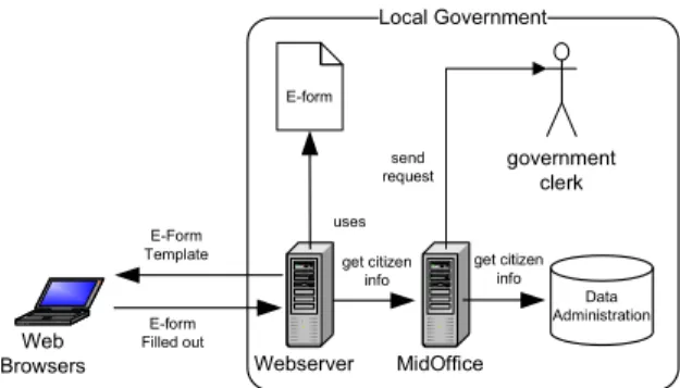
Using e-forms on the internet site of the local governments, citizens can perform requests such as making an appointment, informing about a movement, requesting a build license, etc. These services are defined on e-forms that are implemented by eMAXX. The deployment view is depicted in Figure 2.
Local Government E-form government clerk Web Browsers Webserver E-Form Template E-form Filled out get citizen info MidOffice Data Administration get citizen info uses send request
Figure 2. E-form generation –manual case
E-forms remain at a web server of a local government. Citizens can access these web pages through the internet browsers. E-forms are usually defined over multiple web pages. Once a user logs in to the system the user can select a number of services offered by the local government, such as for example notification
of movement. A middleware layer, defined by the MidOffice
server includes functions to access personal data of the registered users in the local government, which is stored in one or more back office systems, Data Administration. Based on the selected product and the user, the information about the user is requested from the common administration through MidOffice. The unknown fields are filled out by the user. After the citizen enters the last field the system needs to generate a report and submit the request to the government clerk. An important advantage of the
MidOffice is the loose coupling between the interfaces
(presentation) and the back offices (data). Different back office system can be accessed by different web browsers. The communication of the client web pages only communicate through the MidOffice which is responsible for the communication and distribution logic.
2.2
Problem Statement
In the initial version of the system, e-forms were manually implemented and deployed on the webserver of local governments. Moreover, e-forms are statically defined without taking into account the interaction with the user. A number of problems with this manual, static development solution can be identified.
• Lack of reuse of e-forms
First of all, even when we are dealing with the same kind of service, such as notification of movement, different local governments might require different kind of e-forms. The differences might be in the required type of data, the presentation form or the control flow i.e. the order in which the data is presented to the citizen. Although the e-forms share much commonality, the lack of systematic variability management requires that for each different local government an e-form needs to be implemented from scratch.
• Maintenance of e-forms
Even after deployment of the e-forms on the web servers, based on earlier practical experiences, updates might required to the implemented e-forms in due time. Unfortunately, the maintenance of the web pages including the e-forms is not trivial and again requires changes to the requested data, the presentation form or the control flow.
• Need for run-time generation of e-forms
Since the generation of some fields can only be known when a particular citizen is filling out the form, the specific required e-form can actually only be known at run-time. Because of this limitation usually the complete e-form is provided to the user, which complicates the process of filling out the form by the citizen. The e-form would be easier if only the required information is presented at the right time.
• Need for interaction by user
Finally, related to the previous third issue, when filling out the e-form, interaction with the Data Administration might be required to retrieve data to speed up the process or to complete the e-form. Unfortunately, in the initial version the interaction is only defined in the beginning during the authentication step of the citizen. Regarding the above issues the manual implementation of e-forms with only weak interaction with citizen and/or back offices is to some extent doable but certainly not cost effective. To optimize the development, maintenance and usage of e-forms automated support is necessary. The main objective here is to increase the reuse and productivity while developing and maintaining e-forms. For this, two basic issues need to be addressed. First of all, a domain model is required for defining e-forms. This domain model should be easy to understand and to be developed. Secondly, based on the domain model the target artifacts, that is, e-forms need to be automatically generated. To address these issues we have defined three different types of generators in increasing complexity:
- Generator without interaction. This generator transforms a
feature model to an e-form in which all the required fields are presented to the end-user. The end-user needs to fill out all the requested data and the e-form can only be completed if all the information is entered. Once the e-form is complete a report is generated and the service request is submitted for handling.
- Generator with single, initial interaction. This generator is
similar to the previous generator but allows for initial interaction with the data administration server to retrieve the values for the fields that can already be defined in the e-form - Generator with multiple, run-time interaction. This generator
complements the second generator by allowing interaction with user and data administration during run-time. For this a number of functions of data administration can be invoked to speed up the e-form completion process. Because of the multiple options for invoking functions the generator defines the related workflow for optimizing the function calls. Obviously, explicitly addressing interaction in model transformations is here a key issue. Unfortunately, current model-driven development practices tend to adopt a more closed-view approach in which interaction is not explicitly addressed. Our experiences in this industrial context aim to show both the necessity for interaction in model-transformations and the role of feature modeling. In the following sections we elaborate on the above generators.
3.
FEATURE-BASED MODEL
TRANSFORMATION
To address the requirements in the previous section we (1) define feature models of local governments, and (2) use these to generate e-forms and reports. Feature models have thus a dual role of modeling the data and as an intermediate form of e-forms. In the following we will discuss the first generator process which automates the e-form generation process but does not include interaction. In section 3.1 we will first focus on feature modeling of the services, and in section 3.2 we will discuss how we adopt and integrate feature models in the model-transformation process.
3.1
Feature Modeling of Services
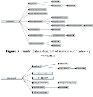
Different e-forms are implemented for different local governments but besides of the variations one can easily observe commonality of requested data. To model the domain for a given service we define a family feature model. Figure 3 shows, for example, a feature diagram for a service of a local government, which is the notification of moving. In fact this feature model defines the space of requested data that can be implemented on different e-forms. To put it differently, the feature diagram represents an intermediate representation for the space of e-forms. The feature model is already useful for supporting the implementation of e-forms. Different instantiations of the feature diagram indicate different definitions of e-forms. An example instantiation of the family feature diagram in Figure 3 is given in Figure 4.
Based on the application feature model the corresponding e-form can be implemented. Herewith, all the mandatory features will need to be mapped to fields. Optional and alternative features will be for example realized using check box fields, or radio buttons. We have defined a set of transformation rules and implemented these in the transformation definition. A possible corresponding e-form is depicted in Figure 5.
Figure 3. Family feature diagram of service notification of
movement
Figure 4. Application feature model of service notification of
Figure 5. Example E-form based on instantiated feature diagram
3.2
Model Transformations
In principle, feature models can be used for manually implementing e-forms. However, to support reuse and productivity, we will aim for automatic generation of e-forms. For this a generator needs to be defined that takes as input an instantiation of the feature model and provides as output the corresponding e-form. As defined in Figure 2, after the citizen fills out the e-form a report needs to be generated and the request should be handled. Obviously, here we can easily apply model-driven techniques to support the reuse and automation goals. For the given case, at least three different transformations are required as defined in Figure 6:
Defining feature model – The domain modeler defines a feature model of the required services. This is a manual process.
Application feature model to UI model – The instantiated feature model of the service, the application feature model, will be used to generate the UI model representing the e-form.
UI model to feature model – once the user fills out the required
fields in the form the UI model will be generated to the feature model.
Feature model to Report model – After all the fields in the
e-form are filled out, and the final feature model is generated, a report will be generated.
Figure 6. Required transformations for automatic e-form
generations
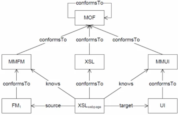
Figure 7 shows the transformation pattern for generating e-forms based on feature models. For defining the model transformation we need to define the source metamodel, the target metamodel and the transformation definition. In fact, both the source model and target models are known. The source model, FM1 in Figure 7, is a feature model, that conforms to a feature metamodel MMFM, which defines the common concepts for feature models. We have adopted the metamodel as defined in [3]. The target model UI defines e-forms, and conforms to a metamodel MMUI. All the models are represented using XML. The transformation applies XSLT which is a language for transforming XML documents to other XML documents. All the models in Figure 7 conform to the metametamodel MOF.
Figure 7. Transformation pattern for transforming feature model
to UI model (e-form)
Once the citizen has filled out all the fields the final instance of the feature diagram will be defined, requiring a transformation from UI model to feature model. This is in principle similar to the transformation pattern as shown in Figure 7, only the source model will now be the UI model and the model the feature model. Figure 8 shows the transformation pattern for generating reports based on e-forms. Since the e-form is represented as a feature model the source metamodel is a feature metamodel MMFM, and the target metamodel is a metamodel for describing reports, MMR.
Figure 8. Transformation pattern for transforming feature model
to Report
To sum up, this generation process automates the e-form development process by using feature models. The complete e-3
2 1 o
form is generated and presented to the citizen. Once the citizen has completed the e-form the report can be generated.
4.
MODEL TRANSFORMATION WITH
INTERACTION
In fact the overall model-driven process in section 3 largely supports the goals for automated development of e-forms. However, the transformation process in section 3 does not take into account interaction with the user and the data administration. The generated e-form is actually statically defined in one step, one web page is generated, and no interaction is possible with the end-user or data administration. In fact all the transformation steps in Figure 6 are executed once. In the following sections we will define generators that include interactions with the user and data administration.
4.1
Initial Interaction
The second more refined generator makes use of the calls to the data administration. After the authentication process and selection of a particular service the system can already retrieve some information about the citizen and the selected product and instantiate part of the feature diagram. As such, the time to fill out the form, as well as the chance for incomplete forms will be partially reduced.
Compared to the generation process of the previous section this generation process includes one more transformation pattern. This is the transformation from a source feature model to another target feature model. As such the process of e-form generation requires the following order of steps:
1. Authentication of user 2. Selecting product service 3. Loading family feature model
4. Call to data administration to retrieve personal details 5. Definition of application feature model based on retrieved
data in step 4
6. Generation of e-form based on application feature model 7. Entering data by user in the e-form of step 6
8. Transformation of e-form to feature model
4.2
Run-time Interaction
The first generator without interaction solves the automation problem of e-forms. By defining transformations e-forms can be automatically generated. The second generator allowed initial interaction with data administration to retrieve data that could be filled out. As such the e-form completion process time is reduced. However, both generators generate one complete web page in which all the fields are shown. Unfortunately, this is not always suitable since the generation of the specific fields in the e-form also depends on the data that is entered by the user, or the data is retrieved from the data administration, at run-time. As such, the third generator allows run-time interaction with the user and data administration. In this way, the e-form is generated incrementally dependent on the input of the end-user. This means that the instantiation of the family feature diagram is not done after authentication process but at any time during completing the e-form. Also multiple web pages including part of the e-form are generated.
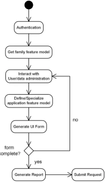
The interaction process is shown in Figure 9. After the authentication process, the family feature model is retrieved and the first fields are defined. Then follows a cycle of interaction with user and data administration in which the application feature model and likewise the corresponding e-form is specialized. Once the e-form is complete a report is generated and the request is submitted. In essence the transformation process is similar to the alternative without interaction. The main difference is that now the feature model is specialized multiple times and during the e-form completion process. Obviously, multiple model transformations are required to complete the process. In fact, this process also follows the idea of staged configuration of feature models as explained in [3].
Figure 9. Transformation pattern for transforming feature model
to UI model (e-form)
4.3
Optimizing Workflow
When interaction with the data administration is supported functions for data administration are accessed. Many different functions might be accessed given an application feature model. For example, the invocation of the function getPersonDetails can define the values for name, address, and id of the citizen. Further, each invocation of a function might result in the definition of the values of different fields.
In essence the aim is to optimize the e-form completion process and therefore the functions need to be preferably invoked in the order in which the maximum set of values in the e-form can be determined. The latter means that the number of fields that the citizen needs to enter is optimally reduced.
It appears thus that we need to address the workflow explicitly to optimize the generation process. In the first generator no data administration function was called at all. In the second generator only initial call was made to the data administration. As such the workflow concern was not considered in these two generators. In the third generator the workflow concern is explicitly considered by (1) defining the functions that can be invoked (2) defining the order in which they need to be processed. As such based on the state of the e-form (and the application feature model) a decision needs to be made which functions of the data administration need
to be called. Different strategies can be adopted for this. We have adopted a simple fixed, strategy which aims to optimize the number of model transformations needed. The workflow definition is defined as depicted in Figure 10.
Figure 10. Adopted workflow in the interaction-based e-form
generator
Hereby we first check whether mandatory features have been defined in the feature model. These are then first processed, that is an e-form is generated with these fields, and data input from the user is processed resulting in a new feature diagram. The following step is to select features that are related to functions in the data administration. The final step is the generation of optional features. Once all the fields have been entered the report is generated. In fact this is quite a simple workflow strategy and can be optimized in different ways. For example, we could prioritize the functions that result in more input from data administration; we could define the optimal path of these functions, etc. The full integration of strategy selection and optimization has been reserved for the future work.
5.
CONCLUSIONS
In this paper we have discussed our experiences with using feature models for generating e-forms using model driven engineering techniques. The basic conclusion of this work is that an appropriate domain model represented as feature diagrams provides a solid basis for the space of alternative target models. In our case the target models were basically e-forms. Using the conventional model transformation pattern we have defined four different kinds of model transformations: feature model to feature model, feature model to e-form, e-form to feature model, feature model to report. All these transformations supported the automation process of e-forms and as such improved reuse and productivity. In addition we have pinpointed the necessity for interaction in generating e-forms. This is because the e-form is not only defined by the selected service but also defined by the entered answers in the e-form or the retrieved information from the data administration. To cope with this issue, model transformations could not remain static and/or offline but had to be integrated in the run-time e-form completion process. Based on
the input at important steps in the e-form completion process the application feature model was regenerated and in accordance with this the e-form updated. It also appeared that hereby the order in which the functions of the data administration are accessed, i.e. the workflow, have an impact on the e-form completion process. In alignment with this issue, we have shortly discussed the notion of workflow concern. Our future work will focus on the interaction aspects in model transformations in general. We think that the lessons that we have derived from the considered project should be considered from a general and broader perspective. In particular the issue of interaction in the model-transformation process is a topic that needs further investigation.
ACKNOWLEDGMENTS
We would like to thank Mehmet Aksit, Anton Boerma and Richard Scholten for earlier support and discussions about this work.
REFERENCES
[1] J. Bézivin, F. Büttner, M. Gogolla, F. Jouault, I. Kurtev, A. Lindow. Model Transformations? Transformation Models!, MoDELS2006, Springer LNCS, Vol. 4199, pp. 440-452, 2006.
[2] K. Czarnecki and U. Eisenecker. Generative Programming:
Methods, Tools, and Applications, Addison Wesley, 2000.
[3] K. Czarnecki, S. Helsen and U. Eisenecker, Staged
Configuration Through Specialization and Multi-Level Configuration of Feature Models, Software Process
Improvement and Practice, special issue on Software Variability: Process and Management", vol. 10, pp. 143-169, 2005.
[4] Eclipse Modeling Framework Web Site, http://www.eclipse.org/emf/
[5] eMaxx B.V. Hengelo, P.O. Box 768, 7550 AT, Hengelo, The Netherlands. http://exxellence.nl/
[6] D.S. Frankel. Model-Driven Architecture, Wiley Publishing Inc., 2003.