2 (2), 2008, 315-328
©BEYKENT UNIVERSITY
A SIMULATION OF PHASE-SHIFTING
TRANSFORMER OPERATION IN STEADY
STATE AND EFFECT OF VOLTAGE DIP
Bora ALBOYACI
1, Elif INAN
2The University of Kocaeli, Faculty of Engineering Department of Electrical Engineering Kocaeli/TURKEY
e-mail: [email protected] 1
e-mail: [email protected] 2
Received: 18 December 2007, Accepted: 23 February 2008
ABSTRACT
As power systems get more complex and more stressed, appropriate tools to control the power flow within a given network are increasingly needed. Phase shifting transformers can serve as such tools. They can control power flow in a complex power network in a very efficient way. This paper presents how phase shifting transformers operate, how they are modeled in steady state operation, how they can control and affect of the voltage dip. It was shown that the fault distribution along those lines influences strongly characteristics of voltage dips at connection point. There simulation packages (SIMPOW, SIMPOW DIP and PSAT) are used to simulate phase shifting transformer's affects on the system.
Key Words: Phase-shifting transformers, Load Sharing, Voltage Dip.
ÖZET
Gün geçtikçe daha karmaşık hale gelen güç sistemlerinde güç akışı kontrolü için gerekli araçlara olan ihtiyaç da artmaktadır. Faz kaydıran transformatörler karmaşık bir güç sisteminde güç akışını verimli şekilde kontrol edebilmektedirler. Bu çalışma faz kaydıran transformatörlerin çalışma prensiplerini, kararlı hal durumu modellemesi ve gerilim azalmalarında oluşturduğu etkilediklerini değerlendirmektedir. Faz kaydıran transformatörlerinin etkisi basit bir test sistemi üzerinde (PSAT, SIMPOW DIP ve PSAT) simülasyon programları kullanılarak incelenmiştir.
1. INTRODUCTION
The phase-shifting transformers (PST), that's application field become larger, are used in complex electrical networks to control power flow. A PST forms a phase shift between its first and second winding (between source and load). Beside very special applications the aim of phase shift is to control power flow in transmission grid. To illustrate this, let us consider a simple system that carries total load from two parallel lines. Naturally, current is divided according to line impedances. If the line impedances have large difference, this current division will not be effective. By adding a voltage source to one of the line, the equivalent line current can be established [1-4].
When we consider two bus that has constant voltage and independent from load current, the power flow between two bus influences from bus voltages (V1, V2), phase shift (S ) and line impedance (X). This can be expressed by
equation (1).
V
P = ——— * sin S
(1)X
If a source, that gives a voltage with 90°, is placed between these two buses, a line current will occur that is in the same phase with line voltage and this increases active power flow. This state indicates the operation principle of a PST. Inserting a variable voltage between two windings, that its voltage is nearly perpendicular to line voltage, shifts phase angle. So power flow control in desired grid branch is established.
The voltage dip calculations are based on the so called "method of fault positions". With this method a number of fault positions are defined in the network. Each fault position represents faults in a small part of the network. Different fault types are applied at the fault positions one at the time and the remaining voltages at the customer locations in the network are calculated. The remaining voltages during faults are calculated using symmetrical component theory and corresponding network impedance matrices.
In this study, first of all operating principle and an equivalent circuit model of a PST is given. Effect of a PST in power control is shown with simulation studies. Under PST control, network voltage dip classification index changes are examined.
2. PST OPERATING PRINCIPLE AND MODELING
In conventional transformers, a variation in load current varies load side voltage tough in PST both voltage magnitude and phase angle changes. When a PST is used to increase power flow, phase angle between first and second
winding will be lower than the angle in no load and at the same tap position. Phase angle variation according to loading can be expressed as follows.
A a = arctan- ¡fkt * xf l t *c o sf f
1 + ijkt * f t *c o s^
(2) In this expression Aa defines angle variation according to load current, ifkt indicates PST current in pu, xfkt point out PST impedance in pu and 9 describe the angle between load voltage and load current. Low xfkt decrease this effect. If a comparison is made between one PST with low impedance but the same phase angle with the second PST, it can be seen that the lower the impedance the higher phase shift at same load. It can be also explained that if a determined phase angle is given, PST with lower impedance will decrease phase angle at no load. When a PST is used to decrease power flow, phase angle at rated load can be increased by the voltage drop on PST impedance. In this situation PST impedance increase PST efficiency. But this time PST voltage must be higher than loadless situation and this makes core over-excitation. In construction this situation must be considered. A PST with zero phase angle decrease power flow.
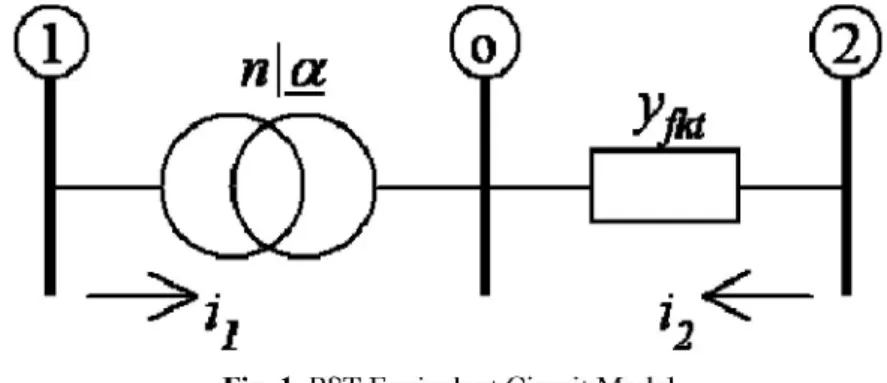
In steady state a PST can be modeled as an ideal transformer having a complex number turn ratio in series with an admittance yfkt=1/xfkt. This model is shown in Figure 1 [5].
Fig. 1. PST Equivalent Circuit Model
An ideal transformer turn ratio can be expressed as v1/vo=nla = n (cosa+jsina) = a+jb. Using an ideal transformer power equation v l i l * = -voio*, following equation system can be formed.
2 [ V i - ( a + j b> 2 ]
a +
b2¡2 = -(a - jb)ii = y
fita + jb
1
(3) (4)
i
The equations above represent primary and secondary sides currents of a PST as voltages. The matrix system of these equations can also be shown as below;
yfkt •yjkt a2
+
b2 ~ yf k ta + jb
a - jb
y fkt (5)If turns ratio is a complex number, the admittance matrix will not be symmetrical. This situation can not be represented by a PI equivalent circuit. If turns ratio is a real number PI equivalent model can be used.
3. VOLTAGE DIP CLASSIFICATION
A classification method described where the dip is characterized by its type, characteristic voltage, PN-factor. The type indicates which phases that are involved in the dip, the characteristic voltage indicates the severity of the dip and the PN-factor quantifies, among others, the impact of rotating machinery on the during fault voltages and the unbalance between the phase voltages. The dip type, Tm, is calculated according to the expression below [6,7].
: Dip type at node m
: Remaining negative sequence voltage at node m
pref (m) : Pre-fault voltage in phase a at node m
V
m : Remaining positive sequence voltage at node m i r n \ T =-60u .arg V —pref (m) v V n (6)
T
Rounding m to the nearest integer results in the following formula list
voltage dip index constructed. Characteristic voltage and PN factor calculation formulas are shown on equations 7.
v
v
2 2
T = 0
m m m m m m m ^V = v
p-v
nF = v
p+ v
nT = 1
^V =
vp+ av" F =
vp -av"
T = 2
^V
7= v
p- a
2.v
nF = v
p+ a
2.v'
m m m m m m nT = 3
^V
7=
vp+ v" F =
vp-v"
m m m m m m mT =
4 ^V = v
p -av" F = v
p+
av"
T_ = 5
^V_ = v
p+ a
2y" F = v
p- a
2y
(7).
J120" Where a • eV
m • Characteristic voltage at node m (pu)
F
m • PN-factor at node m (pu)
For 3 phase faults the characteristic voltage, as well as the PN-factor, are equal to the remaining positive sequence voltage.
4.THE EFFECTS OF PST IN POWER CONTROL
A PST is considered as a series voltage source of which phase angle and magnitude varies. For the reason in steady state a PST can be used to realize following objectives [8]:
1. Power flow regulation can be established.
2. Loop flow control by preventing power to flow unwanted paths. 3. Sharing power on parallel lines.
Two simulation programs (SIMPOW and PSAT) are used to make simulation studies in 9 bus system which is shown in Figure 3.
SIMPOW is a program that can make digital simulation and analysis of electrical power systems. It is developed by ABB and in 2004 transferred to STRI. [9]. PSAT program is also a power system analysis program designed as MATLAB sub-program developed by Federico Milano from Waterloo University [10].
MJH^
Fig. 2. 9-bus test system [11]
The results of simulation studies shows that the two power system programs defined above are reliable for PST studies.
To determine PST effect on power flow a PST with a reactance 0.02 pu is inserted in front of the line between bus 9 and 6 as shown in Figure 3. In 9-bus system, transformers that are connected to bus 1, 2 and 3 are not considered as PST because they are not in parallel system to regulate, to share and to control power.
A. Transmission Line Power Control
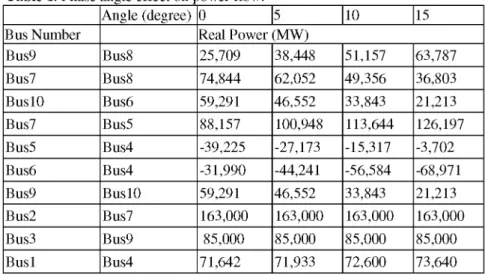
Power flows in system are examined for four different phase angle of PST which located between bus 9 and bus 10. The results are given in Table 1.
Table 1. Phase angle effect on power flow.
Angle (degree) 0 5 10 15 Bus Number Real Power (MW)
Bus9 Bus8 25,709 38,448 51,157 63,787 Bus7 Bus8 74,844 62,052 49,356 36,803 Bus10 Bus6 59,291 46,552 33,843 21,213 Bus7 Bus5 88,157 100,948 113,644 126,197 Bus5 Bus4 -39,225 -27,173 -15,317 -3,702 Bus6 Bus4 -31,990 -44,241 -56,584 -68,971 Bus9 Bus10 59,291 46,552 33,843 21,213 Bus2 Bus7 163,000 163,000 163,000 163,000 Bus3 Bus9 85,000 85,000 85,000 85,000 Bus1 Bus4 71,642 71,933 72,600 73,640 If Table 1 is examined it can be seen that the phase angle shift doesn't effect the production at busses 1,2, and 3. It can also be seen that power flow can be controlled as desired.
As can be seen from the results PST doesn't have an effect on reactive power flow. Reactive power variations can only be reached with under load tap changers.
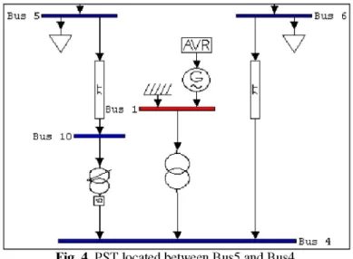
B.Loop Flow Control
In complex grids the power that is needed according to loading, will come from other busses that have different impedances. This results an uncontrolled power flow. By using PST required power can be supplied from one point and the other power flows can be remained the same. To represent this situation a PST is placed in the beginning of the line that lies between busses 4 and 5.
Fig. 4..PST located between Bus5 and Bus4.
Power flow are decreasing and increasing load at bus 6 by %50 are analyzed and shown in Table 2.
Table 2. Load variation effect on power flow.
Load(%) 50 100 150 Bus Real Power (MW)
Bus9 Bus8 31,637 25,709 19,700 Bus7 Bus8 68,883 74,844 80,899 Bus9 Bus6 53,363 59,291 65,300 Bus7 Bus5 94,117 88,157 82,101 Bus5 BuslO -33,595 -39,225 -44,972 Bus6 Bus4 7,330 -31,99 -71,269 Bus10 Bus4 53,363 59,291 65,300 Bus2 Bus7 163 163 163 Bus3 Bus9 85 85 85 Busl Bus4 26,502 71,642 117,388 As seen from table 2, all power flows varies due to load variation. Power variation at one bus has an effect the whole system according to impedances. To form a controlled power flow it is considered that the load supplies from only bus 4 via bus 6 and to achieve this 2.4° phase shift at % 150 loads and -2.3° phase shift at % 50 loads are calculated. These situations are given in Table 3.
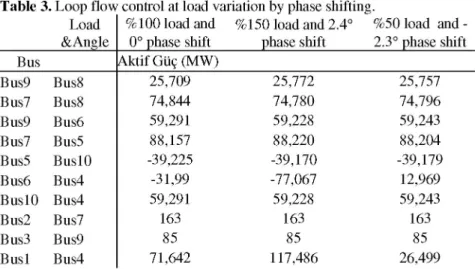
Table 3. Loop flow control at load variation by phase shifting.
Load %100 load and %150 load and 2.4° %50 load and -&Angle 0° phase shift phase shift 2.3° phase shift Bus Aktif Güç (MW) Bus9 Bus8 25,709 25,772 25,757 Bus7 Bus8 74,844 74,780 74,796 Bus9 Bus6 59,291 59,228 59,243 Bus7 Bus5 88,157 88,220 88,204 Bus5 Bus10 -39,225 -39,170 -39,179 Bus6 Bus4 -31,99 -77,067 12,969 Bus10 Bus4 59,291 59,228 59,243 Bus2 Bus7 163 163 163 Bus3 Bus9 85 85 85 Bus1 Bus4 71,642 117,486 26,499 Power flows and required phase shift values are directly relevant to PST impedance as seen from equation (2).
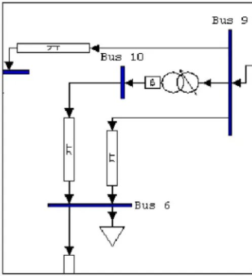
The above figure explains table 3. Items in table 3 represents power flows at determined phase shifts according to load variation at bus 6 and it shows that power flow changes only between bus 4 and bus 6 which load varies. This means, by accurately adjusting the phase shift power can be delivered from required path so no loop flows occur and the lines can be optimum designed.
Fig. 5. Power flow in load variation by using a PST C. Sharing power on parallel lines
On 9-bus system, in order to simulate power sharing, the line between bus 9 and bus 6 is designed as a parallel line and totally has the same reactance as previous. PST is placed on the line that has lower reactance. Power flows in
this situation and to achieve equal power transfer, power flows at phase shift 0° and 5° are given in Table 4.
Fig. 6. Arrangement of 9-bus system to show power sharing capability of a
PST in parallel lines.
Table 4. Flows at 0o and 5o phase shift.
BUS NUMBER Power flows at 0° phase shift Power flows at 5° phase shift Bus9 Bus8 29,5605 39,9991 Bus7 Bus8 71,0664 60,586 Bus10 Bus6 41,2549 22,6371 Bus7 Bus5 91,9336 102,414 Bus5 Bus4 -35,5444 -25,6639 Bus6 Bus4 9,1987 -1,0983 Bus9 Bus6 14,1845 22,3638 Bus9 Bus10 41,2549 22,6371 Bus2 Bus7 163 163 Bus3 Bus9 85 85 Busi Bus4 27,2262 27,6388
As seen from the table the power flows between Bus9-Bus10 and Bus9-Bus6 are equalized at 5° phase shift. This means the lines can be loaded up to their thermal limits with power control ability. Also other power flows must be observed to stay in desired limits.
5. THE EFFECT OF PST VOLTAGE DIP
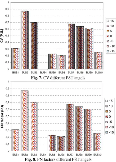
Different fault types are applied at the fault positions one at the time and the remaining voltages at the customer locations in the network are calculated. In the current version all nodes in the network are chosen as fault positions. Voltage dip results in system are examined for seven different phase angle (from 150 to -150 steps by 50) of PST which located between bus 9 and bus 10. The results are given at following graphics. Although all different short circuit conditions are applied to test system, explain the problem severity on BUS4 graphics are illustrated. First of all three phase short circuit applied the BUS4 and calculated CV and PN factor values. These graphic are shown Figure 7 and Figure 8.
0,9 0,8 0,7 D £L 0,6 O 0,5 O 0,5 z 0,4 Q. 0,3 0,2 0,1 0 • 15 • 10 • 5 • 0 • -5 • -10 • -15
BUS1 BUS2 BUS3 BUS4 BUS5 BUS6 BUS7 BUS8 BUS9 BUS10
Fig. 7. CV different PST angels
• 15 • 10 • 5 • 0 • -5 • -10 • -15
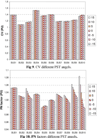
BUS4 voltage is zero and the others voltages are under the 1 pu value. In spite of the fact that PST angle is control the power flow, PST angle is not affected the voltage dip when the three phase short circuit occurred. On the contrary, single phase the ground fault is occurred at the bus of BUS4, PN factor is affected the PST control angle.
1,4 1,2 1 0,8 0,6 0,4 1,1
BUS1 BUS2 BUS3 BUS4 BUS5 BUS6 BUS7 BUS8 BUS9 BUS10
Fig 9. CV different PST angels.
3 1,04 Q. 1,02 0,94 • 15 • 10 • 5 • 0 • -5 • -10 • -15 • 15 • 10 • 5 • 0 • -5 • -10 • -15
BUS1 BUS2 BUS3 BUS4 BUS5 BUS6 BUS7 BUS8 BUS9 BUS10
Fig 10. PN factors different PST angels.
A single line to ground fault gives higher value for characteristic magnitude than a three phase fault. The difference can be thought as due to additional impedance between the point of common coupling (PCC) and the fault. All buses PN factor are changed after PST angled changed. Especially, production
1,8 1,6 --0,2 0 0,98 0,96
bus of GEN3 PN factor values are changed deviation of PST control angles. This situation must be considered system planning.
6. CONCLUSION
Existing transmission systems are loaded up to their performance capacity to take maximum efficiency. To achieve a safe and reliable operation, power flow regulation is inevitable. In this study that a PST is capable of assisting power flow control and in load variation a PST can adjusted to flow power from desired path with preventing loop flows. So power is not passes from unwanted paths and transmission system can be efficiently used. It is also seen that a PST can be effectively used in power sharing on parallel systems. System planners must aware of when PST control angel changes, buses PN factors changed.
REFERENCES
[1] W. Setlinger, "Phase Shifting Transformers", Vatech Transmission And Distribution, 2001.
[2] Edris, A., Mehraban, A.S.B., Rahman, M., Gyugyi, L., Arabi, S., Rietman, T.R., Controlling the Flow of Real and Reactive Power. IEEE Computer Applications in Power, 1998.
[3] Hingorani, N.G., Gyugyi, L Understandig FACTS, IEEE Press., 2000.
[4] ANSI/IEEE, Guide for the Application, Specification and Testing of Phase-Shifting Transformers, ANSI/IEEE C57.135-2001, Institute of Electrical and Electronics Engineers, Piscataway, NJ, 2001.
[5] P. Kundur, "Power System Stability and Control", 1994.
[6] M.H.J. Bollen, L.D. Zhang, "Different methods for classification of three-phase unbalanced voltage dips due to faults - Electric power systems research", Vol.66, No.1, July 2003, pp.59-69.
[7] L.D. Zhang, M.H.J. Bollen, "Characteristics of voltage dips (sags) in power systems", IEEE Transactions on Power Delivery, Vol.15, no.2 (April 2000), pp.827-832.
[8] "Review of Semiconductor Controlled Phase Shifters for Power System Applications", IEEE Transactions on Power Systems, Vol. 9, No.4, Nov. 1994. [9] SIMPOW Power System Simulation & Analysis Software, Release 10.2, Copyright(c) STRI AB, 2004.
[10] M.Federico, Power System Analysis Toolbox Documentation for PSAT version 1.3.0 2004.
[11] P. Andersen, A. A. Fouad "Power System Control and Stability", IEEE PRESS Power Systems Engineering Series, 1994.
Bora ALBOYACI received the B.S. degree in electrical engineering in 1995 from the Technical University of Yildiz. He received the M.S. and Ph.D. degrees in electrical engineering in 1998 and 2001 from The University of Kocaeli respectively. From 1995 to 1996, he worked for TEMAS Consulting Engineering, and his last position was a Consultant Engineer. Since 2001, he has been working as an Assoc.Prof.Dr. at The university of Kocaeli. He is leading two projects at the same university as the power quality of distribution systems and distribution transformer loading evaluations. Tel:+90.262.3351148/1260 Fax:+90.262.3352812 The University of Kocaeli, Department of Electrical Engineering, Veziroglu Campus, 41100 Izmit/TURKEY.
Elif INAN was born in Tekirdağ in Turkey, on March 5, 1980. She received the B.Sc. and M.Sc. degrees in electrical engineering in 2002 and 2005 from The University of Kocaeli respectively. She is a PhD. Student at The University of Kocaeli. Since 2003, she has been working as a research assistant at The University of Kocaeli. Her areas of interest include power flow, power quality, voltage dip.Tel:+90.262.3351148/1286 Fax:+90.262.3352812 The University of Kocaeli, Department of Electrical Engineering, Veziroğlu Campus, 41100 Izmit/TURKEY.
![Fig. 2. 9-bus test system [11]](https://thumb-eu.123doks.com/thumbv2/9libnet/3898074.43600/6.892.259.669.246.595/fig-bus-test-system.webp)