Observation of cavity
structures in composite
metamaterials
Humeyra Caglayan
Ekmel Ozbay
Observation of cavity structures in composite
metamaterials
Humeyra Caglayan and Ekmel Ozbay
Bilkent University, Department of Physics, Department of Electrical and Electronics Engineering, Nanotechnology Research Center – NANOTAM
Bilkent, 06800 Ankara, Turkey [email protected], [email protected]
Abstract. We investigate the cavity structure by the deformation of a unit cell of a
Composite Metamaterial (CMM) structure. We presented different cavity structures with different resonance frequencies and Q-factors. We observed the Q-factor of the cavity resonance as 108 for a CMM based single cavity wherein the cavity structure is a closed ring structure. We investigated the reduced photon lifetime and observed that at the cavity resonance, the effective group velocity was reduced by a factor of 20 for a CMM based single cavity compared to the electromagnetic waves propagating in free space. Since the unit cells of metamaterials are much smaller than the operation wavelength,
subwavelength localization is possible within these metamaterial cavity structures. In the present paper, we showed that the electromagnetic field is localized into a region of λ/8, where λ is the cavity resonance wavelength. Subsequently, we brought two cavities together with an intercavity distance of two metamaterial unit cells and then investigated the transmission spectrum of CMM based interacting 2-cavity system. Finally, using the tight-binding picture we observed the normalized group velocity corresponding to the coupled cavity structure.
Keywords: metamaterials, cavity, localization, coupled cavity.
1 INTRODUCTION
The electromagnetic (EM) response of a homogeneous material is determined by two parameters. One of these parameters is permittivity (ε) which describes the response of a material to the electric component of an EM wave. The other one is permeability (μ), which is related to the response of the magnetic component. However, the index of refraction which is defined as n= εμ, is the more commonly used EM parameter. The index of refraction is positive for naturally occurring materials. However, there is a secret garden of electromagnetism that was first realized by the Russian physicist Vector Veselago. Veselago proposed that if a material were found that had ε < 0 and μ< 0, then its index of refraction would also be negative, n < 0 over a certain frequency range [1]. However, this idea had to wait more than 30 years to be confirmed experimentally. The discovery of Split Ring Resonator (SRR) by Pendry in 1999 enabled the possibility for the experimental verification of this idea[2].
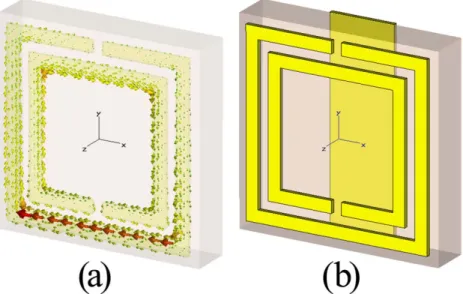
An SRR response to the magnetic component of the EM field is used as the element to obtain negative µ. The working principle of the SRR is very similar to an LC resonator. A time varying magnetic field that is polarized perpendicular to the plane of the SRR will induce circulating currents according to Faraday’s law (Fig.1 (a)). Although obtaining negative µ is an issue because of the lack of magnetic charge, it is possible to obtain negative µ by using SRR structures.
Obtaining negative ε is easier because it has been known for centuries that naturally occurring materials yield a negative response to the electric component of light. Any metal below its plasma frequency (ωp) yields negative permittivity values. Many decades
ago researchers fabricated structures that had ε < 0 by using arrays of conducting wires [3, 5]. This technology was recently reintroduced in which metallic thin wires are used for
obtaining negative ε below plasma frequency [6, 7]. Because the plasma frequency can be tuned by geometry, it is possible to obtain negative ε at nearly any frequency range, from microwave to optical
Fig. 1. (a) The surface currents unit cell of the SRR structure. (b) The unit cell of the CMM structure. The unit cells of metamaterials are much smaller than the
operating wavelength.
.
In having identified the artificial structures that can separately provide ε< 0 and μ< 0, we can combine the two and construct a negative index material. Veselago pointed out that a medium having a negative index of refraction would exhibit unusual physical properties. The phase velocity of a wave is reversed in negative index materials; the Doppler shift of a source relative to a receiver is reversed; Cerenkov radiation that is emitted by a moving charged particle is in the backward rather than the forward direction; radiation pressure is reversed in order to become a radiation tension; converging lenses become diverging lenses and vice versa.
In such a medium the electric, magnetic, and wave vector components form a left-handed coordinate system; hence the name left-left-handed metamaterial (LHM) is used. This idea was experimentally investigated by the construction of a Composite Metamaterial (CMM) comprising two components that simultaneously have ε<0 and µ< 0 over a certain frequency range [8]. This experiment sparked the rapidly growing interest in metamaterials. There are also many experimental and theoretical works that have been reported for novel applications of metamaterials, such as negative refraction [9], subwavelength imaging [10], cloaking [11], and reverse Doppler shift [12].
In addition to the negative index of refraction, metamaterials have another important property: the typical size of these resonant inclusions is approximately 10 times smaller than the vacuum wavelength of the light at the resonance frequency. The electromagnetic properties of such optical-scale subwavelength structures can then be evaluated by using an effective medium approximation. This property can also lead to different novel applications, such as the localization of the field into a subwavelength region. Recently, the localization of the field has attained great interest from the scientific community, since it is the key issue of several applications. One method for obtaining a localized field is to make a deformation in a unit cell of the periodic structure [13, 14].
In this paper, we investigated the defect formation in CMMs. First of all, we presented the transmission retrieval results of a CMM structure. Subsequently, we introduced 6 different defect structures and transmission results for these structures. Our results show that the strong modification of a unit cell of the metamaterial can exhibit a defect resonance. We presented the photon lifetime and localized electric field at the defect
resonance. Moreover, we brought two cavities together with an intercavity distance and investigated the transmission spectrum and reduced group velocity at the cavity resonance. Although we studied at microwave regime, this study can be scaled down to other regimes. Metamaterials are geometrically scalable, thus offering a wide range of operation frequencies including radio [15, 16], microwave [17, 29], millimeter-wave [30], far infrared (IR) [31], mid-IR [32, 33], near-IR frequencies [34, 37] and even visible wavelengths [38, 39].
2 SINGLE CAVITY SYSTEM
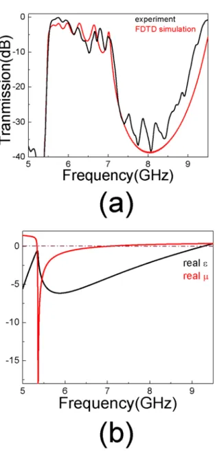
Fig. 2. (a) The measured transmission of the CMM structure has a transmission peak from 5.5-7.0 GHz. The calculated transmission is in good agreement with the measured result. (b) The effective ε and µ were derived from the calculated transmission and reflection coefficients. The calculated parameters show that CMM structure possesses effective ε<0, µ<0 from 5.4-7.0 GHz and ε<0, µ>0
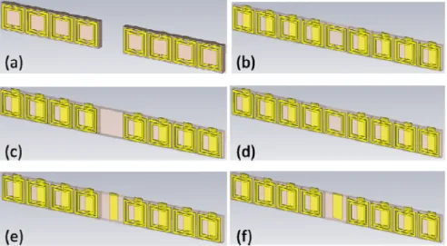
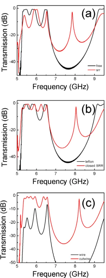
Fig. 3. We defined 6 different deformations in the periodic system. (a) We obtained the first defect structure by removing the center unit cell. We defined
the other 5 defect structures by changing the center unit cell with these structures: (b) SRR, (c) Teflon, (d) closed SRR, (e) wire, and (f) cut-wire.
The metamaterial medium that we used in the present study was composed of a 1D periodic arrangement of wire stripes and square SRR structures. The wire stripes were printed on the back of Teflon (ε = 2.17) substrates, and the square SRR were printed on the front faces (Fig. 1 (b)). The thickness of the Teflon substrate was 1mm. The thickness of the metal (copper) was 0.05 mm. The width of the wire stripes was 1.6 mm. The lattice constant along the x direction was 4.95 mm and along the x direction (propagation direction) it was 2 mm. There were 40 layers along the y and z directions and 8 layers along the propagation direction. The E-field was in the y direction. The experimental setup consisted of an HP 8510C network analyzer and two standard gain horn antennae in order to measure the transmission amplitude. The measured transmission demonstrates that this CMM structure has a transmission peak from 5.5-7.0 GHz. We calculated the transmission using the commercial software program CST Microwave Studio®. The calculated transmission is in good agreement with the measured result (Fig. 2 (a)).
We calculated the effective ε and µ of the CMM structure by using the retrieval procedure. The retrieval procedure is widely used in order to calculate the effective parameters of the metamaterials. In this method, the real and imaginary parts of the refractive index, wave impedance and, therefore, the real and imaginary parts of the ε and µ are retrieved from the amplitude, and the phase information of the transmission and reflection. The details of the retrieval procedure that were used in the present study are outlined in Refs.40. This particular method has the advantage of identifying the correct branch of the effective ε and µ. The ambiguity in the determination of the correct branch is resolved by the use of an analytic continuation procedure. There was one layer of the structure along the propagation direction in this calculation. We employed periodic boundary conditions along directions other than the propagation direction. Therefore, the simulation setup coincides with a slab of material that consists of a single layer. The effective ε and µ were derived from the transmission and reflection coefficients. The calculated parameters show that the CMM structure possesses effective ε<0, µ<0 from 5.4-7.0 GHz and ε<0, µ>0 from 7.0-9.4 GHz (Fig. 2 (b)).
In order to break the symmetry of these periodic composite metamaterials, we changed the center unit cell of the structures and made a deformation in the CMM structure. We defined 6 different deformations in the periodic system. The schematics of the cavity structures are presented in Fig. 3. We obtained the first defect structure by removing the center unit cell. However, we could not obtain a defect resonance on the transmission spectrum (Fig. 4 (a)). Hence, this deformation is not strong enough to break
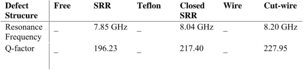
the symmetry of the system. We defined the other 5 defect structures by changing the center unit cell with these structures: Teflon, wire, SRR, closed SRR and cut-wire. The transmission spectrum for these CMM based defect structures are shown in Fig. 4. The resonance frequencies and Q-factors (quality factor, defined as the center frequency, and divided by the full width at half maximum) are shown in Table. 1.
Table 1. The resonance frequencies and Q-factors (quality factor, defined as the center frequency, and divided by the full width at half maximum) of the CMM based cavity structures.
Defect Strucure
Free SRR Teflon Closed SRR
Wire Cut-wire
Resonance
Frequency _ 7.85 GHz _ 8.04 GHz _ 8.20 GHz
Q-factor _ 196.23 _ 217.40 _ 227.95
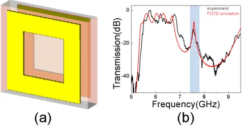
On the other hand, we defined a different defect structure that is easier in terms of fabrication. This defect structure comprises closed rings on both sides of the Teflon board. The structure of the defect is shown in Fig. 5. The defect resonance is at 7.5 GHz with a Q-factor of 108. We used this defect structure in the rest of the present paper.
The reflection of the CMM structure is very high in the negative ε (and positive µ) frequency range and, therefore, the CMM structures on both sides of the cavity behave like frequency-specific mirrors[41, 42]. The reflections of the EM waves between these two mirrors interfere constructively and destructively, giving rise to a standing wave pattern between the mirror surfaces, just as in Fabry-Perot resonances.
A medium with a reduced group velocity, or in other words a medium with increased photon lifetime, offers a promising tool to increase the spontaneous emission rate and efficiency of nonlinear processes. Therefore, metamaterial based cavities with a controllable group velocity can bring significant advantages to optoelectronic devices. An HP-8510C vector network analyzer is used in our measurements. HP-8510C network analyzer is capable of measuring both intensity and phase. The phase information obtained from the measurement is used to determine the delay time or the photon lifetime. The photon lifetime is defined as . Here, φ is the net phase difference between the phase of the EM waves propagating inside the structure and the phase of the EM waves propagating in free space for a total structure length. The photon lifetime corresponds to the propagation time of the EM waves inside the structure. The effective group velocity is inversely proportional to the photon lifetime and is defined as where L is the cavity length. The measured photon lifetime is 3 ns for a CMM cavity structure (Fig. 6). This also means that, at the cavity resonance, the effective group velocity is reduced by a factor of 20 for a CMM cavity when compared to the electromagnetic waves propagating in free space. The Q-factor and effective group velocity reduction factor are related through the localization of EM waves.
The calculated electric field distributions for the cavity structures show that the EM waves at the cavity resonance are trapped in the positive index region. The length of the cavity is only λ/8, where λ is the cavity resonance wavelength. Hence, the field at the cavity resonance is enhanced at the subwavelength cavity region (Fig. 7). Such a structure with enhanced electromagnetic fields can be used for several applications, including nonlinear optics.
Fig. 4. We defined different defect structures by changing the center unit cell with these structures: Teflon, wire, SRR, closed SRR and cut-wire. We observed cavity resonance for some of these CMM based defect structures.
Fig. 5. (a) The unit cell of the defect structure used in the rest of this study consists of closed rings on both side of the Teflon board. (b) The transmission
spectrum shows that the defect resonance is at 7.5 GHz with Q-factor of 108.
Fig.6 . The photon lifetime is increased at the cavity resonance of the CMM based single cavity. Hence, the effective group velocity is reduced by a factor of
20 for the CMM cavity when compared to the electromagnetic waves propagating in free space.
Fig. 7. The calculated electric field is highly localized at the cavity region for CMM based cavity structure. The field at the cavity region is localized to a
3 TWO CAVITY SYSTEM
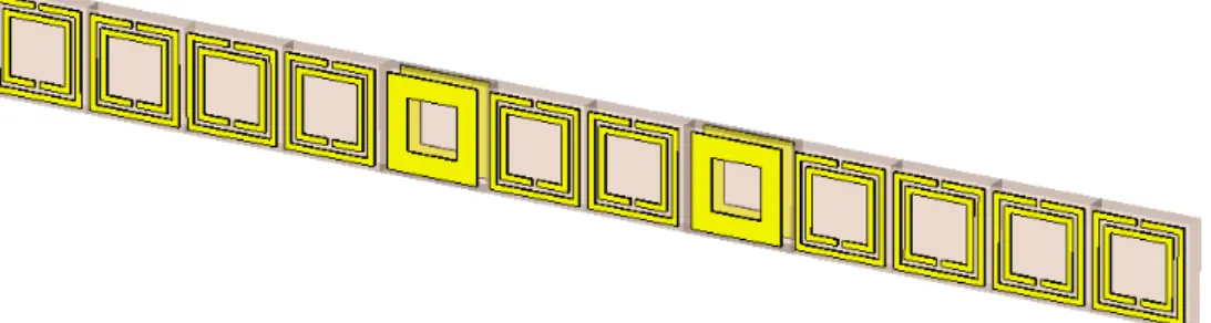
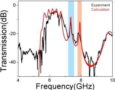
Moreover, we brought two cavities together with an intercavity distance of two metamaterial unit cells. The total two-cavity system contains two cavities and four metamaterial unit cells at each side of each cavity (2 cavities+ 8 metamaterial unit cells) in the propagation direction. The schematic of the two-cavity system is presented in Fig. 8. For two coupled cavities, the transmission characteristics as a function of frequency are measured and calculated. As shown in Fig. 9, we observed that the resonance modes are split into two distinct symmetric and antisymmetric modes that are similar to a PC cavity structure. In PC cavity structures, when two isolated cavities are brought together the localized photon modes should overlap. Due to this interaction, the doubly degenerate eigenmode splits into two distinct modes as: symmetric and antisymmetric. These modes are reminiscent of the bonding and antibonding states in solid state physics. For example, in the diatomic molecules, the interaction between the two atoms produces a splitting of the degenerate atomic levels into bonding and antibonding orbitals. The measured values of resonance frequencies are ω1 = 7.3 GHz and ω2 = 7.9 GHz for the CMM based 2-cavity
structure.
Fig. 8. The total two-cavity system contains two cavities and four metamaterial unit cells at each side of each cavity (2 cavities+ 8 metamaterial unit cells) in
the propagation direction.
The classical wave analog of the tight-binding (TB) picture has successfully been applied to photonic structures [43, 44]. By using the direct implications of the TB picture, a novel propagation mechanism for photons along the localized coupled cavity modes in photonic crystals was proposed and demonstrated [45, 46]. In these structures, photons can hop from one tightly confined mode to the neighboring one due to the weak interaction between them. The same approach can be applied to metamaterial based coupled cavities. Using the TB picture, it is possible to obtain eigenvalues and eigenvectors corresponding to two coupled cavity structures. Hence, the dispersion relation and group velocity can be obtained, keeping only the nearest-neighbor coupling terms as: (1) )] cos( 1 [ ) (k =Ω +κ kΛ ω (2) ) sin( ) (k =∇k k =− ΛΩ kΛ g ω κ ν
Here, κ is a TB parameter that can be obtained from the splitting of the eigenmodes of two coupled cavities, in which Ω is the frequency mode of the single cavity and Λ is the distance between the two cavity structures (intercavity distance).
The calculated TB parameter is κ = -0.07 for CMM based coupled cavities. We can obtain the dispersion relation of the coupled cavity structures by using these TB parameters and Λ = 9.9 mm (2 metamaterial unit cells). Figure 10 (a) shows the calculated dispersion relation ω(k). We also plotted the normalized group velocity corresponding to the coupled cavity structure. As shown in Fig.10 (b), the group velocity has a maximum
value of nearly one-hundredth the speed of light in vacuum, at the coupled-cavity band center, and vanishes at the band edges.
Fig. 9: The measured (black curve) and calculated (red curve) transmission spectrum for CMM based coupled cavity. The measured values of resonance frequencies are ω1 = 7.3 GHz and ω2 = 7.9 GHz for the CMM based 2-cavity
structure.
Fig. 10: (a) The calculated dispersion relation of the CMM based coupled cavity structure. (b) The group velocity is two orders of magnetitude slower than the speed of light at the bend center and vanishes at the band edges.
4 CONCLUSION
In conclusion, we showed that it is possible to obtain a cavity structure by the deformation of a unit cell of a CMM structure. We also showed that the deformation has to be strong enough to obtain a defect resonance in the transmission spectrum. We investigated different defect structures and obtained a defect resonance at 7.5 GHz with a Q-factor of 108 with a closed ring defect structure. Moreover, we presented at the cavity resonance, the effective group velocity reduced by a factor of 20 for a CMM cavity when compared
to the electromagnetic waves propagating in free space in which the field is enhanced at the subwavelength cavity region. The transmission properties of the CMM based 2-cavity system are investigated. Due to the coupling between the strongly localized cavity modes, the single-cavity mode splits in two distinct modes. Finally, by using the TB picture we observed the normalized group velocity corresponding to the coupled cavity structure. Acknowledgments
This work is supported by the European Union under the projects PHOME, and EU-ECONAM, and TUBITAK under the project nos. 106E198, 107A004, and 107A012. One of the authors (E.O.) also acknowledges partial support from the Turkish Academy of Sciences.
References
[1] V. G. Veselago, "The electrodynamics of substances with simultaneously negative values of permittivity and permeability," Sov. Phys. Usp. 10, 504-509 (1968) [doi:10.1070/PU1968v010n04ABEH003699].
[2] J. B. Pendry, A. J. Holden, D. J. Robbins, and W. J. Stewart, "Magnetism from conductors and enhanced nonlinear phenomena," IEEE Tran. on Microwave Theory and Tech. 47, 2075-2084 (1999) [doi: 10.1109/22.798002].
[3] R. Bracewell, "Analogues of an ionized medium," Wireless Eng. 31, 320–326 (1954).
[4] W. Rotman, "Plasma simulation by artificial dielectrics and parallel-plate media," IRE Trans. on Antennas and Propag. 10, 82-95 (1962) [doi:10.1109/TAP.1962.1137809].
[5] R. Ulrich, "Far-infrared properties of metallic mesh and its complementary structure," Infrared Phys. 7, 37-55 (1967) [doi: 10.1016/0020-0891(67)90028-0]. [6] J. B. Pendry, A. J. Holden, W. J. Stewart, and I. Youngs, "Extremely low
frequency plasmons in metallic mesostructures," Phys. Rev. Lett. 76, 4773-4776 (1996) [doi: 10.1103/PhysRevLett.76.4773].
[7] J. B. Pendry, A. J. Holden, D. J. Robbins, and W. J. Stewart, "Low frequency plasmons in thin-wire structures," J. Phys.: Condens. Matter 10, 4785-4809 (1998) [doi: 10.1088/0953-8984/10/22/007].
[8] D. R. Smith, W. J. Padilla, D. C. Vier, S. C. Nemat-Nasser, and S. Schultz, "Composite medium with simultaneously negative permeability and permittivity," Phys. Rev. Lett. 84, 4184-4187 (2000) [doi:
10.1103/PhysRevLett.84.4184].
[9] E. Ozbay, I. Bulu, and H. Caglayan, "Transmission, refraction, and focusing properties of labyrinth based left-handed metamaterials," Phys. Status Solidi B
244, 1202-1210 (2007) [doi:10.1002/pssb.200674507].
[10] I. Bulu, H. Caglayan, and E. Ozbay, "Experimental demonstration of subwavelength focusing of electromagnetic waves by labyrinth-based two-dimensional metamaterials," Opt. Lett. 31, 814-816 (2006) [doi:
10.1364/OL.31.000814]
[11] D. Schurig, J. J. Mock, B. J. Justice, S. A. Cummer, J. B. Pendry, A. F. Starr, and D. R. Smith, "Metamaterial electromagnetic cloak at microwave frequencies," Science 314, 977-980 (2006) [doi:10.1126/science.1133628]
[12] A. Belyantsev and A. Kozyrev, "Reversed doppler effect under reflection from a shock electromagnetic wave," Tech. Phys. 47, 1477-1480 (2002) [doi:
10.1134/1.1522123].
[13] H. Caglayan, I. Bulu, M. Loncar, and E. Ozbay, "Cavity formation in split ring resonators," Photon. and Nanostruct.-Fund. and App. 6, 200-204 (2008) [doi: 10.1016/j.photonics.2008.09.001].
[14] X. D. Chen, T. M. Grzegorczyk, B. I. Wu, J. Pacheco, and J. A. Kong, "Robust method to retrieve the constitutive effective parameters of metamaterials," Phys. Rev. E 70, 016608 (2004) [doi: 10.1103/PhysRevE.70.016608].
[15] M. C. K. Wiltshire, J. B. Pendry, and J. V. Hajnal, "Sub-wavelength imaging at radio frequency," J. Phys.: Cond. Matt. 18, L315-L321 (2006) [doi:
10.1088/0953-8984/18/22/L06].
[16] M. C. K. Wiltshire, J. B. Pendry, I. R. Young, D. J. Larkman, D. J. Gilderdale, and J. V. Hajnal, "Microstructured magnetic materials for rf flux guides in magnetic resonance imaging," Science 291, 849-851 (2001) [doi:
10.1126/science.291.5505.849].
[17] R. A. Shelby, D. R. Smith, S. C. Nemat-Nasser, and S. Schultz, "Microwave transmission through a two-dimensional, isotropic, left-handed metamaterial," Appl. Phys. Lett. 78, 489-491 (2001) [doi:10.1063/1.1343489].
[18] M. Bayindir, K. Aydin, E. Ozbay, P. Markos, and C. M. Soukoulis,
"Transmission properties of composite metamaterials in free space," Appl. Phys. Lett. 81, 120-122 (2002) [doi:10.1063/1.1492009].
[19] A. Grbic and G. V. Eleftheriades, "Experimental verification of backward-wave radiation from a negative refractive index metamaterial," J. Appl. Phys. 92, 5930-5935 (2002) [doi:10.1063/1.1513194].
[20] A. A. Houck, J. B. Brock, and I. L. Chuang, "Experimental observations of a left-handed material that obeys snell's law," Phys. Rev. Lett. 90, 137401 (2003) [doi: 10.1103/PhysRevLett.90.137401].
[21] K. Li, S. J. McLean, R. B. Greegor, C. G. Parazzoli, and M. H. Tanielian, "Free-space focused-beam characterization of left-handed materials," Appl. Phys. Lett.
82, 2535-2537 (2003) [doi: 10.1063/1.1567454].
[22] C. G. Parazzoli, R. B. Greegor, K. Li, B. E. C. Koltenbah, and M. Tanielian, "Experimental verification and simulation of negative index of refraction using snell's law," Phys. Rev. Lett. 90, 107401 (2003)
[doi:10.1103/PhysRevLett.90.107401].
[23] K. Aydin, K. Guven, M. Kafesaki, L. Zhang, C. M. Soukoulis, and E. Ozbay, "Experimental observation of true left-handed transmission peaks in
metamaterials," Opt. Lett. 29, 2623-2625 (2004) [doi: 10.1364/OL.29.002623]. [24] K. Aydin, K. Guven, N. Katsarakis, C. M. Soukoulis, and E. Ozbay, "Effect of disorder on magnetic resonance band gap of split-ring resonator structures," Opt. Exp. 12, 5896-5901 (2004) [doi: 10.1364/OPEX.12.005896].
[25] N. Katsarakis, T. Koschny, M. Kafesaki, E. N. Economou, E. Ozbay, and C. M. Soukoulis, "Left- and right-handed transmission peaks near the magnetic resonance frequency in composite metamaterials," Phys. Rev. B 70, 201101 (2004) [doi: 10.1103/PhysRevB.70.201101].
[26] N. Katsarakis, T. Koschny, M. Kafesaki, E. N. Economou, and C. M. Soukoulis, "Electric coupling to the magnetic resonance of split ring resonators," Appl. Phys. Lett. 84, 2943-2945 (2004) [doi: 10.1063/1.1695439].
[27] K. Aydin, K. Guven, C. M. Soukoulis, and E. Ozbay, "Observation of negative refraction and negative phase velocity in left-handed metamaterials," Appl. Phys. Lett. 86, 124102 (2005) [doi: 10.1063/1.1888051].
[28] I. Bulu, H. Caglayan, K. Aydin, and E. Ozbay, "Compact size highly directive antennas based on the srr metamaterial medium," New J. Phys. 7, 223 (2005) [doi: 10.1088/1367-2630/7/1/223].
[29] I. Bulu, H. Caglayan, and E. Ozbay, "Experimental demonstration of labyrinth-based left-handed metamaterials," Opt. Exp. 13, 10238-10247 (2005) [doi: 10.1364/OPEX.13.010238].
[30] M. Gokkavas, K. Guven, I. Bulu, K. Aydin, R. S. Penciu, M. Kafesaki, C. M. Soukoulis, and E. Ozbay, "Experimental demonstration of a left-handed metamaterial operating at 100 ghz," Phys. Rev. B 73, 193103 (2006) [doi: 10.1103/PhysRevB.73.193103].
[31] T. J. Yen, W. J. Padilla, N. Fang, D. C. Vier, D. R. Smith, J. B. Pendry, D. N. Basov, and X. Zhang, "Terahertz magnetic response from artificial materials," Science 303, 1494-1496 (2004) [doi: 10.1126/science.1094025].
[32] S. Linden, C. Enkrich, M. Wegener, J. F. Zhou, T. Koschny, and C. M.
Soukoulis, "Magnetic response of metamaterials at 100 terahertz," Science 306, 1351-1353 (2004) [doi: 10.1126/science.1105371].
[33] H. O. Moser, B. D. F. Casse, O. Wilhelmi, and B. T. Saw, "Terahertz response of a microfabricated rod-split-ring-resonator electromagnetic metamaterial," Phys. Rev. Lett. 94, 063901 (2005) [doi: 10.1103/PhysRevLett.94.063901]
[34] V. M. Shalaev, "Optical negative-index metamaterials," Nature Photon. 1, 41-48 (2007) [doi: 10.1038/nphoton.2006.49].
[35] V. M. Shalaev, W. S. Cai, U. K. Chettiar, H. K. Yuan, A. K. Sarychev, V. P. Drachev, and A. V. Kildishev, "Negative index of refraction in optical
metamaterials," Opt. Lett. 30, 3356-3358 (2005) [doi: 10.1364/OL.30.003356]. [36] S. Zhang, W. J. Fan, K. J. Malloy, S. R. J. Brueck, N. C. Panoiu, and R. M.
Osgood, "Near-infrared double negative metamaterials," Opt. Exp. 13, 4922-4930 (2005) [doi: 10.1364/OPEX.13.004922].
[37] S. Zhang, W. J. Fan, N. C. Panoiu, K. J. Malloy, R. M. Osgood, and S. R. J. Brueck, "Experimental demonstration of near-infrared negative-index metamaterials," Phys. Rev. Lett. 95, 137404 (2005) [doi:
10.1103/PhysRevLett.95.137404].
[38] W. S. Cai, U. K. Chettiar, H. K. Yuan, V. C. de Silva, A. V. Kildishev, V. P. Drachev, and V. M. Shalaev, "Metamagnetics with rainbow colors," Opt. Exp.
15, 3333-3341 (2007) [doi: 10.1364/OE.15.003333].
[39] G. Dolling, M. Wegener, C. M. Soukoulis, and S. Linden, "Negative-index metamaterial at 780 nm wavelength," Opt. Lett. 32, 53-55 (2007) [doi: 10.1364/OL.32.000053].
[40] X. Chen, B. I. Wu, J. A. Kong, and T. M. Grzegorczyk, "Retrieval of the effective constitutive parameters of bianisotropic metamaterials," Phys. Rev. E
71, 046610 (2005) [doi: 10.1103/PhysRevE.71.046610].
[41] E. Ozbay, K. Aydin, E. Cubukcu, and M. Bayindir, "Transmission and reflection properties of composite double negative metamaterials in free space," IEEE trans. antennas propag. 51, 2592-2595 (2003) [doi: 10.1109/TAP.2003.817570]. [42] K. Aydin and E. Ozbay, "Experimental investigation of reflection characteristics
of left-handed metamaterials in free space," Iet Microw. Antennas Propag. 1, 89-93 (2007) [ doi: 10.1049/iet-map:20050301].
[43] E. Lidorikis, M. Sigalas, E. Economou, and C. Soukoulis, "Tight-binding parametrization for photonic band gap materials," Phys. Rev. Lett. 81, 1405-1408 (1998) [doi: 10.1103/PhysRevLett.81.1405].
[44] T. Mukaiyama, K. Takeda, H. Miyazaki, Y. Jimba, and M. Kuwata-Gonokami, "Tight-binding photonic molecule modes of resonant bispheres," Phys. Rev. Lett.
82, 4623-4626 (1999) [doi: 10.1103/PhysRevLett.82.4623].
[45] M. Bayindir, B. Temelkuran, and E. Ozbay, "Tight-binding description of the coupled defect modes in three-dimensional photonic crystals," Phys. Rev. Lett.
84, 2140-2143 (2000) [doi: 10.1103/PhysRevLett.84.2140].
[46] M. Bayindir, C. Kural, and E. Ozbay, "Coupled optical microcavities in one-dimensional photonic bandgap structures," J. Opt. A: Pure Appl. Opt. 3, S184-S189 (2001) [doi: 10.1088/1464-4258/3/6/369].
Humeyra Caglayan received the B.S. and M.S. degrees in Physics from the Bilkent
University in Ankara, Turkey in 2003 and 2005, respectively. Under the supervision of Prof. Ekmel Ozbay, during her M.S. thesis, she focused on the enhanced and confined transmission by single subwavelength apertures. She authored and co-authored 31 refereed journal articles. She is currently a senior Ph.D student at the Department of Physics, Bilkent University. She is conducting her research activities at the Bilkent Nanotechnology Research Center. Her research interests are left-handed metamaterials, resonances in split-ring resonator structures, photonic crystals, surface plasmons.
Technical University, Ankara, Turkey in 1983. He received his M.S. and Ph. D. degrees from Stanford University in electrical engineering, in 1989 and 1992. From 1992-1993, he worked as a postdoctoral research associate in Stanford University. His research in Stanford focused on high speed resonant tunneling and optoelectronic devices. Between 1993 and 1995, he worked as a scientist in DOE Ames national laboratory in Iowa State University in the area of photonic band gap materials. He joined Bilkent University (Ankara, Turkey) in 1995, where he is currently a full professor in physics department and also in Department of Electrical and Electronics engineering. His research in Bilkent involves nanophotonics, nanometamaterials, nanoelectronics, nanoplasmonics, nanodevices, photonic crystals, GaN/AlGaN MOCVD growth, fabrication and characterization of GaN based devices, and high speed optoelectronics. He is the 1997 recipient of the Adolph Lomb Medal of Optical Society of America and 2005 European Union Descartes Science award. He is also the recipient of 1995 Parlar Foundation young scientist, 1996 Tugac foundation technology development, 1997 TUBITAK young scientist, 1998 Sedat Simavi Foundation Science, 2006 TUBITAK Science awards. He is working as a topical editor of Optics Letters journal since 2002. He became the editor of Photonics and Nanostructures journal in 2006. He has published 169 articles in SCI journals, and 202 international conference proceedings. His publications have received more than 3000 SCI citations. He holds 2 patents in the area of photonic crystals. He has given 63 invited talks in international conferences. His recent review article on plasmonics appeared as an invited review article in Jan. 12th 2006 issue of Science Magazine. He is currently working as a principal investigator, and executive committee member in 5 EU-FP projects. These include a STREP project EU-DALHM (Development and Analysis of Left Handed Materials), NoE-PHOREMOST (Nanophotonics to realize Molecular-Scale Technologies), and NoE-METAMORPHOSE (MetaMaterials ORganized for radio, millimeter wave, and PHOtonic Superlattice Engineering), ECONAM (Electromagntetic Characterization of Nanostructured Materials), and EU-PHOME (PHOtonic Metamaterials). Besides these EU projects, he is the principal investigator of 10 national projects supported by various funding agencies. He has worked with various high-tech companies in USA, Europe and Turkey. He is currently acting as the national delegate for Turkey in the program committee of EU-NMP (nanotechnologies, manufacturing and processes) which is preparing the workprogramme and the project calls for EU-FP7. He is also working as the national representative for the nanotechnology programs in EU-COST projects.