Asymmetric transmission of linearly polarized
waves and polarization angle dependent wave
rotation using a chiral metamaterial
Mehmet Mutlu,1,* Ahmet E. Akosman,1 Andriy E. Serebryannikov,2 and Ekmel Ozbay1 1Department of Electrical and Electronics Engineering, Nanotechnology Research Center, Bilkent University, 06800
Ankara, Turkey
2Department of Electrical Engineering, E-3, Hamburg University of Technology, D-21071 Hamburg, Germany *[email protected]
Abstract: An electrically thin chiral metamaterial structure composed of
four U-shaped split ring resonator pairs is utilized in order to realize polarization rotation that is dependent on the polarization of the incident wave at 6.2 GHz. The structure is optimized such that a plane wave that is linearly polarized at an arbitrary angle is an eigenwave of the system at this frequency. The analytical relation between the incident polarization and the polarization rotation is derived using transmission matrices. Furthermore, the proposed structure exhibits an asymmetric transmission of linearly polarized waves at 6.2 GHz. Plane waves traveling in opposite but perpendicular directions to the material plane are rotated by different angles. On the other hand, four incident polarization angles have been found for the same structure, at which the transmission is symmetric. The experiment results are in good agreement with the numerical results.
©2011 Optical Society of America
OCIS codes: (160.3918) Metamaterials; (160.1585) Chiral media; (230.5440)
Polarization-selective devices. References and links
1. J. B. Pendry, A. J. Holden, D. J. Robbins, and W. J. Stewart, “Magnetism from conductors and enhanced nonlinear phenomena,” IEEE Trans. Microw. Theory Tech. 47(11), 2075–2084 (1999).
2. D. R. Smith, W. J. Padilla, D. C. Vier, S. C. Nemat-Nasser, and S. Schultz, “Composite medium with simultaneously negative permeability and permittivity,” Phys. Rev. Lett. 84(18), 4184–4187 (2000). 3. V. M. Shalaev, W. Cai, U. K. Chettiar, H. K. Yuan, A. K. Sarychev, V. P. Drachev, and A. V. Kildishev,
“Negative index of refraction in optical metamaterials,” Opt. Lett. 30(24), 3356–3358 (2005).
4. C. G. Parazzoli, R. B. Greegor, K. Li, B. E. C. Koltenbah, and M. Tanielian, “Experimental verification and simulation of negative index of refraction using Snell’s law,” Phys. Rev. Lett. 90(10), 107401 (2003). 5. N. Katsarakis, T. Koschny, M. Kafesaki, E. Economou, E. Ozbay, and C. Soukoulis, “Left- and right-handed
transmission peaks near the magnetic resonance frequency in composite metamaterials,” Phys. Rev. B 70(20), 201101 (2004).
6. N. Fang and X. Zhang, “Imaging properties of a metamaterial superlens,” Appl. Phys. Lett. 82(2), 161–163 (2003).
7. K. Aydin, I. Bulu, and E. Ozbay, “Subwavelength resolution with a negative-index metamaterial superlens,” Appl. Phys. Lett. 90(25), 254102 (2007).
8. K. Aydin, I. Bulu, and E. Ozbay, “Focusing of electromagnetic waves by a left-handed metamaterial flat lens,” Opt. Express 13(22), 8753–8759 (2005).
9. K. Aydin, A. O. Cakmak, L. Sahin, Z. Li, F. Bilotti, L. Vegni, and E. Ozbay, “Split-ring-resonator-coupled enhanced transmission through a single subwavelength aperture,” Phys. Rev. Lett. 102(1), 013904 (2009). 10. I. M. Pryce, K. Aydin, Y. A. Kelaita, R. M. Briggs, and H. A. Atwater, “Highly strained compliant optical
metamaterials with large frequency tunability,” Nano Lett. 10(10), 4222–4227 (2010).
11. K. Aydin and E. Ozbay, “Capacitor-loaded split ring resonators as tunable metamaterial components,” J. Appl. Phys. 101(2), 024911 (2007).
12. J. B. Pendry, “A chiral route to negative refraction,” Science 306(5700), 1353–1355 (2004). 13. M. Decker, M. W. Klein, M. Wegener, and S. Linden, “Circular dichroism of planar chiral magnetic
metamaterials,” Opt. Lett. 32(7), 856–858 (2007).
14. Z. Li, K. B. Alici, E. Colak, and E. Ozbay, “Complementary chiral metamaterials with giant optical activity and negative refractive index,” Appl. Phys. Lett. 98(16), 161907 (2011).
15. S. Zhang, Y. S. Park, J. Li, X. Lu, W. Zhang, and X. Zhang, “Negative refractive index in chiral metamaterials,” Phys. Rev. Lett. 102(2), 023901 (2009).
16. J. Dong, J. Zhou, T. Koschny, and C. Soukoulis, “Bi-layer cross chiral structure with strong optical activity and negative refractive index,” Opt. Express 17(16), 14172–14179 (2009).
17. J. Zhou, J. Dong, B. Wang, T. Koschny, M. Kafesaki, and C. M. Soukoulis, “Negative refractive index due to chirality,” Phys. Rev. B 79(12), 121104 (2009).
18. E. Plum, J. Zhou, J. Dong, V. A. Fedotov, T. Koschny, C. M. Soukoulis, and N. I. Zheludev, “Metamaterial with negative index due to chirality,” Phys. Rev. B 79(3), 035407 (2009).
19. Z. Li, R. Zhao, T. Koschny, M. Kafesaki, K. B. Alici, E. Colak, H. Caglayan, E. Ozbay, and C. M. Soukoulis, ““Chiral metamaterials with negative refractive index based on four “U” split ring resonators,” Appl. Phys. Lett.
97(8), 081901 (2010).
20. Y. Ye and S. He, “90° polarization rotator using a bilayered chiral metamaterial with giant optical activity,” Appl. Phys. Lett. 96(20), 203501 (2010).
21. X. Xiong, W. H. Sun, Y. J. Bao, M. Wang, R. W. Peng, C. Sun, X. Lu, J. Shao, Z. F. Li, and N. B. Ming, “Construction of a chiral metamaterial with a U-shaped resonator assembly,” Phys. Rev. B 81(7), 075119 (2010). 22. D. H. Kwon, P. L. Werner, and D. H. Werner, “Optical planar chiral metamaterial designs for strong circular
dichroism and polarization rotation,” Opt. Express 16(16), 11802–11807 (2008).
23. E. Plum, V. A. Fedotov, A. S. Schwanecke, N. I. Zheludev, and Y. Chen, “Giant optical gyrotropy due to electromagnetic coupling,” Appl. Phys. Lett. 90(22), 223113 (2007).
24. M. Mutlu, A. E. Akosman, A. E. Serebryannikov, and E. Ozbay, “Asymmetric chiral metamaterial circular polarizer based on four U-shaped split ring resonators,” Opt. Lett. 36(9), 1653–1655 (2011).
25. B. Wang, T. Koschny, and C. M. Soukoulis, “Wide-angle and polarization-independent chiral metamaterial absorber,” Phys. Rev. B 80, 033018 (2009).
26. J. Hao, Y. Yuan, L. Ran, T. Jiang, J. A. Kong, C. T. Chan, and L. Zhou, “Manipulating electromagnetic wave polarizations by anisotropic metamaterials,” Phys. Rev. Lett. 99(6), 063908 (2007).
27. T. Li, H. Liu, S.-M. Wang, X.-G. Yin, F.-M. Wang, S.-N. Zhu, and X. Zhang, “Manipulating optical rotation in extraordinary transmission by hybrid plasmonic excitations,” Appl. Phys. Lett. 93(2), 021110 (2008). 28. W. Sun, Q. He, J. Hao, and L. Zhou, “A transparent metamaterial to manipulate electromagnetic wave
polarizations,” Opt. Lett. 36(6), 927–929 (2011).
29. C. Menzel, C. Helgert, C. Rockstuhl, E. B. Kley, A. Tünnermann, T. Pertsch, and F. Lederer, “Asymmetric transmission of linearly polarized light at optical metamaterials,” Phys. Rev. Lett. 104(25), 253902 (2010). 30. V. A. Fedotov, A. S. Schwanecke, N. I. Zheludev, V. V. Khardikov, and S. L. Prosvirnin, “Asymmetric
transmission of light and enantiomerically sensitive plasmon resonance in planar chiral nanostructures,” Nano Lett. 7(7), 1996–1999 (2007).
31. E. Plum, V. A. Fedotov, and N. I. Zheludev, “Planar metamaterial with transmission and reflection that depend on the direction of incidence,” Appl. Phys. Lett. 94(13), 131901 (2009).
32. R. Singh, E. Plum, C. Menzel, C. Rockstuhl, A. K. Azad, R. A. Cheville, F. Lederer, W. Zhang, and N. I. Zheludev, “Terahertz metamaterial with asymmetric transmission,” Phys. Rev. B 80(15), 153104 (2009). 33. D. M. H. Leung, B. M. A. Rahman, and K. T. V. Grattan, “Numerical analysis of asymmetric silicon nanowire
waveguide as compact polarization rotator,” IEEE Photon. J. 3(3), 381–389 (2011).
34. Z. Li, H. Caglayan, E. Colak, J. Zhou, C. M. Soukoulis, and E. Ozbay, “Coupling effect between two adjacent chiral structure layers,” Opt. Express 18(6), 5375–5383 (2010).
35. R. Zhao, T. Koschny, E. N. Economou, and C. M. Soukoulis, “Comparison of chiral metamaterial designs for repulsive Casimir force,” Phys. Rev. B 81(23), 235126 (2010).
1. Introduction
Metamaterials (MMs) are a research topic of great interest since Pendry et al. proposed a design to realize negative permeability [1]. Later, simultaneous negative permittivity and permeability were experimentally demonstrated using MMs [2]. Such materials exhibit many exotic properties such as left-handed behavior [3–5], sub-wavelength imaging [6–8], transmission enhancement [9] and tunability [10,11]. In this study, we focus on chiral metamaterials (CMMs), which are a subset of MMs. CMMs have attracted significant interest since Pendry predicted that negative refraction can be achieved using a chiral route [12]. Pendry claimed that the requirement of simultaneous negative effective permittivity and effective permeability for the negative refractive index is waived due to the effect of chirality. A chiral metamaterial does not exhibit any mirror symmetry, i.e., it cannot be brought into congruence with its mirror image unless it is lifted off the substrate [13]. As a result of chirality, cross-coupling between the electric and magnetic fields exist and therefore right-hand circularly polarized (RCP, + ) and left-right-hand circularly polarized (LCP, ) waves encounter different transmission coefficients [14]. CMMs can be employed in different optical applications due to their interesting properties. The interesting properties of CMMs include negative effective refractive index [15–19], polarization rotation [20–23], linear-to-circular
polarization conversion [24] and polarization-independent absorption of the incident wave [25].
It was recently shown that a carefully designed metamaterial reflector can be utilized in order to rotate the polarization of a wave [26]. However, due to the reflection based operation, the reflected wave and the incoming wave interfere, which causes the design to be inconvenient for practical applications. Consequently, transmission based polarization rotators have been proposed [20,27,28]. Those structures exhibit remarkable polarization rotation efficiencies in the vicinity of their operation frequencies. However, for rotationally asymmetric structures operating as polarization rotators, transmitted waves are elliptically polarized for certain polarization angles [28]. On the other hand, for rotationally symmetric polarization rotators, the amount of rotation is independent of the polarization angle of the incident wave [20]. In order to overcome these limitations, in the present paper, we study the potential of an electrically thin polarization rotator, whose rotatory power is polarization dependent, i.e., the linear transmission coefficients are dependent on the polarization angle of the incoming wave. As a consequence, the proposed CMM also exhibits an asymmetric transmission of linearly polarized waves at 6.2 GHz. Asymmetric transmission of electromagnetic (EM) waves is an optical phenomenon that has been studied for different structures in several studies [29–32]. Using the theoretical calculations, we obtained four polarization angles for which the transmission of the structure is symmetric. In order to have linearly polarized eigenwaves for the CMM, we optimized the phases of the transmitted waves, so that any linearly polarized wave can be transmitted as a linearly polarized wave.
Such a design can be utilized in order to dynamically control the polarization-mode dispersion (PMD) in optical communication systems [33], modify the polarization of a laser output arbitrarily and dynamically, obtain an arbitrary linear polarization from a steady antenna and scan certain polarization directions in order to characterize the response of a certain material to different incident polarizations. The proposed CMM can be integrated into a rotating stage to easily obtain the desired polarization state by simple rotation of the stage with respect to the analytical description provided in the subsequent sections. In addition, the proposed CMM can be stacked while avoiding the coupling effects [34] in order to obtain a larger rotation than one layer can provide.
2. Proposed Geometry
In order to obtain asymmetric transmission and incident wave polarization angle dependent polarization rotation, the CMM structure that is composed of four U-shaped split ring resonator (SRR) pairs is a good candidate [19,21,35]. It is possible to introduce asymmetry by altering the dimensions of certain SRR pairs. As a result, illuminating the structure by an incident wave polarized in a certain direction is not equivalent to illuminating the structure from the opposite direction by a wave with the same polarization state. The introduction of such an asymmetry also breaks the fourfold rotational (C4) symmetry. Thus, circularly
polarized waves are not eigenwaves of the proposed design. This fact can be used as an advantage for the purpose of creating polarization angle dependent rotation. As a consequence of the broken C4 symmetry, orthogonal electric field components (x and y components in this
context) of an incident wave encounter different transmission coefficients, both in terms of magnitude and phase. This discrepancy between the transmission coefficients can be optimized to yield a linearly polarized transmitted wave whose polarization angle is a function of the polarization angle of the linearly polarized incident wave. In this study, we demonstrate the results of this optimization numerically and experimentally. Afterwards, a closed form relationship is derived that relates the polarization rotation introduced by the CMM to the polarization angle of the incident wave.
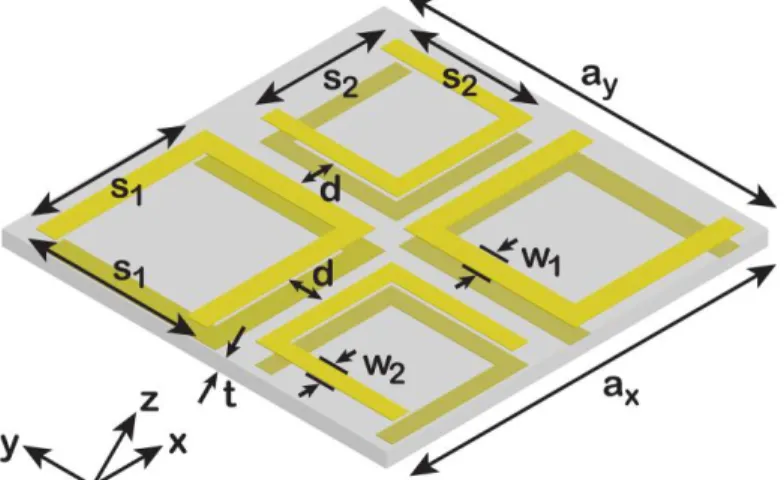
The unit cell of the proposed CMM structure is depicted in Fig. 1. It is an asymmetric version of the structure that has been studied in Refs. 19,21,35. In a previous study, it has been demonstrated that a similar variant of this design operates as a circular polarizer for incident waves that are linearly polarized in the x-direction [24]. For the circular polarizer, the coupling between the meta-atoms has been optimized in order to provide maximum wave
ellipticity in the vicinity of the resonance frequencies as to ensure that the transmitted wave is circularly polarized. Conversely, the design goal in this study is minimizing the transmitted wave ellipticity as to rotate a linearly polarized incident wave without distorting the linearity of the polarization.
Fig. 1. Geometry of the simulated and fabricated chiral metamaterial unit cell.
The following geometrical parameters for the unit cell are used in the simulations and experiments: ax = ay = 13.6 mm, s1 = 6 mm, s2 = 4.8 mm, w1 = 0.7 mm, w2 = 0.55 mm, d = 1.4
mm, and t = 1.5 mm. A FR-4 board with a relative permittivity of 4 and a dielectric loss tangent of 0.025 is utilized as the substrate. For the metallic parts, copper that is 30 µm thick is used. As it will be presented subsequently, the operating frequency of the CMM is 6.2 GHz. At this frequency, the structure is electrically thin with t / λ 0.031. In addition, the periodicity in the transverse plane is electrically small at 6.2 GHz, since ax = ay corresponds to 0.281λ.
3. Numerical Results
We initiated the analysis with numerical simulations of the proposed CMM unit cell using CST Microwave Studio (Computer Simulation Technology AG, Germany), which is a commercially available software that utilizes the finite integration method. During the simulations, boundary conditions along the x and y directions are adjusted to be periodic in order to obtain periodicity in the transverse plane. The boundary condition along the z direction is selected to be absorbing. In order to characterize the response of the CMM, the structure is illuminated by plane waves propagating in the –z direction. Assuming the linearity of the CMM, linear transmission coefficients Txx and Tyx are obtained from the simulations
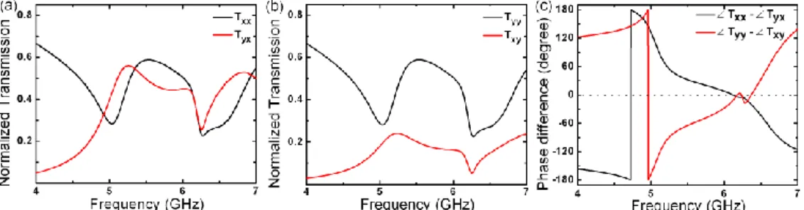
when the incident wave is x-polarized. Similarly, for a y-polarized incident wave, linear transmission coefficients Txy and Tyy are obtained. The magnitudes of the four linear
transmission coefficients are shown in Fig. 2(a) and 2(b). The mutual phase differences between Txx and Tyx, and Tyy and Txy are shown in Fig. 2(c).
Using Fig. 2, it is observed that the CMM creates an electric field that is orthogonal to the incident field, since the cross-coupling terms Txy and Tyx are non-zero. In addition, the
simulation results reveal that Txx and Tyy are equal in terms of magnitude and phase (phase not
shown here). In other words, the transmitted x-polarization due to an x-polarized incidence is equal in terms of magnitude and phase to the transmitted y-polarization due to a y-polarized incidence. Conversely, it is noticed that the transmitted y-polarization due to an x-polarized incidence is strongly different than the transmission of the x-polarization due to a y-polarized incidence. Using these observations, it can be deduced that this CMM configuration creates polarization angle dependent chirality.
Fig. 2. Magnitudes of the linear transmission coefficients when the CMM is illuminated by (a) x-polarized and (b) y-polarized incident waves. (c) The mutual phase differences between the transmission coefficients.
The asymmetric transmission of the structure is also explicable using the linear transmission coefficients. Due to the geometry, illuminating the structure by a plane wave polarized in the y-direction and propagating in the –z direction is equivalent to illumination by a plane wave polarized in the x-direction and propagating in the + z direction. The two waves encounter the same transmission coefficients with respect to their polarization direction, e.g.,
Txx becomes Tyy and Tyx becomes Txy. Thus, the transmission of the CMM is asymmetric.
Figure 2(c) shows the mutual phase differences between Txx and Tyx, and Tyy and Txy. At 6.2
GHz, which is the operating frequency of the device, the mutual phase differences are approximately equal to 0°, in turn demonstrating that at this frequency optical activity is observed. Although the mutual phase differences are 0°, the phases of all the elements must be equal in order to avoid the transmission of elliptically polarized wave. We investigated the numerical results and observed that at 6.2 GHz, the phases of all linear transmission coefficients are equalized. As a result, combining the two orthogonal cases, linearly polarized waves are eigenwaves of the CMM at 6.2 GHz and are transmitted with a polarization rotation.
Thereafter, circular transformation coefficients [24] are calculated using and
x xx yx y yy xy
C T iT C T iT (1)
for the two separate incident polarizations. In order to characterize the polarization of the transmitted wave, the polarization azimuth rotation angle θ is calculated using the formula
,
,, arg x y arg x y
x y C C
(2)
and the ellipticity of the transmitted wave, which is defined as
, , , , , arctan x y x y x y x y x y C C C C (3)
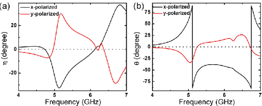
is determined. The results retrieved from the simulations for the polarization rotations and the transmitted wave ellipticities are shown in Fig. 3. In Fig. 3(a), it is observed that the ellipticities of the transmitted waves for x-polarized and y-polarized incident fields are approximately equal to zero at 6.2 GHz, which corresponds to pure optical activity at this frequency. The corresponding azimuth polarization rotation angles for x-polarized and y-polarized incident fields are shown in Fig. 3(b).
According to the results given in Fig. 3, an incident wave that is linearly polarized in the x direction is rotated by 46° at 6.2 GHz, whereas a y-polarized incident wave is rotated by 15° at the same frequency. Due to different rotations for x and y polarizations, each incident polarization angle encounters a different rotation. The relationship between the incident polarization angle and the resulting polarization rotation can be derived by performing simple geometrical calculations based on the rotation values provided above. However, for
simplicity, we will employ the transfer matrix formulation subsequently for determining this relation.
Fig. 3. (a) Ellipticities and (b) polarization azimuth rotation angles of the transmitted waves for x-polarized and y-polarized illumination.
4. Experiment Results
In order to characterize the behavior of the CMM and examine the validity of the simulation results, we performed experiments. We fabricated the structure with a dimension of 16 by 16 unit cells. The experiment is conducted using two standard horn antennas facing each other at a 60 cm distance. The structure is placed in the middle between the antennas. The transmission coefficients are measured using an HP-8510C network analyzer (Agilent Technologies, USA).
Fig. 4. (a) Experimental magnitudes of Txx and Tyx, and (b) Txy and Tyy. (c) Mutual phase differences obtained from the experiments.
The x and y components of the transmitted fields due to x and y polarized incident waves are measured for characterization. Phase information is also obtained from the network analyzer in order to calculate the rotation and ellipticity for the transmitted waves. The experimental magnitudes of Txx, Txy, Tyx and Tyy are shown in Fig. 4, as well as the phase
differences between Txx and Tyx, and Tyy and Txy. In Fig. 2(c), the phase differences are
approximately equal to 0° at 6.2GHz. For the experiment results, at 6.2 GHz we obtain 6° for the phase difference between Txx and Tyx and 7° for the Tyy and Txy case. Throughout the
scanned frequency range, the experiment results agree closely with the simulations.
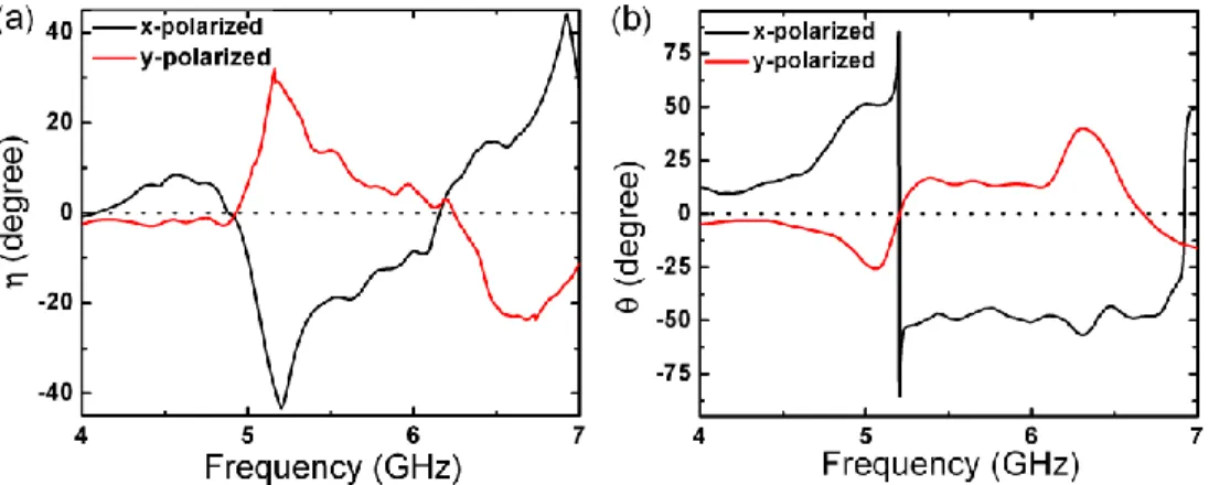
In addition to the transmission results, we extracted the ellipticity and polarization rotation information from the measurement data. These results are shown in Fig. 5, which is the experimental analog of Fig. 3. At 6.2 GHz, the ellipticity of a transmitted wave due to an x-polarized incidence is 4.2°. Similarly, for a y-x-polarized incident wave, the ellipticity of the transmitted wave is 2.9°. These results are very close to the numerical results, where both ellipticities are approximately equal to 0°. Subsequently, we examine the experimental results for polarization rotation. Experiment results indicate that the amount of rotation is 49° for an
x-polarized incident wave at 6.2 GHz. This value differs by 3° from the simulation results,
which indicates a good agreement. However, we obtain a 26° rotation for a y-polarized wave at the same frequency. Numerical results provided 15° rotation for a y-polarized field, which differs by 11° from the experiment result. These discrepancies can be attributed to the inaccuracies in the fabrication stage, multi-reflections in the experiment setup, diffraction effects from the sharp edges of the CMM structure, probable misalignments and non-zero cross-polarization response of the antennas. In addition, the resonance frequencies slightly shift to higher frequencies in the experiments. The possible reasons are the variance of the dielectric permittivity of the FR-4, experiment inaccuracies and simulation inaccuracies, i.e., mesh size affects the resonance frequencies. Overall, we conclude that the agreement between the numerical and experiment results is good and the operation of the CMM is verified experimentally.
Fig. 5. (a) Experimental ellipticies and (b) polarization rotations of the transmitted waves due to x and y-polarized incident waves at 6.2 GHz.
5. Formulation
Assuming that the CMM structure is a two-input and two-output system, where the fields associated with the x and y directions represent the two inputs and the two outputs of the system, a transmission matrix T, with the elements Txx, Txy, Tyx and Tyy can be defined so that
the following relation holds
0 0 , xd xx xy x yx yy yd y E T T E T T E E (4)
where Exd and Eyd are the transmitted fields along the x and y directions, respectively.
Similarly, Ex0 and Ey0 represent the electric field components of the incident field along the x
and y directions. In linear equation form, Eq. (4) can be rewritten as the follows:
0 0 0 0. xd xx x xy y yd yx x yy y E T E T E E T E T E (5)
Subsequent to the calculation of transmitted x and y components for an arbitrary input to the system, the polarization angle of the transmitted wave is calculated as
0 0 1 0 0 tan yx x yy y . xx x xy y T E T E T E T E (6)
In order to relate the transmitted polarization angle to the incident polarization angle, without loss of generality, we assume that the magnitude of the incoming wave is unity in all cases. Under this assumption, Eq. (6) is modified as
1 cos sin tan , cos sin yx yy xx xy T T T T (7)
where φ denotes the polarization angle of the incident wave. It is noteworthy that the inverse tangent is a multi-valued function that requires special attention. The quadrant where lies depends on the signs of the numerator and denominator of Eq. (7). Finally, the corresponding polarization rotation is defined as
.
(8)Then, to calculate the polarization rotation introduced by the CMM at 6.2 GHz, we constructed the transmission matrices using the simulation results for waves propagating in the –z and + z directions. Thereby, the asymmetric transmission of the design would be demonstrated simultaneously with the incident polarization angle dependent polarization rotation. For an incident wave propagating in the –z direction, the elements of the transmission matrix are given as Txx = 0.3568, Txy = 0.1104, Tyx = 0.3599 and Tyy = 0.3568. In
general, these elements are complex quantities carrying phase information. However, in this case we omit the phases of the elements, since the simulation and experiment results prove that all the elements are in-phase. Thus, using only the magnitude information is sufficient. Similarly, for a + z propagating wave, the transmission matrix elements are given as Txx =
0.3568, Txy = 0.3599, Tyx = 0.1104 and Tyy = 0.3568. The two transmission matrices
demonstrate the asymmetric transmission of the structure, since Txy and Tyx values are not
equal for the + z and –z cases. Figure 6(a) shows the calculated polarization angle of the transmitted wave, using Eq. (7), due to incident waves linearly polarized from 0° to 360° and propagating in the – z and + z directions. The corresponding polarization rotation calculated using Eq. (8) is presented in Fig. 6(b).
Fig. 6. (a) Polarization angles of the transmitted linearly polarized waves with respect to the polarization angle of the incident wave, at 6.2 GHz, for the –z and + z propagating waves (b) Introduced polarization rotation to the –z and + z propagating waves with respect to the incident polarization angle, at 6.2 GHz.
As it is apparent in Fig. 6(a), at several angles, -z and + z propagating waves are transmitted symmetrically, with the same polarization. Equating given by Eq. (7) for the above-mentioned transmission matrices, we obtain the following transcendental equation to calculate these angles:
1 0.3599 cos 0.3568sin 1 0.1104 cos 0.3568sin
tan tan .
0.3568cos 0.1104sin 0.3568cos 0.3599sin
(9)
Numerical solution for Eq. (9) yields φ = 35.3°, 125.3°, 215.3° and 305.3°. Figure 6(b) presents θ as a function of , which is calculated using Eqs. (7) and 8.
It is seen that the proposed CMM is reciprocal, i.e., it shows the same θ for the waves propagating in the –z and + z directions, which are linearly polarized at the angles those are being equal to the solutions of Eq. (9). In turn, for polarization angles, which do not satisfy Eq. (9), the transmission is asymmetric, i.e., different for waves propagating in the –z and + z directions. In both cases, linearly polarized waves are eigenwaves for both directions.
6. Surface Currents
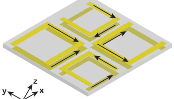
In order to explain the asymmetric transmission, we investigated the induced surface currents at 6.2 GHz, when the CMM is excited by x-polarized waves propagating in the –z and + z directions. The simulation results indicate that the directions of the induced surface currents are identical for both excitations. The directions of the surface currents are shown in Fig. 7.
Fig. 7. Directions of the induced surface currents due to x-polarized plane waves propagating in the –z and + z directions at 6.2 GHz.
As the next step, we have simulated a single SRR pair, where one SRR is rotated by 90° with respect to the other. We observed that coupling from the x-polarization to the y-polarization decreases when the electric field vector of the incident wave is parallel to the slit of the SRR that is closer to the source. However, rotating the pair by 90°, while keeping the electric field vector direction constant, does not change the transmission of the x-polarization. In the case where each SRR pair has the same dimensions, rotation does not affect the transmission coefficients. In the asymmetric case, rotation decreases coupling from x-polarization to y-x-polarization, whereas the transmission of the x-x-polarization is not changed. When the structure is rotated, smaller SRR pairs are not at the resonance since their resonance frequencies are larger. In addition, according to the simulation results, larger SRR pairs begin to produce less y-polarization compared to the previous case. Thus, illuminating the structure by an x-polarized wave is not equivalent to illumination by a y-polarized wave. It should also be denoted that due to the geometry of the CMM, illuminating the structure by a y-polarized wave propagating in the –z direction is equivalent to illuminating it by an x-polarized wave propagating in the + z direction. Hence, as a result of different transmission coefficients for the x and y polarized waves, the transmission of the structure is asymmetric.
7. Conclusion
In conclusion, we have designed an electrically thin CMM structure that allows obtaining polarization rotation, which is dependent on the polarization angle of the incident linearly polarized plane wave at 6.2 GHz. We derived a closed form expression, which relate the
degree of polarization rotation to the polarization angle of the incident wave. In addition, it has been demonstrated that the transmission matrix, T, depends on the propagation direction of the incoming wave. Thus, the transmission through the structure is asymmetric for linearly polarized waves. On the other hand, four angles have been found for which the transmission is symmetric. Finally, surface current distributions at 6.2 GHz are studied in order to explain the underlying mechanism behind the asymmetric transmission. The CMM can be utilized in microwave applications as a configurable polarization rotator. The ideas of the suggested design can be adapted in future research for terahertz and optical applications.
Acknowledgments
This work is supported by the European Union (EU) under the projects PHOME, ECONAM, and N4E; by The Scientific and Technological Research Council of Turkey (TUBITAK) under the projects 109E301, 107A004, and 107A012; and the State Planning Organization (DPT) under the project DPT-HAMIT. One of the authors (E. Ozbay) also acknowledges partial support from the Turkish Academy of Sciences.