Absorption enhancement in
InGaN-based photonic crystal-implemented
solar cells
Tamara Funda Gundogdu
Mutlu Gökkavas
crystal-implemented solar cells
Tamara Funda Gundogdu, Mutlu Gökkavas, and Ekmel Ozbay
Bilkent University, Nanotechnology Research Center—NANOTAM, Bilkent,06800 Ankara, Turkey
Abstract.We investigate the absorption characteristics of InGaN solar cells with high indium (0.8) content and a one-dimensional periodic nano-scale pattern (implemented) in the InGaN layer theoretically. The short-circuit current of our InGaN-based solar cell structure is calculated for different lattice constant, etch depth, and fill factor values. A substantial increase in the absorption (17.5% increase in short-circuit current) is achieved when the photonic crystal pattern is thoroughly optimized.© 2012 Society of Photo-Optical Instrumentation Engineers (SPIE). [DOI:10 .1117/1.JNP.6.061603]
Keywords:InGaN; solar cell; photonic crystal; absorption enhancement.
Paper 12032SS received Apr. 4, 2012; revised manuscript received Jul. 5, 2012; accepted for publication Jul. 5, 2012; published online Jul. 26, 2012.
1 Introduction
With the ever-growing need for energy and the limited nature of fossil-based energy resources, scientists have been intensively concentrating on the utilization of renewable energy. Solar cell technologies, with their ability to produce electricity due to the photovoltaic effect, are foreseen as strong candidates for the renewable energy solution. So far, photovoltaics, mostly based on silicon, GaAs, and other semiconductor compound multijunctions, have been widely used in order to realize high-performance photovoltaics.1These materials, with relatively small band gaps, are limited in their photovoltaic efficiency due to problems with effective surface absorp-tion and excess carrier energy generaabsorp-tion when harvesting the high energy porabsorp-tion of the solar irradiation.
After the recent discovery of group III-nitride InGaN compounds having their bandgap tun-able from 0.7 to 3.7 eV,2,3InGaN/GaN4heterostructures have gained much attention for solar cell applications because of the potential of broad spectral absorption, relatively easier multi-junction fabrication (single material system), high absorption coefficient allowing for thinner epitaxial layers, and mature fabrication knowledge based on light-emitting diodes5and high carrier mobi-lity.6In addition, InGaN is considered for applications in space owing to its superior radiation resistance.7To date, the indium concentration of InGaN alloys used in successfully fabricated InGaN/GaN solar cells remained low,8limiting effective absorption to a small spectral range. When the indium content of InGaN is increased (for example, to >25%) to cover a larger spectral range, the InGaN critical thickness (approx. 30 nm) becomes the limiting factor.9
Over the last decade, with the development of ever more enabling fabrication technologies, subwavelength structures such as metamaterials10,11and plasmonic devices12have been widely studied at photonic wavelengths. Specifically, nanophotonic methods may be employed to enhance the absorption in a thin absorbing layer of active material.13There have been reports on several solar cell designs utilizing subwavelength geometries14 such as surface nano-patterns,15,16 backside gratings,17,18 plasmonic nanostructures,19,20 embedded nanoparticles,21 and nanowires.22–24 These structures mostly aim at the excitation of guided mode resonances within thin active layers in order to increase absorption. Recently, reports on InGaN-based nano-photonic solar cells have appeared in the literature as well. In one study, Ag nanoparticles were used on an InGaN quantum well photovoltaic device to demonstrate a 54% external quantum
efficiency increase.25In another study, embedded plasmonic nanoparticles have been proposed, and numerical results up to 27% efficiency enhancement were presented.26From the material growth and device fabrication perspective, nanostructures contained to the surface are techno-logically more feasible compared with embedded particles such as in Ref.26. Photonic crystal structured surfaces have been proposed and studied to increase the enhancement of absorption in thin film solar cells by way of light trapping, optical path increase, and impedance matching.27
These studies have mostly been limited to silicon with one exception of a Ge solar cell.28 In this study, we propose a design where a one-dimensional (1-D) photonic crystal structure is implemented within the InGaN/GaN material system in order to demonstrate an absorption enhancement for a thin InGaN layer. For this purpose, the absorption spectra of the proposed design are calculated, and the dependence of the short-circuit current density on the geometrical parameters of the design is investigated.
2 Structure and Method
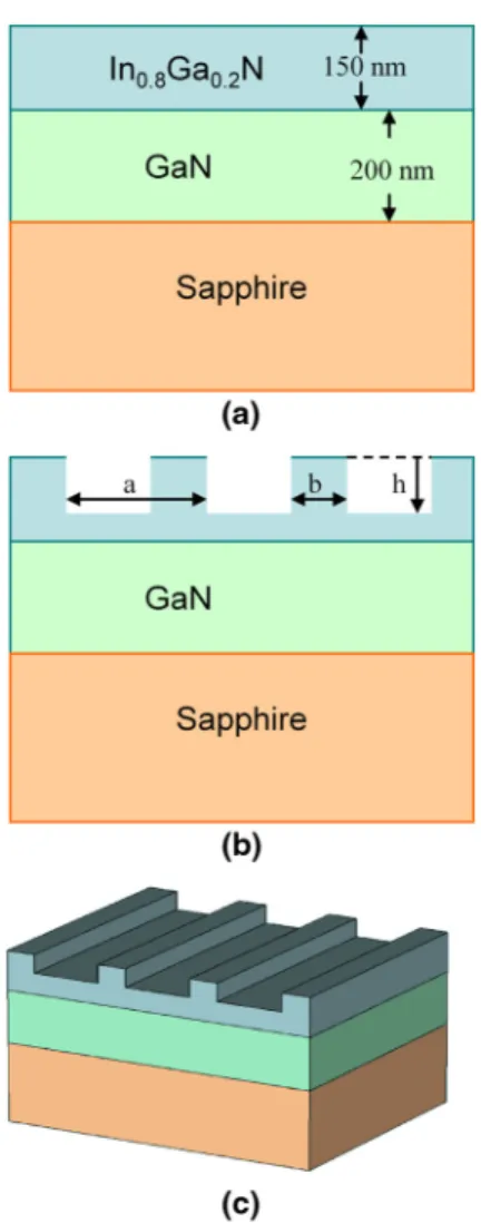
The studied layer structure is shown in Fig.1(a). An In0.8Ga0.2N layer with a thickness of 150 nm grown on top of a 200-nm-thick GaN layer is considered as the basis of the study. Conventional sapphire substrate is also included in the calculations. The cross section of the fabricated photo-nic crystal pattern is shown in Fig.1(b). For the fabrication of the nanoscale pattern, the top surface of the InGaN layer is etched to a depth described by the parameter h, in the form of a 1-D periodic pattern that has a period denoted by the parameter a. The length of the unetched
Fig. 1 (a) Studied InGaN structure; (b) cross-sectional etch geometry; (c) 3-D view.
region is labeled by the parameter b. The drawing in Fig.1(c)shows the three-dimensional (3-D) depiction of the structure under investigation.
It is adequate to use the current-voltage curve to describe the electrical characteristics of a solar cell. Most importantly, it is possible to determine the efficiency of a solar cell from the I-V curve. In the theoretical analysis of a single junction solar cell, it is customary to model the solar cell as an ideal diode where the generation rate has an additional component due to the incident illumination. By using the expressions for the I-V characteristics reported in Ref.29, it can be shown there is an approximately linear relation between the short-circuit current density jscand solar cell efficiency. Therefore, it is appropriate to use the short-circuit current density as an electrical figure of merit without going into further detail of the electrical behavior of the cell. With the assumption that every electron-hole pair generated is delivered to the external circuit, neglecting the effect of the pattern on the electrical properties of the cell, the short-circuit current density is given by
jsc¼ Z djsc dλ dλ ¼ e Z AðλÞdN dλdλ: (1)
Here AðλÞ indicates the absorption spectrum; that is, the probability that a photon with wave-lengthλ incident on the cell is absorbed by the cell. dN∕dλ is the number of photons incident on the cell per unit area and time; that is, the photon flux between the wavelength rangeλ þ dλ. The limits of the integral are determined by the wavelength regime of interest (spectrum of incoming light). For the case of terrestrial solar applications, the lower limit of the integral is 280 nm, since below this wavelength the ozone layer acts as an ultraviolet (UV) block. The upper limit of the integral depends on the absorber material. In the case of our In0.8Ga0.2N layer, this value is 860 nm. Therefore, for any given structure, first the absorption spectrum is calculated and then it is weighted by the spectral number of incoming photons and integrated to find the short-circuit current density. For the calculations, we used the spectrum of a blackbody radiator at 5800 K normalized to 1000 W∕m2. This is preferred over the AM 1.5G spectrum owing to its smoothness.
For the calculation of the absorption spectrum, we used the finite-difference time-domain (FDTD) method through the commercial software Lumerical. Periodic boundary conditions were applied along the lateral direction. For normal incidence, reflected and transmitted powers through the structure and absorbed power in the InGaN layer were calculated. The accuracy of results was confirmed through convergence tests. The wavelength-dependent refractive index of GaN was taken from Refs.30and31. The bandgap energy and real part of the refractive index for the InGaN layer was taken from Refs.32and33. The imaginary part of the refractive index for the InGaN layer was modeled after GaN, taking into account the appropriate energy shift.
3 Results
Several simulations were performed in order to optimize the photonic crystal pattern implemen-ted within our InGaN based solar cell structure. For this purpose, the parameter space spanned by the three parameters a (period), h (etch depth), and fill factor ðFFÞð¼ b∕aÞ was investigated, and the short-circuit current density was chosen as the figure of merit to optimize. It was observed that the highest short-circuit current density was obtained when the period a ¼ 300 nm. Slightly larger and smaller values for the period yielded qualitatively similar parametric dependence, with nevertheless lower values for the short-circuit current.
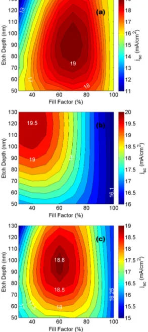
Examples of these results of the parametric calculations are shown in Figs.2and3for a ¼ 300 nm and a ¼ 400 nm, respectively. In each figure, part (a) shows the short-circuit current density when incident light is polarized perpendicular to the periodic pattern. Similarly, part (b) is for the case when incident light is polarized parallel to the periodic pattern. Finally, part (c) of each figure shows the short-circuit current density for unpolarized light at normal incidence. In each part of Figs.2and3, the horizontal axis (fill factor), and the vertical axis (etch depth) span a two-dimensional (2-D) parameter space. By the examination of the figures, it is evident that the maxima occur at (FF ¼ 70%, h ¼ 90 nm) for perpendicular polarization, at (FF ¼ 40%, h ¼ 120 nm) for parallel polarization, and at (FF ¼ 60%, h ¼ 100 nm) for no polarization, in
the case of a ¼ 300 nm. In comparison, the maxima occur at (FF ¼ 80%, h ¼ 90 nm) for perpendicular polarization, at (FF ¼ 50%, h ¼ 130 nm) for parallel polarization, and at (FF ¼ 60%, h ¼ 110 nm) for no polarization, in the case of a ¼ 400 nm.
The qualitative behavior of the parametric dependency trends around the optimum period of 300 nm can be observed in both Figs.2and3. First, the maximum enhancements occur at dif-ferent fill factor and etch depth values for the two orthogonal polarizations. It is observed that the perpendicular polarization absorption is enhanced at larger fill factors and lower etch depths compared with the parallel polarization. Second, the maxima occur at larger fill factors and etch depths for larger periods. In each figure, the right side of the figure corresponds to a 100% fill factor, which is a reference structure without any pattern. For unpolarized light, it is seen that the calculated short-circuit current density is 16 mA∕cm2for the reference structure, 18.8 mA∕cm2(which corresponds to a 17.5% enhancement over the reference structure) for the optimum geometry with a 300 nm period and 18.3 mA∕cm2for the optimum geometry with a 400 nm period.
Fig. 2 Calculated short-circuit current density for a ¼ 300 nm as a function of the fill factor and etch depth. The incident light is (a) perpendicular and (b) parallel to the photonic pattern. (c) For unpolarized illumination.
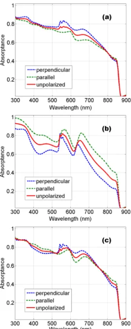
The polarization dependence for the a ¼ 300 nm structure can also be observed in the absorption spectra shown in Fig.4. Figure4(a)is the calculated absorption spectra for perpen-dicular polarized, parallel polarized, and unpolarized normal incident illumination at the opti-mum geometry (FF ¼ 70%, h ¼ 90 nm) for the enhancement of the perpendicular polarization. Similarly, in Fig. 4(b), the situation is depicted for the optimum geometry (FF ¼ 40%, h ¼ 120 nm) for the parallel polarization. Finally, Fig. 4(c) is the corresponding figure for the geometry (FF ¼ 60%, h ¼ 100 nm) that is optimum for unpolarized light. It is observed that, for all three parts of Fig. 4, the qualitative shape of the absorption spectra is similar with two distinctly realizable high absorption regions between 500 to 600 nm and 600 to 700 nm. A simple explanation often found in literature relates the nanophotonic pattern studied in our manuscript to a diffraction grating, which diffracts the normally incident light to oblique directions, increasing the optical path and absorption. However, since we are dealing with a nanophotonic pattern, ray optics is not applicable, and the role of the grating can be envisioned as coupling incident radiation to guided slab modes. The opening of diffraction channels
Fig. 3 Calculated short-circuit current density for a ¼ 400 nm as a function of the fill factor and etch depth. The incident light is (a) perpendicular and (b) parallel to the photonic pattern. (c) For unpolarized illumination.
together with Fabry-Perot resonances between the structure layers result in the complicated spec-tral absorption. As the etching depth is increased [as in Fig.4(b)], the slab modes are modified. This situation is referred in the literature as photonic crystal slab, where the incident radiation excites photonic crystal modes resulting in more pronounced peaks.
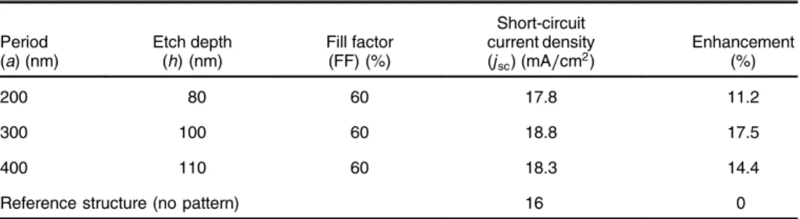
The absorption spectra for the reference not-etched structure and the optimum (for unpolar-ized light) 200-, 300-, and 400-nm period geometries are plotted in Fig.5for unpolarized, nor-mal incident light. It is observed that the structure with a 200-nm period allows for a smooth enhancement over a broad spectral range. Comparing the results of 300- and 400-nm periods, we observe that, as the period increases, the position of spectral absorption peaks shift toward longer wavelengths in accordance with the shifting of diffraction channels and photonic crystal modes. The geometric parameters and calculated short-circuit density for the four curves in Fig.5are listed in Table 1.
Fig. 4 Calculated absorptance spectra for normal incidence and when the incident light is polarized perpendicular to the photonic pattern (blue dashed), polarized parallel to the photonic pattern (green dot-dashed) and unpolarized (solid red). (a) Optimized for perpendicular polariza-tion. FF¼ 70%. h ¼ 90 nm. (b) Optimized for parallel polarization. FF ¼ 40%, h ¼ 120 nm. (c) Optimized for unpolarized incident light. FF¼ 60%. h ¼ 100 nm. Period a ¼ 300 nm.
In conclusion, we calculated the absorption spectra and the short-circuit current density for an InGaN-based solar cell with a nanophotonic periodic pattern and demonstrated that it is possible to enhance the short-circuit current up to 17.5% for unpolarized light. It is noteworthy to mention that this enhancement was obtained even though a significant fraction of the absorbing material was removed in order to realize the photonic pattern. It is possible to further increase the enhancement by the incorporation of a sacrificial layer on top of the InGaN layer and utilizing this layer for manufacturing the trenches instead of InGaN. The inclusion of antireflective coat-ings and backside reflectors would further increase the enhancement. With the advent of InGaN growth and fabrication technologies that are suitable for solar cell applications, the nanophotonic patterning of the surface can be employed to demonstrate working devices with efficiency enhancement.
Acknowledgments
This work is supported by the projects State Planning Organization (DPT-HAMIT), European Science Foundation (ESF-EPIGRAT), European Union (EU-N4E), and NATO-SET-181, and The Scientific and Technological Research Council of Turkey (TUBITAK) under the Project Nos. 107A004, 107A012, and 109E301. One of the authors (E.O.) also acknowledges partial support from the Turkish Academy of Sciences.
References
1. J. Nelson, The Physics of Solar Cells, Imperial College Press, London (2003).
2. J. Wu et al., “Small band gap bowing in In1-xGaxN alloys,” Appl. Phys. Lett. 80(25), 4741–4743 (2002), http://dx.doi.org/10.1063/1.1489481.
Fig. 5 Calculated absorptance spectra for unpolarized illumination. The different curves are for (light-blue dashed) reference structure without the surface pattern, (dark blue dotted) optimized pattern whena ¼ 200 nm, (solid green) optimized pattern when a ¼ 300 nm, (red dot-dashed) optimized pattern whena ¼ 400 nm.
Table 1 Geometric parameters and calculated short-circuit for the spectra in Fig.5.
Period (a) (nm) Etch depth (h) (nm) Fill factor (FF) (%) Short-circuit current density (jsc) (mA∕cm2) Enhancement (%) 200 80 60 17.8 11.2 300 100 60 18.8 17.5 400 110 60 18.3 14.4
3. T. Matsuoka et al., “Optical bandgap energy of wurtzite InN,” Appl. Phys. Lett. 81(7), 1246–1248 (2002), http://dx.doi.org/10.1063/1.1499753.
4. S. Korcak et al.,“Structural and optical properties of an In1-xGa1-xN∕GaN nanostructure,” Surf. Sci. 601(18), 3892–3897 (2007), http://dx.doi.org/10.1016/j.susc.2007.04.088. 5. B. Butun et al., “InGaN green light emitting diodes with deposited nanoparticles,”
Photon.Nanostruct. Fundament. Appl. 5(2–3), 86–90 (2007), http://dx.doi.org/10.1016/j .photonics.2007.07.005.
6. Y. Nanishi, Y. Saito, and T. Yamaguchi,“RF–molecular beam epitaxy growth and properties of inn and related alloys,” Jpn. J. Appl. Phys. 42(5A), 2549–2559 (2003),http://dx.doi.org/ 10.1143/JJAP.42.2549.
7. J. Wu et al.,“Superior radiation resistance of In1-xGaxN alloys: a full solar–spectrum photo-voltaic material system,” J. Appl. Phys. 94(10), 6477–6482 (2003), http://dx.doi.org/10 .1063/1.1618353.
8. O. Jani et al.,“Design and characterization of GaN/InGaN solar cells,” Appl. Phys. Lett. 91(13), 132117 (2007),http://dx.doi.org/10.1063/1.2793180.
9. C. A. Parker et al.,“Determination of the critical layer thickness in the InGaN/GaN hetero-structures,” Appl. Phys. Lett. 75(18), 2776–2778 (1999),http://dx.doi.org/10.1063/1.125146. 10. N. H. Shen et al.,“Optically implemented broadband blueshift switch in the terahertz regime,” Phys. Rev. Lett. 106(3), 037403 (2011),http://dx.doi.org/10.1103/PhysRevLett.106.037403. 11. T. F. Gundogdu et al.,“Simulation and micro–fabrication of optically switchable split ring resonators,” Photon. Nanostruct. Fundament. Appl. 5(2–3), 106–112 (2007),http://dx.doi .org/10.1016/j.photonics.2007.07.001.
12. E. Ozbay, “Plasmonics: merging photonics and electronics at nanoscale dimensions,” Science 311(5758), 189–193 (2006),http://dx.doi.org/10.1126/science.1114849.
13. S. Butun, N. A. Cinel, and E. Ozbay,“Nanoantenna coupled UV subwavelength photo-detectors based on GaN,” Opt. Express 20(3), 2649–2656 (2012), http://dx.doi.org/10 .1364/OE.20.002649.
14. C. Heine and R. H. Morf,“Submicrometer gratings for solar energy applications,” Appl. Opt. 34(14), 2476–2482 (1995), http://dx.doi.org/10.1364/AO.34.002476.
15. S. B. Mallick, M. Agrawal, and P. Peumans,“Optimal light trapping in ultra-thin photonic crystal crystalline silicon solar cells,” Opt. Express 18(6), 5691–5706 (2010),http://dx.doi .org/10.1364/OE.18.005691.
16. L. L. Yang, Y. M. Xuan, and J. J. Tan,“Efficient optical absorption in thin-film solar cells,” Opt. Express 19(S5), A1165–A1174 (2011),http://dx.doi.org/10.1364/OE.19.0A1165. 17. J. Gjessing, E. S. Marstein, and A. Sudbø,“2D back-side diffraction grating for improved
light trapping in thin silicon solar cells,” Opt. Express 18(6), 5481–5495 (2010),http://dx .doi.org/10.1364/OE.18.005481.
18. L. Zeng et al.,“Efficiency enhancement in Si solar cells by textured photonic crystal back reflector,” Appl. Phys. Lett. 89(11), 111111 (2006),http://dx.doi.org/10.1063/1.2349845. 19. K. R. Catchpole et al., “Plasmonics and nanophotonics for photovoltaics,” MRS Bull.
36(06), 461–467 (2011),http://dx.doi.org/10.1557/mrs.2011.132.
20. S. Pillai et al.,“Surface plasmon enhanced silicon solar cells,” J. Appl. Phys. 101(9), 093105 (2007),http://dx.doi.org/10.1063/1.2734885.
21. J. R. Nagel and M. A. Scarpulla,“Enhanced absorption in optically thin solar cells by scat-tering from embedded dielectric nanoparticles,” Opt. Express 18(13), A139–A146 (2010),
http://dx.doi.org/10.1364/OE.18.00A139.
22. E. Garnett and P. D. Yang,“Light trapping in silicon nanowire solar cells,” Nano Lett. 10(3), 1082–1087 (2010), http://dx.doi.org/10.1021/nl100161z.
23. J. Zhu et al.,“Optical absorption enhancement in amorphous silicon nanowire and nanocone arrays,” Nano Lett. 9(1), 279–282 (2009), http://dx.doi.org/10.1021/nl802886y.
24. L. Hu and G. Chen,“Analysis of optical absorption in silicon nanowire arrays for photo-voltaic applications,” Nano Lett. 7(11), 3249–3252 (2007), http://dx.doi.org/10.1021/ nl071018b.
25. I. M. Pryce et al., “Plasmonic nanoparticle enhanced photocurrent in GaN/InGaN/GaN quantum well solar cells,” Appl. Phys. Lett. 96(15), 153501 (2010), http://dx.doi.org/10 .1063/1.3377900.
26. J. Y. Wang et al.,“Enhancing InGaN-based solar cell efficiency through localized surface plasmon interaction by embedding Ag nanoparticles in the absorbing layer,” Opt. Express 18(3), 2682–2694 (2010),http://dx.doi.org/10.1364/OE.18.002682.
27. P. Bermel et al.,“Improving thin-film crystalline silicon solar cell efficiencies with photonic crystals,” Opt. Express 15(25), 16986–17000 (2007), http://dx.doi.org/10.1364/OE.15 .016986.
28. I. Prieto et al.,“Enhanced quantum efficiency of Ge solar cells by a two-dimensional photo-nic crystal nanostructured surface,” Appl. Phys. Lett. 94(19), 191102 (2009),http://dx.doi .org/10.1063/1.3133348.
29. C. Henry,“Limiting efficiencies of ideal single and multiple energy gap terrestrial solar cells,” J. Appl. Phys. 51(8), 4494–4500 (1980), http://dx.doi.org/10.1063/1.328272. 30. J. F. Muth et al.,“Absorption coefficient, energy gap, exciton binding energy, and
recom-bination lifetime of GaN obtained from transmission measurements,” Appl. Phys. Lett. 71(18), 2572–2574 (1997),http://dx.doi.org/10.1063/1.120191.
31. N. Watanabe, T. Kimoto, and J. Suda,“The temperature dependence of the refractive indices of GaN and AlN from room temperature up to 515 C,” J. Appl. Phys. 104(10), 106101 (2008),http://dx.doi.org/10.1063/1.3021148.
32. G. M. Laws et al.,“Improved refractive index formulas for the AlxGa1-xN and InxGa1-yN alloys,” J. Appl. Phys. 89(2), 1108–1115 (2001),http://dx.doi.org/10.1063/1.1320007. 33. M. Anani et al.,“InxGa1-yN refractive index calculations,” Microelectronl J. 38(2), 262–266
(2007),http://dx.doi.org/10.1016/j.mejo.2006.11.001.
Tamara Funda Gundogdu received BSc and MSc degrees in physics
from Yildiz Technical University, Istanbul, Turkey in 1998 and 2001, respectively. She received her PhD from University of Crete, Material Science and Technology Department. Her PhD thesis was on left-handed materials and composite metamaterials, and she studied under supervision of professor Costas Soukoulis. During her PhD she also worked as a researcher in Foundation for Research and Technology Hellas (FORTH) and as a teaching assistant in University of Crete. She joined professor Ekmel Ozbay’s group in Bilkent University, Nanotechnology Research Center (NANOTAM) as a post-doctoral research associate.
Mutlu Gokkavasreceived BSc and MSc degrees in electrical engineering from Bilkent University, Ankara, Turkey, and a PhD in electrical engineer-ing from Boston University in 1994, 1996, and 2002, respectively. Durengineer-ing his doctoral study and later as a senior scientist of Focused Research Inc., Madison, WI, he worked on design, characterization, and fabrication of high-speed photodetectors for optical telecommunications. He joined the Bilkent University Nanotechnology Research Center as a visiting assistant professor in 2004, where he is currently working on design, fabrication, and characterization of semiconductor optoelectronic and integrated optic devices.
Ekmel Ozbayreceived MS and PhD degrees from Stanford University in electrical engineering, in 1989 and 1992. He joined Bilkent University (Ankara, Turkey) in 1995, where he is currently a full professor in Depart-ment of Electrical-Electronics Engineering. His research in Bilkent involves nanophotonics, nanometamaterials, nanoelectronics, nanoplasmo-nics, nanodevices, photonic crystals, and GaN/AlGaN MOCVD growth. He is the 1997 recipient of the Adolph Lomb Medal of Optical Society of America and 2005 European Union Descartes Science award. He has published 295 articles in SCI journals. His papers have received 7400+ citations with an h-index of 42.