FOCUSED RF ABLATION
USING MAGNETIC FLUIDS
A THESIS
SUBMITTED TO THE DEPARTMENT OF ELECTRICAL AND
ELECTRONICS ENGINEERING
AND THE INSTITUTE OF ENGINEERING AND SCIENCE
OF BILKENT UNIVERSITY
IN PARTIAL FULFILLMENT OF THE REQUIREMENTS
FOR THE DEGREE OF
MASTER OF SCIENCE
By
T. Onur Taşcı
ABSTRACT
FOCUSED RF ABLATION
USING MAGNETIC FLUIDS
T.Onur Taşcı
M.S. in Electrical and Electronics Engineering Supervisor: Prof. Dr. Ergin Atalar
August, 2006
In most developed countries, cancer is presently responsible for about 25% of all deaths. Heat therapies like hyperthermia and thermoablation are very promising approaches in the treatment of the cancer. Since these are physical treatment methods they have fewer side affects compared to chemo- and radio-therapy. Currently, various types of heat treatment modalities are available like microwave, ultrasound, RF capacitance hyperthermia, RF probe hyperthermia, magnetic fluid hyperthermia, but non of these methods have the ability to accurately deliver high heat energy to deeply seated tumors without damaging the healthy surrounding tissues.
In this thesis, a novel RF ablation system was developed capable of focusing the heat in to very small areas in the order of millimeters, which will allow heating of the tumors without destroying collateral normal tissues. Generally, in this system
the tumor ablation is achieved via coupling RF energy on the magnetic fluids which are previously dispersed in to the tumor tissue.
By considering the human safety limits (nerve stimulation and tissue eddy current heating safeties) optimum treatment parameters like particle size of the magnetic fluids, frequency and strength of the applied RF field are obtained. The utilization of the optimum parameters may lead to the very effective operation of the ablation system where treatments can be done with very small amounts of fluid injections, in short durations.
We believe that by the studies conducted in this thesis, magnetic fluid hyperthermia (tumor ablations using magnetic fluids) can be a much more effective method so that it can be used as the one of the most important tumor treatment techniques in future.
Key words: Tumor Therapy, Hyperthermia, Thermo ablation, Magnetic Fluid
ÖZET
MANYETIK SIVI KULLANILARAK
YAPILAN ODAKLANMIŞ RADYO DALGA
ABLASYONU
T.Onur Taşcı
Elektrik Elektronik Mühendisliği, Yüksek Lisans Tez Yöneticisi: Prof. Dr. Ergin Atalar
Ağustos, 2006
Birçok gelişmiş ülkede, kanser, ölümlerin yüzde 25’ini oluşturmaktadir., Hipertermi ve termoablasyon gibi ısı terapileri, kanser tedavisinde büyük umut
vadetmektedirler. Bunlar, fiziksel tedavi yöntemleri oldukları için kemo ve radyoterapiye göre daha az yan etkiye sahiptirler. Hali hazırda, mikrodalga, ultrason, RF kapasitif hipertermi, RF prob hipertermi, manyetik sıvı hipertermisi gibi birçok ısı tedavi yöntemi bulunmakla birlikte, bunların hiçbiri derinlerde yerleşmiş tümörlere ısı enerjisini sağlıklı dokulara zarar vermeden verme kabiliyetine sahip değil.
Bu tezde, ısıyı çok küçük alanlara odaklayabilen, tümörleri, çevredeki normal dokulara zarar vermeden ısıtabilen, yeni bir RF ablasyon sistemi geliştirildi. Genel
olarak bu sistemde tumor ablasyonu, RF enerjisini, dokulara dağılmış manyetik sıvılara eşleyerek yapılıyor.
İnsan güvenlik sınırları dikkate alınarak, manyetik sıvı parçacık büyüklüğü, uygulanan RF dalgasinin ferekansı ve şiddeti gibi optimum tedavi parametreleri elde edildi. Bu optimum parametrelerin kullanımı, geliştirilen ısıtma sisteminin çok etkili çalışmasına yol açabilecek ve böylece çok az miktarda sıvı enjeksyonuyla çok kısa sürelerde tedaviler gerçekleşebilecektir.
Şuna inanıyoruz ki, bu tezde gerçekleştirilen çalışmalar sayesinde, manyetik sıvı hipertermisi (manyetik sıvı kullanılarak yapılan tümör ablasyonu) çok daha efektiv bir yöntem olacaktır ve ilerde en önemli tümör tedavi yöntemlerinden biri olarak kullanılacaktır.
Anahtar Kelimeler: Tümör terapisi, Hipertermi, Termo ablasyon, Manyetik Sıvı
Acknowledgements
I wish to express my deepest gratitude to my supervisor Prof. Ergin Atalar. He has not only been a supervisor to me with his vast knowledge, but also a perfect model both as a person and an outstanding academician in the field. During my M.S. study, I have got the taste of working in a wide range of research topics, which would be impossible without the guidance of Dr. Atalar. In my future academic life, I will always want to make research with him about many other exciting fields of biomedical engineering.
I would like to thank Dr. Anil Arat(MD) for introducing the topic of this thesis and helping me in many aspects of this research. My special thanks go to Dr. İbrahim Vargel without whom it was impossible to finish the in vivo experiments of this thesis. Also, I would like to thank Prof. Dr. Ayhan Altıntaş and Dr. Tarık Reyhan for their valuable discussions through out my M.S. study. I wish to thank Dr. Petek Korkusuz and Dr. Elif Güzel for the histological analysis and comments.
I would also thank to my dear friend Ahmet Serdar Tan, with whom my three years in Bilkent became more enjoyable than I expected. I am also grateful to my friends Rohat Melik and Serkan Onart, for their very encouraging and helpful attitude towards me.
Finally, I would like to thank to my parents Yüksel and Kazım Taşcı, and my dear sister Arzu Taşcı. Their presence was the biggest motivation to me in everyday of this study.
Table of Contents
1. Introduction ... 1
2. Optimization of MRI Contrast Agents for
Magnetic Fluid Hyperthermia Considering the
Human Safety Limits ... 3
2.1 Introduction ... 3
2.2 Methods ... 4
2.3 Results ... 8
2.4 Discussion and Conclusion ... 9
3. Focused RF Ablation Using Magnetic Fluids . 10
3.1 Introduction ... 10
3.2 Theory and Methods... 10
3.3 Experiments... 17
3.4 Results ... 20
3.5 Discussion... 27
3.6 Conclusion... 31
A. Design of Novel Catheter Detachment
Techniques...34
B. Electrical circuit modeling of the X-Ray
Photoelectron Spectrometer and the Sample
under consideration...51
C. Publications………..73
List of Figures
Figure 1. Hyperthermia applicator system………5
Figure 2. Endorem heating versus frequency………....6
Figure 3. Nerve stimulation and tissue eddy current heating safety graphs………..7
Figure 4. SAR(W/kg) of Endorem-like substance, as a function of particle radius and frequency……….8
Figure 5. Dependence of specific absorption rate of a gel sample (ferrite concentration 30 mg/ml) on the static magnetic field applied in the direction perpendicular to an AC field of 217 kHz and 9.6 kA/m………...12
Figure 6. Opposed solenoids produces a free region (FFR) in the middle of the solenoids………...14
Figure 7. General experimental setup used in the experiments………15
Figure 8. Matching circuit of the AC solenoid………..………...16
Figure 9. a) In vitro experiment setup, b) In vivo experiment setup………18
Figure10. Temperature versus time graphs of the in vitro experiments…………...20
Figure 11. a) Temperature curves of the three cups, b) Theoretical field strength plots………...23
Figure 12. Typical temperature versus time graph of the in vivo experiments……24
Figure 13. Rat Tail Photographs 24 hours after the hyperthermia application…….26
1. Introduction
Among the various types of heat therapy methods (microwave, ultrasound, radio frequency (RF) capacitance hyperthermia, magnetic fluid hyperthermia, RF probe hyperthermia etc.), magnetic fluid hyperthermia (MFH) gives better results in the treatment of deeply situated tumors with relatively good targeting [1]. In a general MFH treatment, firstly, magnetic fluids are dispersed in to target tissue and
secondly, by the application of AC magnetic fields, heating of the fluids and correspondingly damaging of the tumors is achieved [2]. But, as a result of the magnetic fluid diffusion from tumor to surrounding tissues or incorrect localization of the fluids in the target tumor area, unwanted heating of the healthy tissues can be seen. To overcome the normal tissue damage drawback of MFH, we proposed a novel focused ablation system which is capable of confining the heat energy in to very small regions which eliminates the risk of healthy tissue heating.
Our first study was on optimization of the hyperthermia parameters, like magnetic fluid particle size, RF field frequency and strength are done by considering the human safety limits (nerve stimulation and tissue eddy current heating). This work was presented in ISMRM conference and explained in detail in the second chapter. In the third chapter of this thesis, the theory behind the focused RF ablation
technique is explained in detail and very promising experimental results showing the successful operation of the ablation system is demonstrated.
study. In the first project, design and implementation of novel catheter detachment techniques were done and a provisional patent was filed. The details of this study are explained in Appendix A.
In the second project, electrical circuit modeling of the X-Ray photoelectron spectrometer and the sample under consideration was made. A manuscript explaining this work is almost ready to submit and presented in the Appendix B. Both works were presented in international conferences.
Finally, in Appendix C, a list of publications which is summarizing the work done during the M.S. study is shown.
2. Optimization of MRI Contrast Agents for
Magnetic Fluid Hyperthermia Considering the
Human Safety Limits
2.1 Introduction
Over the last decade, magnetic particle hyperthermia has been improved by the advent of “magnetic fluid hyperthermia” [2], where colloidal dispersions of superparamagnetic iron oxide nanoparticles (magnetic fluids) exhibit an
extraordinary specific absorption rate (SAR [W/g]) under the AC magnetic field. Moreover, these superparamagnetic particles provide contrast under MRI and their quantitative distribution can be obtained during an MRI scan. Much work has been done to find the optimum [2-3] treatment parameters (particle size, frequency, magnetic field strength, etc.) for hyperthermia, but none of these investigations has considered the human safety limits at the same time. In this work, we obtained the optimal hyperthermia parameters by considering human safety limits (nerve stimulation and tissue eddy current heating). The heating potential of the MRI contrast medium, Endorem™, was evaluated both theoretically and experimentally as a hyperthermia mediator.
2.2 Methods
The physical principles regarding the heating of superparamagnetic particles in AC magnetic fields have been reviewed by Rosensweig [4]. Basically, the power dissipation density (W/m3) for a monodispersion is given by equation below.
Where H0 is the magnetic field intensity, f is the frequency of the magnetic field; χ0 is the actual susceptibility, which is also a function of volume fraction of solids, domain magnetization of the suspended particle, and magnetic particle radius. τ is the effective relaxation time based on the Brownian and Néel relaxations, which is the function of the viscosity coefficient of the matrix fluid, the hydrodynamic volume of the magnetic particle, and the anisotropy constant. It is known that log normal particle distribution provides a reasonably good fit to the ferrofluid
distribution. Therefore, average power dissipation density ( P ) can be obtained for the lognormal distribution as below:
where g(R) is the log normal particle size distribution and R is the particle radius. Finally, the corresponding SAR (W/kg) value is found by:
(
3)
2 0 0 0 22
/
1 (2
)
f
P
H f
W m
f
π τ
πµ χ
π τ
=
+
0( )
P
=
∞∫
P g R dR
P
SAR
=
ρ
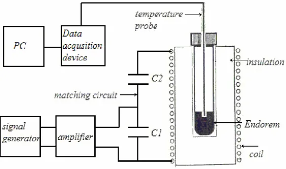
where ρ(kg/m3)is the density of the ferrofluid. For the verification of theoretical calculations, an in vitro hyperthermia experiment is made. A well-known MRI contrast agent, Endorem™, based on magnetite, was used as a hyperthermia mediator, which has a mean particle radius of 6nm and a lognormal size distribution with standard deviation of 3nm[3]. The experimental setup of the hyperthermia applicator system can be seen in Figure 1.
We applied an H0 of 3.1kA/m at various frequencies, ranging from 15 to 35 kHz.
SAR measurements were made with the rate of temperature rise method, such that the initial slope of the temperature versus time graph was multiplied with the specific heat capacity of Endorem™ according to the formula below.
Figure 1. Hyperthermia applicator system.
T SAR c t ∆ = × ∆
Both theoretical and experimental results are plotted in Figure 2 on the next page.
With the in vivo hyperthermia studies, a safety limit for the magnitude and frequency of the applied AC magnetic field was obtained. According to Reilly estimates [5], H0 should satisfy the inequality below so that no nerve stimulation would occur.
In addition, for tolerable eddy current heating of body tissues, the next inequality is proposed by Atkinson et al. [5].
Figure2. Endorem heating versus frequency. Dotted graph shows the
experimental results. Solid line is the result of theoretical calculations.
3 0 0 1 13.5 7.45 10 (A/m) f H µ − ⎛ ⎞ ≤ ⎜ + × ⎟ ⎝ ⎠ 8 0 4.85 10 (A/m) f H ≤ ×
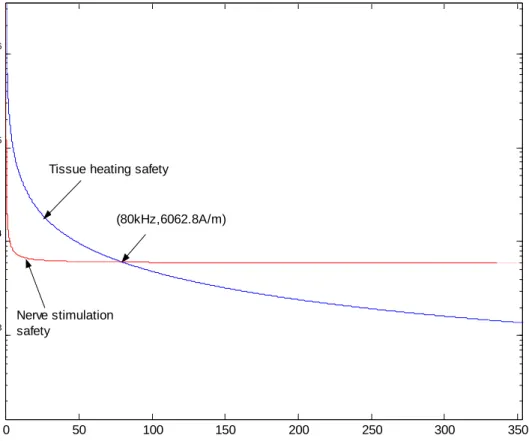
Both safety limits are plotted together in Figure 3 to obtain an overall safety limit for the applied magnetic fields. To satisfy both safety conditions, region under the two graphs should be taken.
To find the optimum parameters that yield the highest SAR value, we have calculated the SAR with respect to frequency and particle radius while staying below the overall safety limit. Figure 4 shows the resulting graph. The ferrofluid used in this calculation has the same physical properties as Endorem™ where magnetite has a volume fraction of %0.35 and an anisotropy constant of 23000 (J/m3), the fluid has a viscosity coefficient of 0.00235 (kg/ms) and a density of 1g/cm3.
Figure 3. Nerve stimulation and tissue eddy current heating safety graphs. 0 50 100 150 200 250 300 350 103 104 105 106 frequency(kHz) H0 (A /m )
Tissue heating safety
Nerve stimulation safety
2.3 Results
As can be seen from Figure 2, the experimental data closely matched the theoretical calculations, which demonstrated that theoretical heating calculations based on the work of Rosensweig[4] are suitable for actual predictions. Note also that Figure 2 shows that Endorem™ is far from being used as a hyperthermia mediator. Heat deposition of 100mW/ml of tissue is necessary for a successful hyperthermia
application. Again, looking at Figure 2 , to obtain a heating power of 100mW/ml by using Endorem™ at nearly 25kHz(where SAR ≈ 5mW/g), 20g of Endorem™ would be required for 1ml of tissue, which is physically impossible. Figure 4
Figure 4. SAR(W/kg) of Endorem-like substance, as a function of particle radius and frequency. Peak(584.6W/kg) occurs at the radius of
demonstrates that SAR results in a sharp peak at the particle radius of 7.25 nm and the frequency of 80 kHz;
i.e., magnetic fluid, which has the same physical properties of Endorem™ (with the same volume fraction of magnetite, the same anisotropy constant, the same
viscosity coefficient, and the same density, etc.) provides the maximum SAR for a monodisperse particle size of 7.25nm while staying within the safety limits. With this magnetic fluid, to obtain heat deposition of 100mW/ml of tissue, nearly 0.171g (of ferrofluid) could be enough for 1 ml of tissue, which demonstrates that, even with a very dilute magnetic fluid such as Endorem™ (where the magnetite volume fraction is 0.0035), the necessary heating rates can be achieved using very small portions of Endorem™, provided that optimum conditions are satisfied.
2.4 Discussion and Conclusion
Considering human safety limits, optimal hyperthermia parameters (H0, f, R) are
obtained for a magnetite-based ferrofluid with the physical properties of
Endorem™. With the optimal parameters, very small amounts of magnetic fluids, even with a low magnetite volume fraction (such as Endorem™) can be used successfully as a hyperthermia mediator. Future work should focus on obtaining very narrow magnetic particle size distributions to approach the optimal particle diameter dictated by the safety limits.
3. Focused RF Ablation Using Magnetic Fluids
3.1 Introduction
Heat treatments like hyperthermia and thermoablation are very promising
approaches in cancer therapy. Since these are physical treatment methods they have fewer side affects compared to chemo- and radio-therapy [1]. Currently, various types of heat treatment modalities are available like microwave, ultrasound, RF capacitance hyperthermia, RF probe hyperthermia, magnetic fluid hyperthermia etc. Each treatment technique has certain limitations [7, 8, 9, and 10]. For instance, microwave hyperthermia has a poor depth of penetration which is not suitable for treatment of deeply seated tumors. Compared to microwave, ultrasound has better penetration depth and focusing abilities. But particular drawbacks of ultrasound are high absorption of the bone and liquid containing organs, excessive reflection from the cavities filled with air and difficulties in determining the position of focus. In RF capacitance hyperthermia, the major limiting factor is the absence of electrical field focusing on the tumor, where all the tissues that the electric fields penetrate are heated. Finally, RF probe hyperthermia has the disadvantages of very hard
accessibility to the deep seated tumors, with a limited accuracy of localization. In addition, this technique is not suitable in the treatment of large tumors larger than 5 cm diameter.
Compared to the methods explained above magnetic fluid hyperthermia has better in uniform heating of the deeply situated tumors with relatively good targeting [7, 10]. In this technique, generally magnetic fluids are dispersed in to target tissue and by the application of AC magnetic fields heating of the fluids is achieved [2]. One
of the most important shortcomings of this technique is the unwanted heating of the healthy tissues. As a result of the diffusion of fluids from tumor to the collateral tissues, heating of the normal tissues can be seen. Some methods to selectively mark the tumors by magnetic particles have been proposed [11] but particle penetration to the surrounding healthy tissues hasn’t been prevented significantly. Since, dispersion of the magnetic particles to normal tissues currently unavoidable, a method to directly focus the heating on the tumors should be generated. In this study, we proposed and designed a system which focuses the heating in to very small regions so that focused heating of magnetic particles and accordingly tumors can be done without damaging any collateral healthy tissue. An analogical system for the tomographic imaging of the magnetic particles was demonstrated by Gleich and Weixenecker[12],
Operation principles of the proposed focused RF ablation system is explained briefly and successful operation of the system is verified via in vitro and in vivo experiments. Finally, experimental results are discussed and possible improvements on the system are stated.
3.2 Theory and Methods
It is well known that under alternating magnetic field, super-paramagnetic (single domain) nanoparticles are heated as a result of the rotation of the particle itself (Brownian relaxation) [13] and the rotation of the magnetic moment inside the particle ( Neel relaxation) [14]. In addition to the alternating field, if a static magnetic field is applied with equal or larger amplitude, the single domain particles and their magnetic moments align with the static field. Thus, Neel and Brownian relaxations are blocked and heating of the particles are diminished.
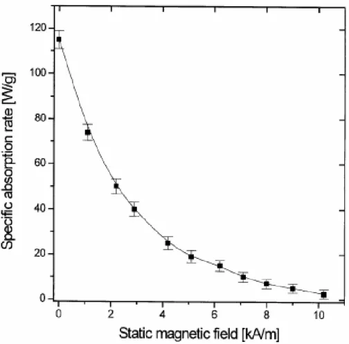
This fact is experimentally shown in previous studies [2, 6] where a static magnetic field perpendicular to AC field is applied to the ferrofluids (colloidal dispersions of superparamagnetic iron oxide particles) and it is observed that, heating is reduced significantly if the amplitude of the static field reaches to the strength of the
alternating field (Figure 5). These studies demonstrate us that static magnetic fields can be used to modulate the heating effect of AC magnetic fields on the magnetic domains.
Figure 5. Dependence of specific absorption rate of a gel sample (ferrite concentration 30 mg/ml) on the static magnetic field applied in the direction perpendicular to an AC field of 217 kHz and 9.6 kA/m. The results represent the mean ± SD from three independent
As mentioned earlier, in traditional Magnetic Fluid Hyperthermia systems,
magnetic particles which are dispersed in to the tissue are heated by application of AC magnetic fields. In this process unselective heating of the particles occurs where all the particles exposed to the alternating field are heated equally. Here, we show that by depositing appropriate DC magnetic field gradients on the AC magnetic fields one can generate AC field dominant regions and achieve focused heating of the magnetic particles at these regions. Figure 6 shows a system that accomplishes this task. Here two solenoids on the right and left of the figure are fed with equal but opposite DC currents. The static field vectors generated by the solenoids cancel each other at the center of the system and a region with a very small DC magnetic field is formed around the center which can be named as the field free region (FFR). If an alternating magnetic field is applied to the space between the solenoids,
alternating field will be dominant in the FFR and only the magnetic particles inside the FFR will be heated where as the particles outside this region can not be heated as a result of the dominance of the static field on the alternating field. The field free region explained above can be reduced further (i.e., more intense focus can be obtained) by increasing the current magnitudes flowing through the DC solenoids. In addition to that, the position of the focus can also be changed via giving different amplitudes of currents to the DC solenoids.
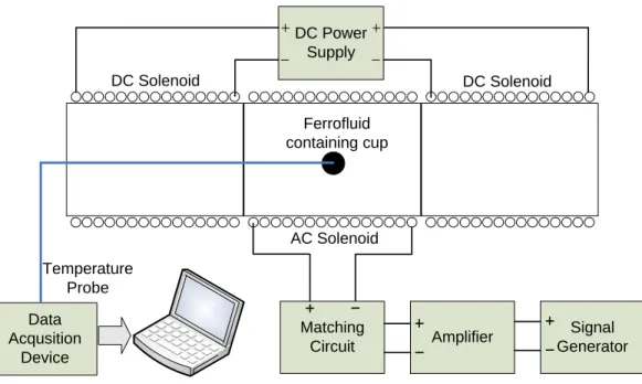
By adding one more solenoid between the lateral DC solenoids of Figure 6, implementation of focused heating applicator can be finished as in Figure 7. The solenoid in the middle (AC Solenoid) generates the alternating magnetic field which is responsible for the heating of the magnetic particles and other lateral solenoids (DC solenoids) generate a static magnetic field gradient such that a field free region is generated in the middle of them.
To test the explained focused heating system several in vitro and in vivo experiments were done by using the experimental setup shown in Figure 7.
Figure 6. Opposed solenoids produces a free region(FFR) in the middle of the solenoids. If an additional AC magnetic field is applied between the
solenoids only the particles in the FFR region will be heated and focused heating of the particles is achieved. (This figure is created by ViziMag 3.14 Software)
DC Solenoid DC Solenoid
Field Free Region
Air cored copper solenoids with equal sizes (coil length is equal to 6cm, inner and outer coil radius are 2 and 2.9cm respectively) were obtained from DAYM (Ders Aletleri Yapim Merkezi, Ankara, Turkey), where 1200 turn coils were used as the DC solenoids (35mH) and 300 turn coil was used as the AC solenoid (2.7mH). The copper thicknesses of the AC and DC solenoids were 1.3mm and 0.62mm
respectively, which are coiled on a bakelite material) A sinusoidal voltage obtained from the signal generator (Stanford Research Systems, DS345) was given to the amplifier (Tonylee DJ451) input whose output connected to the matching circuit of the AC solenoid. The DC power supply (HP E3616 A) was connected directly to the DC solenoids to produce the necessary static magnetic field gradient. For the continuous temperature measurements fiber optic temperature probes (FISO Technologies, Ste. Foy, Quebec, and Canada) were inserted in to the point of interest (for example a ferrofluid containing cup as in Figure 7).
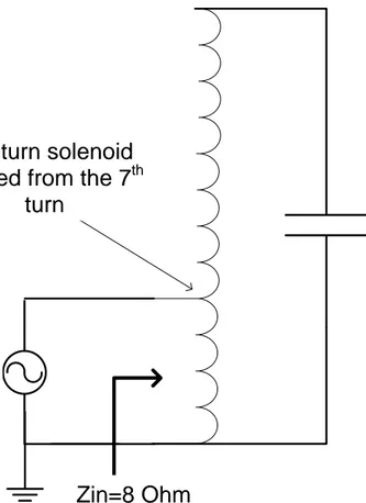
The circuit diagram of the matching circuit can be seen in Figure 8 below.
Figure 7. General experimental setup used in the experiments. DC Solenoid AC Solenoid DC Solenoid Matching Circuit Amplifier Signal Generator DC Power Supply Data Acqusition Device Temperature Probe Ferrofluid containing cup
Here, 1.46nF capacitor is connected in parallel to the solenoid (2.7mH) terminals to cancel out the reactive part of the inductor impedance, at 80 kHz. To obtain the necessary amount of current flow in the coil, the voltage between the solenoid (inductor) terminals should be very high. For this purpose, solenoid is excited from the 7th turn and it is used as a self transformer to amplify the voltage at the input. Determination of the 7th turn is done by using a network analyzer according to match the input of the transformer to the 8 Ohm output of the amplifier.
During the excitation of the system, on account of skin and proximity effects [18, 19] the AC coil heats up and because of the very high static current of the DC coils considerable heating occurs in the coppers of these solenoids as well. To overcome
Zin=8 Ohm
300 turn solenoid
Excited from the 7
thturn
1.46nF
Amplifier
the excessive heating of the system, water cooling is done by circulating water from the interior side of the solenoids.
As we mentioned before, the focused ablation system has the ability of shifting the heating focus (i.e. FFR). The field free region is produced around a point (field free point, FFP), on the solenoid axis, at which the magnetic field generated by the left solenoid cancels the field of the right solenoid. When same amounts of currents to both solenoids are applied the FFP will be formed at the center. On the other hand, if we increase the current of the left solenoid, the field free point shifts to the right by the increasing of the magnetic field generated by the left solenoid.
3.3 Experiments
To validate the focused heating ability of the ablation system several in vitro and in vivo experiments were made. During the experiments three different DC magnetic field conditions were tested by applying static currents of 0.5A, 1A and 1.8 A to both DC solenoids. As we explained previously by increasing the currents of the DC solenoids our aim is to decrease the volume of the field free region (FFR) to obtain more intense focus.
In vitro experiments
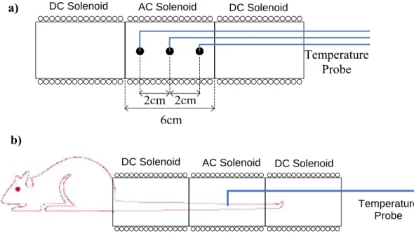
In vitro experiment setup can be seen in Figure 9a. Inside the AC solenoid three ferrofluid-containing spherical plastic cups of diameter 0.4cm were placed which were filled with a ferrofluid with an average core size of 10nm where weight fraction of magnetite is slightly bigger than %20 (Liquids Research Ltd.,
www.liquidsresearch.co.uk) and glue mixture. Glue was used to prevent the pouring of the ferrofluids. First cup was placed at the center (inside the FFR) and others are
put 2cm left and right of this cup. Temperature measurements were made by using fiber optic temperature probes. An AC magnetic field with strength of 4.5kA/m (with solenoid current of 1.8 Apeak) at 80 kHz was applied and corresponding temperature increases of the cups were recorded at different DC magnetic field conditions. Obtained temperature versus time graphs can be seen in Figure 10. From these figures, by using the rate of temperature rise method (c*∆T/ ∆t) SAR
(Specific Absorption Rate) calculations were made and tabulated in Table 1. Here, c is the specific heat of the heated magnetic material and ∆T is the differential
increase of the temperature for a differential time of ∆t seconds.
Another in vitro experiment was done again by using the setup of Figure 9a, but in this case different current magnitudes of 0.2A and 1.8A were applied to the left and right solenoids. Aim of applying different magnitudes of currents is to show how the position of the field free region shifts. Again, corresponding temperature rise curves of the cups are obtained and analyzed in the results section.
Temperature Probe DC Solenoid AC Solenoid DC Solenoid
6cm
DC Solenoid AC Solenoid DC Solenoid
Temperature Probe 2cm 2cm a) b)
In vivo experiments
In vivo experiments were done on the tails of 200g adult rats (obtained from Ankara Hospital Animal Experiment Laboratory). Ferrofluids with an average core size of 10nm were injected percutaneously to the tails of the anesthetized rats and
homogenous distribution of the fluid was observed from equally distributed color changing of the tail. A tourniquet was made at the proximal end of the tail to prevent the diffusion of the ferrofluid in to the systemic blood circulation. After injection of the ferrofluid, rat tail was placed along the axis of the solenoids as in Figure 9b. Fiberoptic temperature probe was placed in the tail portion
corresponding to the center of the FFR region to monitor the maximum temperature change in the tissue. An AC magnetic field with strength of 7.6kA/m at 80 kHz was applied and resultant temperature increase was recorded at different DC magnetic field conditions. 24 hours after the experiments rat tails were cut and fixed in %4 formaldehyde solution and send to the histological examination.
In this in vivo experiment, the rat tail was used as a model because the tail
comprises the whole region that AC field exist (which will help us to observe that some parts of the tail don’t be ablated although they are exposed to alternating magnetic field); in addition since the tail is composed of different types of tissues like bone, skin, muscle etc. it is very suitable to detect ablation from different kinds of tissues...
3.4 Results
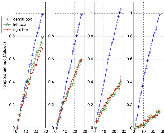
Temperature versus time graphs of the in vitro experiments are shown in Figure 10.
Here as we can see the temperature rise of the lateral cups placed 2 cm away from the center) decreases as the amplitude of the DC solenoid current increases. Besides that, temperature increase of the central cup isn’t affected from the altering of the DC field strength (since the cup stays in the field free region). This shows us that by increasing the magnitude of the DC field gradient we can decrease the temperature
Figure 10. Temperature rise versus time graphs of the in vitro experiments. Graphs are corresponding to DC solenoid currents of 0A,
0.5A, 1A and 1.8A respectively.
0 10 20 30 0 0.2 0.4 0.6 0.8 1 DC current=1.8A 0 10 20 30 0 0.2 0.4 0.6 0.8 1 DC current=1A 0 10 20 30 0 0.2 0.4 0.6 0.8 1 DC current=0.5A 0 10 20 30 0 0.2 0.4 0.6 0.8 1 DC current=0A time(sec) te m p er at u re r is e (C el c ius ) cenral box left box right box
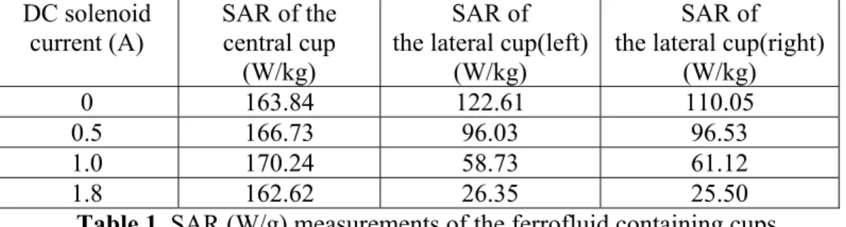
rise about the very vicinity of the center while the temperature at the center doesn’t change. Specific absorption rate of the cups are calculated as explained in the experiments section and the results are presented in Table 1.
DC solenoid current (A) SAR of the central cup (W/kg) SAR of the lateral cup(left)
(W/kg)
SAR of the lateral cup(right)
(W/kg)
0 163.84 122.61 110.05
0.5 166.73 96.03 96.53
1.0 170.24 58.73 61.12
1.8 162.62 26.35 25.50
Table 1. SAR (W/g) measurements of the ferrofluid containing cups
As we can see from Table 1, while current of the DC solenoids increases from zero to 1.8A, SAR of the lateral cups decrease from 110W/g to 25W/g. and the SAR of the central cup remain around 160W/g. These results show us that the system successfully focuses the heating around the center and the intensity of the focus can be easily improved by increasing the currents of the DC solenoids.
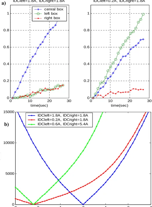
As explained in the experiments part, another in vitro experiment was done to observe the shifting of the FFR region by applying different magnitudes of currents (IDC) to the DC solenoids. Here 0.2A was given to the solenoid on the left hand side and 1.8A was given to the solenoid on the right hand side. Corresponding temperature curve is shown in Figure 11a on the right. Looking at the figure one can observe that maximum heating was seen in the left cup which demonstrates that the field free region shifted to the left. To visualize the existing static field strengths between the solenoids, analytical calculation of the fields on the solenoid axis is done and shown in Figure 11b. By looking at the field curves, we see that when we apply currents of IDCleft=0.2A and IDCright=1.8A the center of the FFR shifts to the left by approximately 2cm. But one thing should be pointed out that the size of the field free region increases (intensity of the focus decreases) compared to the
case where the solenoids are excited with 1.8A. This fact can be also detected from the temperature curves of Figure 11a. By looking at the temperature curves, one can see that, when maximum heating was observed in the left cup, a considerable temperature rise is also observed in the central cup which is not the case when both solenoids were excited with1.8A (where the temperature rise of left and right cups were very small). We observed that, while shifting the position of the centered FFR by 2cm, to preserve the size of the field free region, one should give currents of 1.8/3=0.6A to the left solenoid and 1.8*3=5.4A to the right solenoid. The
corresponding static field strength plot is also shown in Figure 11b. As can be seen, the shape of the field curve (so the static field gradient) is very similar to the case when 1.8A is given to both solenoids.
Figure 11. a) Temperature rise curves of the three cups for IDCleft=1.8A, IDCright=1.8A and IDCleft=0.2A, IDCright=1.8A b)Theoretical field strength plots for IDCleft=1.8A, IDCright=1.8A; IDCleft=0.2A, IDCright=1.8A and IDCleft=1.8/3=0.6A,
IDCright=1.8*3=5.4A. Here shape of the green curve is very similar to
blue curve showing that while shifting the centered FFR, the size and shape
-3 -2 -1 0 1 2 3
0 5000 10000 15000
Space between the DC solenoids(cm)
H0 (A /m ) IDCleft=1.8A, IDCright=1.8A IDCleft=0.2A, IDCright=1.8A IDCleft=0.6A, IDCright=5.4A 0 10 20 30 0 0.2 0.4 0.6 0.8 1 IDCleft=1.8A, IDCright=1.8A time(sec) te m per at ur e( C e lc iu s ) cenral box left box right box 0 10 20 30 0 0.2 0.4 0.6 0.8 1 IDCleft=0.2A, IDCright=1.8A time(sec) a) b)
So, in summary, if both solenoids are excited with a static current of IDC, the field free region will be at the center of the solenoids. If we decrease one of the solenoid currents, the position of the FFR will be shifted but in this condition the size of the region becomes larger than the centered FFR. If one wants to shift the FFR while preserving its shape and size, he or she should excite the solenoids with IDC*k and IDC/k respectively, where k is a constant rational number.
As explained in the experiments section, in vivo hyperthermia experiments were done for three different DC field strengths. AC field exposure lasts nearly 25 minutes and temperatures above 46ºC were obtained for all three experiments. A sample curve from one of the experiments can be seen in Figure 12 below.
0 200 400 600 800 1000 1200 1400 1600 28 30 32 34 36 38 40 42 44 46 48 time(sec) te m p er a tur e (C e lc iu s )
Figure 12. Typical temperature versus time graph of the in vivo experiments.
24 hours after the experiments, significant slimming and molting was observed on three of the rat tails. As shown in the in the photographs of Figure 13, size of the molting region decreases as the applied static magnetic field strength increases, again which verifies macroscopically that an ablation with higher intensity is achieved as the currents of the DC solenoids increased.
Figure 13. Rat Tail Photographs 24 hours after the hyperthermia application. Focused Ablation regions are marked and measured by a vernier caliper. a) For DC cureents of 0.5A, FFR≈2.2cm.
b) For DC cureents of 0.5A, FFR≈1.5cm. c) For DC cureents of 0.5A, FFR≈0.7 cm.
a)
b)
Here as shown in the a,b,c parts of Figure 13, the focused regions are measured with a vernier caliper and the sizes of about 2.2cm, 1.5cm and 0.7 cm were measured corresponding to DC solenoid currents of 0.5A, 1A and 1.8A respectively.
3.5 Discussion
It is shown that focused heating of magnetic domains can be achieved successfully by depositing DC field gradients on AC fields such that a region free of DC
magnetic field (FFR) is produced in the presence of AC magnetic field.
As demonstrated in the results of the experiments, intensity of the heating focus can be easily improved by increasing the DC magnetic field gradient i.e. by applying higher magnitudes of currents to the DC solenoids. In addition, the position of the focus (FFR) can be simply changed by applying different magnitudes of currents to the DC solenoids. While changing the position of the focus, to preserve the shape and size of the FFR, the currents of the DC solenoids should be selected carefully as explained in detail in the results section.
The system implemented in this paper can shift the focus in one dimension (along the axis of the solenoids). 3D movement of the focus can be achieved by using gradient coil sytems of the MRI scanners. In Figure 14, a sample gradient coil system is shown [16], where DC field gradients in all 3 dimension can be obtained.
The importance of shifting the location of the FFR is without changing the position of the patient, tumors with any possible geometry can be ablated by moving the FFR over the tumor. By using the presented ablation system (composed of 2 DC solenoids), again tumors with any shape can be ablated, but in this case while the FFR region stays at the center, the patient should be moved by very accurate robotic devices according to the shape of the tumor.
As explained, focused ablation system implemented in this study uses air-cored DC solenoids to generate the necessary static DC field gradients. Another possible implementation can be done by using iron cored solenoids. Since iron cored solenoids produce higher magnetic flux densities more intense focus can be obtained. But in this configuration placement of the patient in to the AC solenoid can be challenging. A further design can be done by using very strong permanent magnets instead of DC solenoids. With the permanent magnets, the movement of the focus can be achieved by changing the positions of the magnets.
Y gradient coils X gradient coils Z gradient coils
Figure 14. MRI gradient coil system. Gredients in all 3 dimensions can be generated. Figure is taken and modified from the reference 16.
Focused ablation system demonstrated in this study is not restricted to operate with superparamagnetic materials. Other magnetic material types, like multi domain ferromagnetic materials can also be used for the focused heating applications. The heating mechanism of multidomain ferromagnetic materials differs from the single domain superparamagnetics such that the power absorption occurs by hysteresis losses. If we use multidomain particles inside the system, as in the
superparamagnetic particle case only the multidomain ferromagnetic particles residing in the field free region will be heated but in this case power dissipation will occur by traversing the hytheresis loop. The materials outside the FFR stay in the saturation state and can’t traverse the hysteresis curve and no heat production will occur. But since the heat production via hysteresis loss requires large field
amplitudes, it can cause unwanted eddy current heating of the healthy tissues. As a result, using superparamagnetic particles, ferrofluids, clearly seems to be a much better method in the application of the focused hyperthermia.
Optimization of the ferrofluids is very important in focused ablation of the tumors. Optimal hyperthermia parameters (ferrofluid particle size, magnetic field strength, frequency) considering the human safety limits was previously studied [17]. By the production of ferrofluids with optimal properties very low amount of fluids can be sufficient to ablate the tumor in consideration. In fact, fluids can be given in to the systemic circulation and by moving the focus over the tumor geometry; tumor can be ablated successfully. For example, by staying below the safety limits, for a ferrofluid[17] with a mono disperse magnetite particle radius of 7.25nm and a volume fraction of 5 percent, 0.015 ml of fluid can be adequate for the treatment of 1 ml tumor tissue(Calculations were done using the equations of reference 4). Moreover, by the help of high power loss fluids (fluids with optimum
In hyperthermia the AC field magnitude which can be given to the patient has a limit [6] as seen in the expression below.
For a given frequency value, after a certain strength of magnetic field, healthy tissues start to be heated as a result of induced eddy current flows. More specifically, for a hyperthermia treatment with a frequency of 100kHz, the maximum amplitude of magnetic field that can be applied is around 5kA/m. Relatively small alternating magnetic fields(like 10-20kA/m) can be generated by solenoid type applicators[1], with a water cooling setup to overcome the heating resulting from skin and proximity effects [18,19]. There is no strict limit exists for the magnitude of DC field that a patient can be exposed. So, without any restriction, very high gradients of static magnetic fields can be used to produce very intense heating focus. In fact, pointwise heating of the magnetic particles can be achieved. But generation of high field gradients requires very large magnitudes of DC current flow, where water cooling can not be a satisfactory for the cooling of the coils. For this purpose, usage of super conductive wires in the construction of DC solenoids can be a reasonable solution.
For the correct localization of the FFR region on the tumor tissue the focused ablation system should be guided with an imaging modality. Among the traditional imaging techniques it is obvious that MRI will not be compatible with this system because of the highly magnetic components (like solenoids etc.) of the system. CT and ultrasound can be used for the imaging purpose. Perhaps, the CT guidance should be done before the application of the heat treatment, because in the presence of high magnetic fields Xrays of CT can be deflected. For the ultrasound case, the core of the heating system should be constructed large enough for the proper
8 0 4.85 10 (A/m) f H ≤ ×
Conclusion
A novel focused ablation system, capable of heating deeply seated tumors without damaging any surrounding tissue is presented and verified through experiments. By the usage of this newly developed heat treatment system, magnetic fluid
hyperthermia can be a much more effective heat treatment method, in the absence of the risk of heating healthy collateral tissues. Future works can be the combination of the heating system with a suitable imaging method and the construction of the DC solenoids by using super conductive wires to overcome the excessive copper heating. In addition, systems capable of 3D shifting of the heating focus can also be implemented. Furthermore, primary concern should be given to the optimization of the ferrofluids which will lead to the ablation of tumors with very small amounts of fluid injections, in very small treatment durations.
Bibliography
[1] Mornet S, Vasseur S, Grasset F, Duguet E, "Magnetic nanoparticle design for medical diagnosis and therapy", J. Mater. Chem., 2004, 14, 2161-2175
[2] Jordan A, Wust P, Fahling H, John W, Hinz A, Felix R, “Inductive heating of ferrimagnetic particles and magnetic fluids: physical evaluation of their potential for hyperthermia”, Int J Hyperthermia, 1993; 9: 51-68
[3] Hergt R, Andra W, d’Ambly C G, Hilger I, Kaiser W A, Richter U, Schmidt H-G, “Physical Limits of Hyperthermia Using Magnetite Fine Particles”, 1998 IEEE Trans. Magn. 34: 3745–3754
[4] R.E. Rosensweig, “Heating magnetic fluid with alternating magnetic field 2002”, J. Magn. Magn. Mater. 252 370–4
[5] Schaefer DJ, Bourland JD, Nyenhuis JA, “Review of patient safety in time-varying gradient fields”, J Magn Reson Imaging 2000, 12:20-29.
[6] Atkinson W, Brezovich IA, Chakraborty DP, “Usable frequencies in hyperthermia with thermal seeds”, IEEE Trans Biomed Eng 1984; 31:70-75 [7] Moroz P, Jones SK, Gray BN, "Magnetically mediated hyperthermia: current status and future directions", Int J Hyperthermia, 2002, 18(4):267 – 284
[8] Moroz PJ, Stephen K.; Gray, Bruce N. (2001),"Status of hyperthermia in the treatment of advanced liver cancer", Journal of Surgical Oncology 77, 259-269 [9] Masashige Shinkai, “Functional Magnetic Particles for Medical Application”, Journal of Bioscience and Bioengineering, Vol. 94, No.6, 606-613. 2002
[10] Johannsen M, Jordan A, Scholz R, Koch M, Lein M, Deger S, Roigas J, Jung K, Loening S, "Evaluation of magnetic fluid hyperthermia in a standard rat model of prostate cancer", Journal of Endourology, Volume 18, Number 5, June 2004 [11] Fumiko Matsuoka, Masashige Shinkai, Hiroyuki Honda, Tadahiko Kubo, Takashi Sugita, Takeshi Kobayashi, "Hyperthermia using magnetite cationic
liposomes for hamster osteosarcoma", Biomagnetic Research and Technology 2004, 2:3
[12] Bernhard Gleich, Jurgen Weizenecker, "Tomographic imaging using the nonlinear response of magnetic particles", Nature Biotechnology, Vol 435, 30 June 2005, doi10.1038
[13] Brown W F Jr 1963, "Thermal fluctuations of a single-domain particle", Phys. Rev. 130 1677–86
[14] Neel, L., "Theorie du trainage magnetique des ferromagnetiques en grains fins avec applications aux terres cuites", Ann. Geophys. 5, 99-136, 1949
[15] M. Babincova, D. Leszczynska, P. Sourivong, P. Cicmanec, P. Babinec, J. Magn. Magn. Mater. 225 (2001) 109-112
[16] http://homepage2.nifty.com/kirislab/chap5_mri/mri_images/imagingSystem/ gradientCoilSet
[17] T. O. Tasci, A. Arat, E. Atalar, “Optimization of MRI Contrast Agents for Magnetic Fluid Hyperthermia Considering the Human Safety Limits”, ISMRM, 2006,
[18] The Wireless Engineer, vol. 11, pp. 12–16, Jan. 1934, summary of work by S. Butterworth.
APPENDIX A
Introduction
Multimodality treatment of arteriovenous malformations (AVMs) involves endovascular treatment, surgery and radiotherapy [1, 2]. Currently the standard endovascular treatment involves obliteration of the malformation or the fistula with cyanoacrylic glue, OnyxTM or in some cases by particles such as PVA.
Interventional treatment of tumors also involves the same endovascular tools. The chance for an endovascular cure with cyanoacrylates only, is not high [3, 4]. This is mainly because of the technical difficulties related to the use of acrylic glue [5-8]. This entails expertise, attention and adherence to a strict technique which was developed over the years to prevent either inadvertent embolization or gluing of the catheter to brain vessels [6, 8]. Among these two complications, gluing of the catheter tip is a well-recognized complication [3, 5, 6, 8-18] that may be distressing [19]. In several series, this complication has been reported to be up to 10 %,
sometimes with serious outcomes [15, 20] and the scarcity of literature data may as well be secondary to under-reporting of this complication [9] with an unknown actual risk of permanent catheter fixation [5].
When gluing of catheter tip occurs, there are two methods for salvage. The first one is to leave the catheter in place, which is extending from the embolized lesion to the groin (access site). Although there are case reports documenting the incorporation of the retained catheters into the cerebral vasculature [21], it is also stated that epithelization does not occur quickly [9] increasing the risk of thromboembolic events. The patients with the retained catheters need to be followed under
anticoagulation or antiplatelet therapy [11] which is not preferred in patients with cerebral vascular malformations [22]. The number of embolization that can be performed via the same vascular pedicle is also limited with this approach, as with each subsequent embolization, there will be the risk of retaining more than one
catheter in intracranial arteries. The outcome of this approach is currently not well-known.
The second method is to severe the catheter at its distal portion by pulling with a sudden thrust and leaving the distal fragment of the catheter in the cerebral vasculature [6, 9, 11,13]. Despite the allegations of several authors that many
patients tolerate this maneuver, major morbidity and mortality has been documented as a result of the performance of this maneuver either secondary to vascular
avulsion/intracranial bleeding or to inadvertent embolization of polymerized glue by an adherent droplet being shorn from the tip of the microcatheter [3, 11, 14, 15, 16, 19, 23] and as such, catheter fixation remains a highly undesirable event among endoneurovascular operators. Surgical removal of these catheters may sometimes be needed [15].
The most important factor in preventing catheter adhesion is limitation or
prevention of reflux along the microcatheter [5, 6, and 18]. This not only requires considerable endovascular skills and expertise [5, 7], but also limits the success of the embolization procedure. The penetration of the embolic agent into the target site is enhanced by the formation of an "intravascular plug" at the catheter tip [8]. Generally, however, the formation of this plug necessitates a small reflux of the acrylic glue along the catheter tip.
Recently a precipitating embolic agent, Onyx, has been approved for the
endovascular treatment of AVMs [7, 12, 24]. Since this agent is non-adhesive, it permits prolonged injections for embolization [25]. As the experience with this material grows, it became apparent that using this agent with its full potential entails an intentional reflux of this material at the catheter tip to be bale to form an
"intravascular plug" [20]. This permits a higher rate of penetration to AVMs with a higher obliteration rate, at the expense of entrapment (instead of adhesion) of the
embolized in a randomized controlled trial [20]. As a matter of fact, a shift from the manufacturing of flow guided catheters to that of over-the-wire catheters was noted on the side of the company producing this embolic agent as the latter may be recovered better in case entrapment occurs.
As reflux of the embolic agent over the microcatheter tip is a major causative factor in the increased morbidity/mortality of embolization procedures and also a technical limitation preventing a better cure rate, we tried to eliminate this effect by
developing a method for the detachment of the microcatheters within the body, with no regard to the amount of reflux, at the proximal edge of the reflux, in order to be able to make embolization procedures safer and more effective.
In this work we had worked in collaboration with Anil Arat(M.D.) where he introduced the problem of catheter entrapment occurring in the endovascular treatments. He worked effectively in the conduction of experiments and design of some of the detachment techniques.
Methods
According to the procedure that we will explain, detachment of microcatheters within the blood vessel is done by heating the catheter tip via electrical energy. Electrical energy can be easily converted to heat by using electrical resistance wires. Examples of such wires used in the endovascular treatment currently are those utilized in the thermal detachment of Micrus® (Micrus Corporation,
Sunnyvale, CA) and Microvention coils ® (MicroVention, Aliso Viejo, CA). In the detachment process, we used the proximal segment (the segment proximal to the platinum coil, “the pusher”) of the Micrus-10 coil system which has an electrical resistance coil at its distal portion.
Generally speaking, the Micrus-10 wire is advanced through the catheter until the wire tip reaches the point where we want to detach the catheter. Afterwards
electrical energy is applied to the wire and the generated heat causes the catheter to melt and detach from the point it melts.
An experimental setup for the testing of the detachment procedure is constructed, which can be seen in Figure A1. As shown in the figure, a plastic tube (simulating arteries), a microcatheter with non-braided tip and an embolic agent (Onyx® 18 or 50 % acrylic glue, Histoacryl ® [n-butyl cyanoacrylate in Lipiodol ®]) was used and placed in to a water bath. The tip of the microcatheter was positioned within the tube and embolic agent was injected through the catheter to fill the tube. The lumen of the microcatheter was then flushed with DMSO or D5W for Onyx and glue respectively.
The pusher of a Micrus-10 coil (with the coil detached) was then advanced in to the microcatheter so that its tip was located within or just adjacent to the embolic cast. A fiber optic temperature probe (FISO Technologies, Ste. Foy, Quebec, and
Canada) was inserted near the tip of the coil pusher, which was also connected to the data acquisition device to directly monitor the temperature on the computer screen. The Micrus-10 wire was connected to a DC switching power supply and voltages from 5V to 15Volts were applied corresponding to different types of catheters. During the procedure catheter detachments were visualized by fluoroscopic imaging.
Results
In the experiments, for the embolizations with ONYX, we used Ultraflow™, Baltacci™ 18 and Fastracker® 325 catheters and for the embolizations with acrylic glue, we used Baltacci™, Spinnaker 18 and Ultraflow™ catheters. For the
experiments, where the coil pusher was within the embolic cast, all the catheters could be detached successfully. On the other hand, no detachment was observed when the tip of the coil pusher was adjacent (outside) the embolic cast. This shows us that the correct placement of the coil pusher tip is crucial (carrying the electrical resistance coil) for a successful catheter detachment. The results of the experiments are summarized in Table A1, can be seen below.
Table A1. Summary of the experimental results
For those experiments, where detachments occurred, bubble formation was observed with fluoroscopic imaging.
During the experiments catheter temperature at the detachment region was monitored continuously.
Corresponding to the detachment of the Ultraflow catheter with input voltage of 10Volts, the following temperature-time graph was observed in Figure A2. Here power is given for 25 seconds and detachment is successful. From the figure, one can see that the maximum change in the temperature is around 14 degrees Celsius. In summary, independent of their brands, all of the catheters with non-braded tips could be detachable by the method that we have explained above. Furthermore this method can be applicable to puncture or ablate intravascular tools like endovascular balloons or stent grafts as well as tissues like vessel wall or membranous tissues.
Embolization
Material Type Catheter Type
Position of the wire tip wrt. the
catheter
Result
ONYX Ultraflow Distal Detached
ONYX Ultraflow Proximal Non- Detached
ONYX Baltacci Distal Detached
ONYX Fast Tracker 325 Distal Detached
ONYX Fast Tracker 325 Proximal Non- Detached
GLUE Baltacci Distal Non- Detached
GLUE Spinhacker Distal Detached
80 100 120 140 160 180 200 220 240 22 24 26 28 30 32 34 36 38 40
Temperature versus time graph at a given voltage of 10 Volts
time(s) te m p er a tu re( deg re e c e lc iu s )
Figure A2. Wire tip temperature versus time graph, at a given
Discussion
In addition to the explained method, other modalities can be used for the aim of catheter detachment, including laser, RF or mechanical energies and alike. As we previously described, one method of detachment involves placement of the high resistance coil inside the microcatheter (Figure A3a).
Figure A3. a) Detachment method by heating from inside b,c) Detachment methods by heating from outside
Another method for detachment of catheters is to introduce the microcather used for embolization through the open loop of snare which harbors an electrical circuit and at its tip, a high resistance coil. This snare is located within a second catheter as seen in Figure A3b. After the embolization, this assembly is advanced over the catheter through which embolization was performed, using it as a guide, until the desired detachment point is reached. Then the loop of the snare is tightened by advancing the second catheter over the snare. Once the snare is tightened,
detachment is performed by application of current through the snare-resistance coil assembly.
In another method, a coaxial system is formed with the embolizing catheter located innermost, with the second catheter placed outermost and the snare-resistance coil
assembly located in between these catheters as in Figure A3c. Again, the loop of the snare-resistance coil assembly is tightened by advancement of the outermost catheter over this assembly.
An alternative method by electrical heating is described in Figure A4. Here high resistance coil is encircled around a deflated balloon, which is advanced through the catheter until it reaches to the detachment side. At the detachment region, balloon is inflated and high resistance coil completely touches to the inner wall of the catheter. Afterwards, power is applied to the coil and catheter is detached by heat. For this procedure balloon should be made from a heat resistive material to prevent it from bursting as a result of the hot coil or alternatively, it may be deflated before application of the current. With this method, independent of the catheter radius, all of the non-braded catheters can be detached, since the heater coil dimension is adjusted to the catheter radius by balloon inflation.
Besides the previously explained designs including the design used in the Micrus coil, the resistance coil – current carrying wire combination may be built in different forms. For example the circuit may be formed by an assembly which is made of a hypotube connected
distally, to an interposed piece of resistance wire, which is also connected to an insulated cupper wire that is placed within the hypotube to complete the electrical circuit.
In addition to electrical heating, detachments can be done also mechanically. A possible approach can be seen in Figure A5. In this assembly catheter tip is
surrounded by a lasso-shaped rope which is connected to the edge of a pusher wire. The wire material can be constructed from materials such as nitinol for a better conduction of mechanical force from bottom to top. First of all, the wire (“rope”), together with the auxiliary catheter, is advanced over the first microcatheter using it
pushed against the embolic cast to buttress the feeding vessel and prevent it being severed while pulling force is applied to the microcatheter to detach it from the cast. This is similar to unplugging a plug from the socket on the wall, that is when one hand pushes against the socket to stabilize it, the other hand pulls the plug out of it.
Other means of a mechanical detachment can be achieved by cutting the catheter using micro-scale knives as shown in Figure A6. Like the previous case, catheter tip is surrounded by a rope, but in this situation, it has very small knives on it. When the rope is tightened by means of the auxiliary catheter, knives directly grip the catheter and these results in the cutting of the tip. In contrast to the previously explained ones this technique can also be applicable to the braided catheter types.
Furthermore, other energies like laser energy can also be used for the detachments. A possible configuration is shown in Figure A7. As can be seen from the cross-sectional view, laser beam is sent to the catheter tip throughout a fiber-optic cable. At the end of the fiber-optic cable, two different glass mediums with refraction indexes n1 and n2 are placed. Medium with refraction index n2 has a conical shape and has a tip angle of α, where α is selected so that the incoming light is reflected directly to the catheter wall. By this way, catheter wall is melted from inside and detachment is accomplished.
Apart from the techniques we have explained above, electrical detachments can also be done by applying RF or microwave or ultrasound energies. In addition,
detachments can be achieved chemically by injecting hot gases or other chemical substances into or around the tip of the catheters. Furthermore other mechanical detachments can be performed including cutting from the inside of the catheters.
Conclusion
A novel method, for the detachment of microcatheters by means of electrical energy is explained in detail.
Furthermore, various additional catheter detachment techniques are proposed. All except one of the proposed procedures enable the detachment of non-braided catheters independent of their brands. As a consequence, these techniques can directly be applied to the commercially available catheters without a need for a novel detachable catheter design.
Figure A7. Cross-sectional view of the catheter detachment procedure
References
[1] Soderman M, Andersson T, Karlsson B, Wallace MC, Edner G. Management of patients with brain arteriovenous malformations. Eur J Radiol. 2003 Jun; 46(3):195-205.
[2] Al-Shahi R, Warlow C. Arteriovenous malformations of the brain: ready to randomise?. J Neurol Neurosurg Psychiatry. 2005 Oct;76(10):1327-9.
[3] Ruckert RI, Bender A, Rogalla P. Popliteal artery occlusion as a late
complication of liquid acrylate embolization for cerebral vascular malformation. J Vasc Surg. 1999 Mar; 29(3):561-5.
[4] Yu SC, Chan MS, Lam JM, Tam PH, Poon WS. Complete obliteration of intracranial arteriovenous malformation with endovascular cyanoacrylate
embolization: initial success and rate of permanent cure. AJNR Am J Neuroradiol. 2004 Aug;25(7):1139-43.
[5] Mathis JM, Evans AJ, DeNardo AJ, Kennett K, Crandall JR, Jensen ME, Dion JE. Hydrophilic coatings diminish adhesion of glue to catheter: an in vitro simulation of NBCA embolization. AJNR Am J Neuroradiol. 1997 Jun-Jul; 18(6):1087-91.
[6] Aletich VA, Debrun GM. Intracranial arteriovenous malformations: The approach and technique of cyannoacrylate embolization. In: Connors JJ, Wojak JC editors. Interventional Neuroradiology: Strategies and Practical Techniques. 1st ed. Philadelphia: WB Saunders; 1999. p. 240-259.
[7] Molyneux AJ, Coley SC. Embolization of spinal cord arteriovenous malformations with an ethylene vinyl alcohol copolymer dissolved in dimethyl sulfoxide (Onyx liquid embolic system). Report of two cases. J Neurosurg. 2000 Oct; 93(2 Suppl):304-8.
[8] Jordan O, Doelker E, Rufenacht DA. Biomaterials used in injectable implants (liquid embolics) for percutaneous filling of vascular spaces. Cardiovasc Intervent Radiol. 2005 Sep-Oct; 28(5):561-9.
Surg Neurol. 1996 Dec; 46(6):562-7.
[10] Laurent A. Materials and biomaterials for interventional radiology. Biomed Pharmacother. 1998;52(2):76-88.
[11] Pollak JS, White RI Jr. The use of cyanoacrylate adhesives in peripheral embolization. J Vasc Interv Radiol. 2001 Aug; 12(8):907-13.
[12] Castaneda F, Goodwin SC, Swischuk JL, Wong GC, Bonilla SM, Wang MJ, Abdel-Sayed PS. Treatment of pelvic arteriovenous malformations with ethylene vinyl alcohol copolymer (Onyx). J Vasc Interv Radiol. 2002 May; 13(5):513-6. [13] Kerber CW, Wong W. Liquid acrylic adhesive agents in interventional neuroradiology. Neurosurg Clin N Am. 2000 Jan; 11(1):85-99.
[14] Richling B, Killer M. Endovascular management of patients with cerebral arteriovenous malformations. Neurosurg Clin N Am. 2000 Jan; 11(1):123-45. [15] Thornton J, Aletich VA, Misra M, Debrun GM, Dovey Z, Ausman JI.
Management of retained catheter tip following glue embolization for Brain AVMs. Radiology. 1999; 213 Suppl 1:S393.
[16] Sellar RJ. Cerebral Arteriovenous Malformations. In: Butler P. ed.
Endovascular Neurosurgery: A Multidisciplinary Approach: 1st ed. New York: Springer Verlag; 2000. P.73-96.
[17] Teksam M, McKinney A, Truwit CL. A retained neurointerventional microcatheter fragment in the anterior communicating artery aneurysm in multi-slice computed tomography angiography. Acta Radiol. 2004 May;45(3):340-3. [18] Howington JU, Kerber CW, Hopkins LN. Liquid embolic agents in the treatment of intracranial arteriovenous malformations.mNeurosurg Clin N Am. 2005 Apr; 16(2):355-63.
[19] Barr JD, Hoffman EJ, Davis BR, Edgar KA, Jacobs CR. Microcatheter adhesion of cyanoacrylates: comparison of normal butyl cyanoacrylate to 2-hexyl cyanoacrylate. J Vasc Interv Radiol. 1999 Feb; 10(2 Pt 1):165-8.
[20] Premarket Approval (PMA) for Onyx@ Liquid Embolic System (LES). Rockville MD: Food and Drug Administration,Dockets Management Branch;Jul 2005. Docket #.: 2005M-0328. PMA Number: PO30004.
[21] Zoarski GH, Lilly MP, Sperling JS, Mathis JM. Surgically confirmed incorporation of a chronically retained neurointerventional microcatheter in the carotid artery. AJNR Am J Neuroradiol. 1999 Jan;20(1):177-8.
[22] Link MJ, Schermerhorn TC, Fulgham JR, Nichols DA.
Progressive neurological decline after partial spontaneous thrombosis of a Spetzler-Martin Grade 5 arteriovenous malformation in a patient with Leiden factor V mutation: management and outcome. J Neurosurg. 2004 May; 100(5):940-5. [23] Morris P. Interventional and Endovascular Therapy of the Nervous System: A Practical Guide.st ed. New York:Springer Verlag;2002. P.296-311.
[24] Warakaulle DR, Aviv RI, Niemann D, Molyneux AJ, Byrne JV, Teddy P. Embolisation of spinal dural arteriovenous fistulae with Onyx. Neuroradiology. 2003 Feb; 45(2):110-2.
[25] Jahan R, Murayama Y, Gobin YP, Duckwiler GR, Vinters HV, Vinuela F. Embolization of arteriovenous malformations with Onyx: clinicopathological experience in 23 patients. Neurosurgery. 2001 May; 48(5):984-95.
APPENDIX B
Electrical circuit modeling of the X-Ray
Photoelectron Spectrometer and the Sample under
consideration
Introduction
X-ray photo electron spectroscopy (XPS) is a very powerful tool for determining chemical and structural properties of the surface structures in the nanometer scale. XPS is one of the most preferred spectroscopy techniques because all elements (except hydrogen) and their oxidation state(s) can easily be identified. However, analysis of poorly conducting materials has always been problematic due to the positive charging taking place during the XPS examination. Because of this charging phenomenon, significant binding energy shifts occur and incorrect spectrums are obtained. In consequence, understanding the charging mechanisms occurring in the XPS analysis is very important and it is necessary to take the spectrum corresponding to the zero surface potential condition to take correct spectrum.
Previously, charging of insulating samples during XPS and corresponding outcomes on the surface voltage were studied extensively by Cazaux [1, 2]. In his work, several parameters effecting charge compensation were stated and the role of those parameters on determining the surface potential was examined in a qualitative manner.
In our work, to achieve a better understanding of the charging mechanisms, the current paths passing through the sample under examination were investigated and modeled by electrical circuit elements. Electrical circuit modeling of the
spectrometer and the sample helps us to simulate various types of experimental conditions without making any XPS experiments. By using these simulations, very precise estimation of the surface voltage and corresponding XPS spectrum can be done for various types of input voltages. Consequently, one can easily find the zero surface potential condition and obtain the correct uncharged spectrum by using the model that we have proposed.