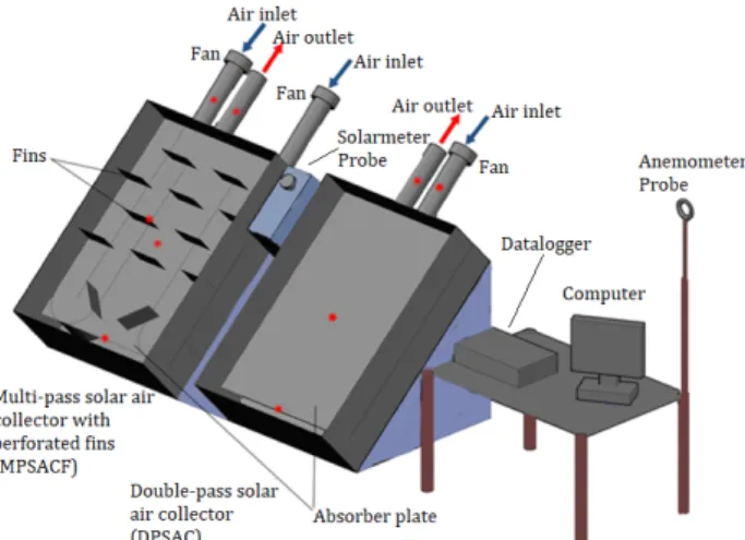
Energy-exergy analysis of a novel multi-pass solar air collector with perforated fins
Tam metin
Şekil

Benzer Belgeler
Figure 31: Efficiency of red PGSAH, violet PGSAH and UTSAH versus time of the day...53 Figure 32: Efficiency of white PGSAH, yellow PGSAH and UTSAH versus time of the
58 Figure 5.7: Temperature difference versus standard local time of the day at different mass flow rates: (a) 3 baffles (b) 5 baffles and (c) 7 baffles, for double- pass SAH, 5cm
The temperature differences of single and double pass solar collectors with either quarter or half perforated covers at low mass flow rate (ṁ=0.011 kg/s) are higher
Heat transfer coefficient and friction factor correlations for rectangular solar air heater duct having transverse wedge shaped rib roughness on the absorber
Buna göre, risk sermayesi şirketi mudarebe; proje sahibi girişimci şirket, mudarib; finansman sağlayan kamu kuruluşu veya özel sektör de rabbül-mal (sermayedar)
“Harç veya betonun inşaatta kullanılmaya hazır bir malzeme olarak şantiyeye getirilebilmesi kuşkusuz büyük bir avan- taj olurdu..” 1872 yılında dile getirilen ve
utilization of the Matlab program to estimate the thermal efficiency of D- F/GVCPSAC by solving the constructed heat balance equations and evaluate the useful
It was retrospectively evaluated whether there was a difference in the severity and course of stroke in acute ischemic stroke patients diagnosed with type-2 DM and taking
