618
Abstract
pp. 618-637
nOBS: an ns2 based simulation tool
for performance evaluation
of Tep traffic in OBS networks
Guray GUREL*, Onur ALPARSLAN**, Ezhan KARASAN*
Performance evaluation of TCP traffic in OBS networks has been under intensive study, since TCP constitutes the majority of Internet traffic. As a reliable and publicly available simulator, ns2 has been widely usedfor studying TCP/IP networks; however ns2 lacks many of the components for simulating optical burst switching networks. In this paper, an ns2 based OBS simulation tool (noBs
J,
which is built for studying burst assembly, scheduling and conten-tion resoluconten-tion algorithms in OBS networks is presented. The node and link objects in OBS are extended in nOBS for developing optical nodes and opticallinks. The ingress, core and egress node functionalities are combined into a common optical node architecture, which comprises agents responsible for burstification, routing and scheduling. The effects of burstification parameters, e.g., burstification timeout, burst size and number of burstification buffers per egress node, on TCP performance are investigated using nOBS for different TCP versions and different network topologies.Key words: Optical telecommunication, Optical switching, Burst switching, Simulator program, Numerical simulation, Internet, TCP/IP, Performance evaluation, Wavelength division multiplexing.
NOBS : UN OUTIL DE SIMULATION FONDÉ SUR NS2 POUR ÉVALUATION
DE PERFORMANCE D'UN TRAFIC TCP DANS LES RÉSEAUX
À
COMMUTATION OPTIQUE DE RAFALES
Résumé
L'évaluation de la performance d'un trafic TCP dans les réseaux à commutation optique de rafales est intensivement étudié puisque le trafic TCP constitue la plus grande partie du trafic de l'internet. Le simulateur ns2, fiable et accessible publiquement, a été largement uti-lisé pour étudier les réseaux TCP/IP, mais il ne dispose pas de nombreux composants néces-saires pour simuler les réseaux à commutation optique de rafales. L'article présente un outil de simulation fondé sur ns2, dénommé nOBS, qui a été construit pour étudier les algorithmes destinés à l'assemblage des rafales, à la planification et à la résolution des conflits dans les
*
Department of Electrical and Electronics Engineering, Bilkent University - 06800 Ankara, Turkey**
Graduate School of Information Science and Technology, Osaka University - 1-5 Yamadagaoka, Suita, Osaka 560-0871, Japana. aUREL - NOBS: AN Ns2 BASED SIMULATION TOOL FOR PERFORMANCE EVALUATION 619 réseaux à commutation de rafales. Les objets nœud et liaison sont étendus pour représenter des nœuds et liaisons optiques. Les fonctions de nœuds d'entrée, de cœur et de sortie sont combinées en une architecture commune de nœud optique, qui comprend les agents respon-sables pour l'assemblage des rafales, le routage et la planification. On étudie l'influence des paramètres tels que temporisation, taille des rafales et nombre de tempons d'assemblage par nœud d'entrée sur la performance pour différentes versions de TCP et différentes topologies de réseau.
Mots clés: Télécommunication optique, Commutation optique, Commutation rafales, Programme simulation, Simulation numérique, Internet, TCP/IP, Évaluation performance, Multiplexage longueur onde.
Contents
1. Introduction
II. Simulator architecture Ill. Simulation results
IV. Conclusions References (16 ref)
1. INTRODUCTION
Increasing demand for services with very large bandwidth requirements, e.g., grid net-works, facilitates the dep10yment of optical networking technologies [1]. Using Dense Wave-length Division Multiplexing (OWOM) technology, optical networks are able to meet the huge bandwidth requirements of future Internet Protocol (IP) backbones [2]. Currently, IP routers are interconnected with virtual circuits over synchronous optical networks (SONET) through multiprotocollabel switching (MPLS) [3]. However, optical circuit switching (oes) is not sui-table for carrying bursty IP traffic with time-varying bandwidth demand. In addition, delays during connection establishment and release increase the latency especially for services with small holding times. An alternative to oes is optical packet switching (oPs), which can adapt to changing traffic demands and requires no reservation, but the optical buffering and signal processing technologies have not matured enough for deployment of OPS in core networks in the near future.
Optical Burst Switching (OBS) is proposed as a short-term feasible solution that can com-bine the strengths and avoid the shortcomings of oes and OPS [4]. In OBS, the IP packets rea-ching the edge router are aggregated into bursts before being transmitted in the optical core network. Optical burst switching (OBS) is a sub-wavelength transfer mode that is halfway bet-ween optical circuit switching and optical packet switching. OBS separates the data and control planes in the optical and electrical domain, respectively, in order to eliminate the technological problems involved in the all-optical processing of the packet header in optical packet switching. A variable-Iength optical burst is composed of several IP packets in order to avoid small size optical packets, so that the stringent requirements for transmission and syn-chronization in the optical domain can be avoided.
nOBS enables performance analysis of OBS networks with wavelength converters and FOLS while carrying Tep traffic, and it implements various burst assembly, scheduling and routing algorithms. nOBS has been developed over ns2 [51.
620 G. GUREL - NOBS: AN Ns2 BASED SIMULATION TOOL FOR PERFORMANCE EVALUATION
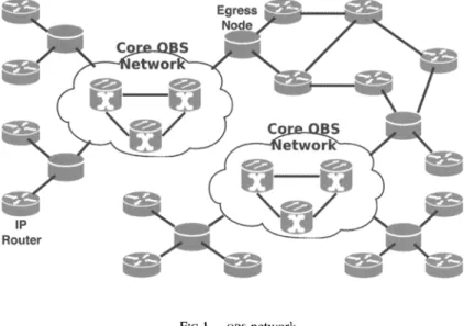
One of the first ns2 based optical burst switching network simulators is owns [6], which uses an older version of ns2 and implements a limited number of assembly, scheduling and routing algorithms for OBS networks. OIRC OBs-ns [7] is a re-designed and improved version of owns. However, OIRC OBs-ns does not allow simulating a network structure composed of OBS subnetworks (clouds) and electronic edge nodes as shown in Figure 1. Furthermore, OIRC OBs-ns supports only shortest path routing, whereas other routing algorithms cannot be used. On the other hand, nOBS can be used to simulate general OBS network topologies composed of optical clouds as shown in Figure 1. nOBS also aIlows use of any routing algorithm in an OBS network by implementing source routing.
A core OBS network model is shown in Figure 1 where OBS clouds interconnect edge routers. The edge nodes of an OBS network, i.e., ingress and egress nodes, fu1fill the burstifi-cation and deburstifiburstifi-cation functions. The edge node architecture in nOBS aIlows users to specify the parameters of the burst aggregation algorithm as weIl as how packets belonging to different TCP flows that are forwarded to the same egress node, are mapped into bursti-fiers. The edge nodes are also responsible for generating and transmitting the burst control packet, which corresponds to the burst header. The control packet has aIl the necessary information so that each intermediate optical switch in the core OBS network can schedule the data burst and also configure its switching matrix in order to switch the burst optically. nOBS uses the Just-Enough-Time (JET) reservation protocol [8], where the edge node trans-mits the optical burst after an offset time following the transmission of the control packet. In JET, the control packet tries to reserve resources for the burst just sufficient enough for trans-mission of the burst on each link it traverses. The core nodes in nOBS perform the scheduling function using wavelength converters and fiber delay lines (FOL), if necessary. In nOBS, the wavelength converters and FOLS are combined into pools that are shared among aIl ports. This sharing architecture is called Share-Node (SPN), which achieves the best loss per-formance among other sharing architectures [9]. The user can specify the number of FOLS and wavelength converters in the pools at each node. The scheduling algorithms that are currently implemented in nOBS are Latest Available Unused Channel with Void Filling (LAUC-VF) [10] and Minimum Starting Void (Min-sv) [11]. The routing of the bursts within the OBS network is performed in nOBS using the minimum-hop path between the ingress and egress nodes.
The paper is organized as follows. In the next section, the architecture of nOBS is descri-bed in detail. nOBS is used for studying the effects of burstification algorithms and parameters on TCP performance, and the results of this study are presented in Section III. Section IV concludes the paper.
II. SIMULATOR ARCHITECTURE
nOBS is developed by extending existing structures of ns2 (version 2.27). The node and link objects in ns2 are reconfigured with new components to become optical node and optical link. The address classifier at the node entrance has been replaced with a classifier that differentiates TCP segments from optical bursts. The implementation of the optical source routing agent helps realize typical OBS simulation scenarios.
G. GUREL - NOBS: AN Ns2 BASED SIMULATION TOOL FOR PERFORMANCE EVALUATION 621
FIG 1. - OBS network.
Réseau à commutation optique de rafales.
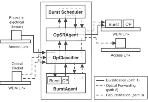
The architecture of an OBS node in nOBS is shown in Figure 2. Ingress, core and egress node functionalities are combined into the nOBS optical node and are indicated by paths 1, 2 and 3 respectively.
The process of burstification (path 1) starts with a packet in electrical domain arriving at the optical node through an access link. This packet is first processed by Optical Classifier (opclas-sifier). Upon seeing that the next hop for this packet is in the optical domain, opclassifier for-wards the packet to the Burst Agent (BurstAgent). BurstAgent puts the packet in an assembly buffer that corresponds to a burst and control packet pair. When a burst is ready for transmis-sion, its associated control packet is sent to opclassifier and then forwarded to Optical Source Routing Agent (opsRAgent). opsRAgent puts the optical domain routing information into the control packet and the corresponding burst. It then checks for a suitable interval through the Burst Scheduler block. This block includes opschedule, opconverterschedule and OpticalFDL-schedule, which keep records of the reservations on outgoing channels, wavelength converters and FDLS, respectively. If a suitable interval is found, opsRAgent sends the control packet and schedules the burst to be transmitted after an offset time. Otherwise, the burst is dropped.
opsRAgent is basically an ns2 source routing agent improved to handle optical packets. When the simulation scenario is described in the TCL code, all nodes (electrical or optical) are commanded to install an opsRAgent instance and routes for each node to all possible desti-nations are explicitly defined in the simulation scripts. Therefore, the users can select the routes of packets according to the paths generated by the specific routing algorithm used. In
aIl nodes, newly created packets are sent to opsRAgent, which writes the path that will be used by the packet in the packet header. In other words, if an application running on ingress router produces data to be sent into the OBS network, the burstification path starts with opS-RAgent, where the route information for the packet is written, followed by the opclassifier which will forward the packet to the BurstAgent.
Required functionalities of optical nodes are divided into four separate modules (Burst Scheduler, opsRAgent, opclassifier, BurstAgent) for reducing the model complexity and
622 G. GUREL - NOBS: AN Ns2 BASED SIMULATION TOOL FOR PERFORMANCE EVALUATION Packet in electrical domain Access link Optical Packet :
0 ... ··
---1 WOM link Burst
S~~~~le~
BurstAgent1
BurstIrcPl
[m__nmmnmmm) WOM linkï ___
..[J
,
Access link - Burstification (path 1) ••••••• Optical Forwarding (path 2) - - Deburstification (path 3)FIG 2. -Optical node architecture in nOBS. Architecture optique d'un nœud dans nOBS.
wing easier modification or addition of algorithms. AlI optical ingress, egress and core nodes require the same functionalities of Burst Scheduler, opsRAgent and opclassifier. The only difference between these node types is that core nodes may not need BurstAgent when there is no burstification and deburstification in the core. However, sorne users may also need to attach traffic agents and burstify/deburstify on the optical core nodes. Therefore, ingress, egress and core nodes share the same node architecture and there is no need to specify the type of the optical node when creating it in the simulation script.
In the case of optical forwarding (path 2), an optical packet is received by the opclassifier through an incoming WDM link. Since the next hop is in the optical domain, opclassifier for-wards the packet to the opsRAgent, which queries the Burst Scheduler block for a valid reser-vation. If the optical packet is a control packet and a reservation for the associated burst is possible, then the control packet is forwarded to the corresponding WDM link. If the optical packet is a burst and a reservation has been already made, the burst is forwarded to the WDM link. Otherwise, the optical packet is dropped.
When the next hop for an optical packet is not in the optical domain, opclassifier sends this optical packet to the BurstAgent for deburstification (path 3). If the optical packet is a control packet, it is dropped. If it is a burst, then the packets inside the burst are sent to the opclassifier, which forwards them to opsRAgent. opsRAgent sends the se packets through out-going electricallinks towards their destination nodes.
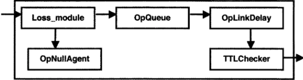
The architecture of an opticallink in nOBS is shown in Figure 3. This structure is based on the existing ns2 link configuration. Instead of the store-and-forwarding scheme of packet switched networks implemented in ns2, cut-through forwarding is applied. Original Queue of ns2 blocks the link for other packets during the transmission of a packet, until a scheduler
G. GUREL - NOBS: AN Ns2 BASED SIMULATION TOOL FOR PERFORMANCE EVALUATION 623
OpQueue
FIG 3. - WDM link architecture in nOBS.
Architecture d'une liaison à multiplexage en longueur d'onde dans nOBS.
event created by LinkDelay signaIs the end of the packet transmission. The oPQueue module in nOBS immediately forwards aIl incoming packets to opLinkDelay without any blocking, packet dropping or queueing since wavelength reservation, contention resolution and FDL
buffering operations are already performed by Burst Scheduler and opsRAgent in the node architecture. It was possible to remove 0PQueue and connect loss module and opDelayLÏnk directly, but oPQueue is kept for easier implementation of future OBS architectures, which may need a queue component on the links. When the Loss module associated with the link determines that an optical packet must be dropped, the packet is sent to opNullAgent compo-nent, which frees individual packets in si de the burst. The operations on the link are memory-less and independent of the wavelength. Therefore multiple packets arriving at the same time on different wavelengths can be served without affecting each other.
The main components of nOBS, the classifier, the burst agent, the source routing agent and the optical schedulers, are described below in more detail.
II.1. Op Classifier
A new classifier called opclassifier is implemented in nOBS for classifying and forwarding packets inside optical nodes. The id numbers of optical nodes in the same domain as this node are given to opclassifier in a TCL script by using the command opticnodes and stored in a table called opticnodes. Therefore, opclassifier knows the nodes that are in the same OBS domain. When a packet arrives to opclassifier, opclassifier checks the type and destination of the incoming packet and handles the packet as follows:
6/20
• If the incoming packet is not an optical burst and the packet' s destination address is not this node, opclassifier checks the source routing table of the packet. Looking up in the routing table of the packet, opclassifier checks whether the packet's next node is in opticnodes. If it is, the packet needs to enter the OBS domain, furthermore the node that owns this opclassifier should act as an ingress node and apply burstification. There-fore, opclassifier forwards this packet to the burstifier agent called BurstAgent. Other-wise, opclassifier realizes that this packet is coming from the BurstAgent after the deburstification process. In this case, the packet is leaving the OBS domain, so
624
G. GUREL - NOBS: AN Ns2 BASED SIMULATION TOOL FOR PERFORMANCE EVALUATIONsifier forwards this packet to the source routing agent that will forward the packet to the next hop over an electronic link.
• If the packet is an optical burst and the packet's destination address is this node, it means that a burst has reached its destination. opclassifier forwards the packet to the BurstAgent for the deburstification process.
• If the packet is an optical burst and the packet's destination address is not this node, it means that this is a burst in transit. Therefore, opclassifier forwards this packet to the source routing agent that will forward it to the next hop which is specified in the source routing table of the packet.
• If the packet is not an optical burst and the packet's destination address is this node, it means that the packet is coming from the BurstAgent after deburstification process and the receiver of this packet is in this node. opclassifier forwards this packet to the port classifier, which will forward the packet to its destination agent.
Il.2. BurstAgent
BurstAgent is responsible for the burstification of electronic packets and deburstification of optical bursts. A single BurstAgent is attached to opclassifier in each optical node. When a new packet arrives from opclassifier, BurstAgent checks whether this packet is an electronic packet or an optical burst. If the packet received from opclassifier is an optical burst, BurstA-gent disassembles the IP packets inside the payload of the burst and sends these IP packets
back to the opclassifier to be delivered to their destination agents.
If the packet is an electronic packet, BurstAgent compares the source routing table of the packet with the li st of nodes contained in the table opticnodes and finds the corresponding egress node from where this packet willleave the OBS domain. Next, BurstAgent inserts the incoming packet to one of the assembly queues responsible for burstifying packets destined for this destination egress node. The assembly algorithm implemented in the BurstAgent is a hybrid size/timer-based algorithm that keeps track of the size of the burst and the delay expe-rienced by the first packet in the burst. BurstAgent creates a burst when the delay of the first packet reaches a given timeout, or the number of IP packets in the burst reaches a threshold.
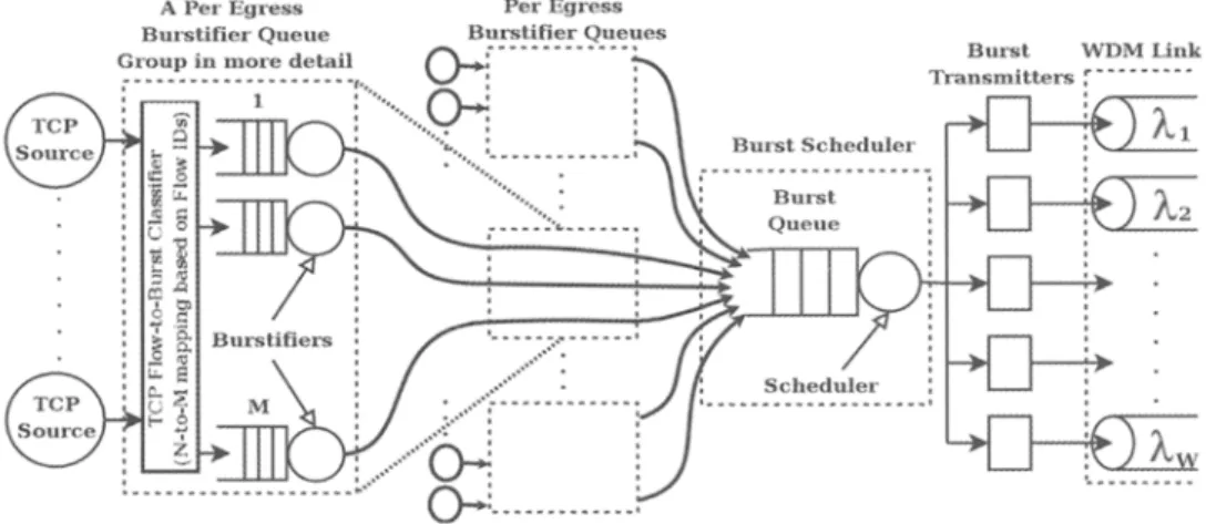
In our ingress node model, the number of assembly buffers per egress router, M, can be bet-ween 1 and the number of flows, N, as shown in Figure 4. An incoming packet is forwarded to a per egress burstifier queue group based on the routing information, and it is classified further into an assembly buffer based on the flow ID depending on N and M. If an incoming
optical packet is the first packet in the assembly queue, BurStAgent starts the burstification delay timer. When the burst is ready for transmission, BurstAgent creates a control packet carrying aIl the necessary information for this burst. Before sending the burst, BurstAgent copies the packets in the assembly queue to the burst's payload. Then, BurstAgent sends the control packet to opclassifier. Sending only the control packet to opclassifier is enough, because other agents in the node can reach the data packet by using a pointer contained in the control packet pointing to the optical burst to be transmitted.
nOBS also allows the user to select whether ACK packets will be burstified or not. Setting ackdontburst variable to 1 allows preventing burstification of ACK packets. In this case, ACK packets are sent to the OBS network as soon they are received and they are carried in the OBS network like ghost packets without any dropping or queuing.
G. GUREL - NOBS: AN Ns2 BASED SIMULATION TOOL FOR PERFORMANCE EVALUATION 625
A PerEgress
Burst Scheduler
v __
dT:::,
: ... ::::::':'.::::':'" ..
~
... o-J ... .:
FIG 4. - Ingress node mode!. Modèle d'un nœud d'entrée.
Burst WDMUnk
Âl
Â2
Â
II.3. OpSRAgent
A new source routing agent called opsRAgent is implemented in nOBS which is respon· sible for adding the source routing information to packets, forwarding the packets to links according to the routing infonnation, and controlling when and how to send optical packets using FDLS and wavelength converters. While creating a simulation scenario with nOBS, aIl the nodes are configured with source routing information within the TeL script. Electrical
nodes are configured only with ingress and egress routers of aIl OBS networks, while optical nodes are infonned of routes within the OBS subnetwork they belong to. Using a separate source routing table for optical nodes provides the abstraction, i.e., the cloud structure com-posed of OBS subnetworks, of the core network within the general topology as shown in Figure 1.
When opsRAgent receives a packet, opsRAgent first checks whether source routing infor-mation is available in the packet header and whether this packet is an optical burst or a control packet. If there is no source routing information in the packet header, opsRAgent considers two scenarios:
8/20
1. If this packet is an electronic packet, opsRAgent writes the routing infonnation to the header of the packet. Then, opsRAgent checks whether the next hop is an optical node in the same OBS domain. If this is the case, opsRAgent sends the packet to opclassifier, which forwards the packet to the BurstAgent for burstification. Otherwise, i.e., if the optical node is the egress node for this packet, opsRAgent forwards the packet to the next node on an electronic link.
2. If this packet is an optical burst, it means that opsRAgent has received a newly created burst and control packet pair, so opsRAgent writes the routing infonnation to the header of both the control packet and the burst.
626
G. GUREL - NOBS: AN Ns2 BASED SIMULATION moL FOR PERFORMANCE EVALUATIONAfter ensuring that the source routing information is available in the packet, opsRAgent checks whether the current node is the destination of this packet. If this is the case, OpSRA-gent sends the packet to the opclassifier. Otherwise, if it is an electronic packet, opsRAOpSRA-gent sends the packet to the next hop via an electronic link. If this is an optical packet, opsRAgent tries to send it to an optical link after checking the schedulers. First, opsRAgent checks the scheduling on this wavelength and link by sending the packet to opschedule. opschedule retums a result depending on the type of the packet and availability of the channel.
If the packet is a control packet, opsRAgent takes the foHowing actions based on the result received from the opschedule:
1. If there is no contention, opsRAgent sends the control packet to the optical link for transmission immediately. If this is the first hop of the control packet, opsRAgent sends the burst corresponding to this control packet to the opticallink after delaying the burst for HD, where H is the number of hops to be traversed by the burst and D is the pro-cessing delay per hop.
2. If there is a contention, opsRAgent checks whether there are unused FOLS or wavelength converters available at the node. If there is, opsRAgent retries the reservation request, by applying different combinations of available FDLS and converters and chooses the best schedule, if any, according to the scheduling algorithm. opschedule leams the availability of FDLS and converters from opconverterschedule and OPFoLschedule, res-pectively, which are described below. If available FOLS or converters cannot resolve the contention, opsRAgent drops the control packet.
If the packet is a burst, opsRAgent takes the foHowing actions based on the result received from the opschedule:
1. If there is a reservation for the burst without any contention, opsRAgent sends the burst to the opticallink. If there is a required FDL delay specified in the reservation, OpSRA-gent delays the burst before sending to the opticallink.
2. If there is no existing reservation for the burst, i.e., the control packet could not suc-ceed in making a reservation for the burst, opsRAgent drops the burst.
II.4. Optical schedulers
Each optical node keeps a record of the reservations on outgoing channel s, shared FOLS and wavelength converters that are present at the node. opschedule holds reservations on out-going channels while opconverterschedule and OpFDLschedule main tain schedules for wave-length converters and FDLS, respectively. The wavewave-length converters and FOLS at each node are combined into pools that are shared among aH ports at the optical switch, i.e., share-per-node model. The size of the wavelength converter and the FOL pools at each share-per-node can be set independently by the user. The user also specifies the maximum FOL delay, which must be limited due to space constraints and for preventing spurious TCP timeouts that degrade the
performance significantly [12].
At the ingress node, bursts may be kept in the electrical buffers until they are scheduled and then sent into the optical network. If opsRAgent cannot find a suitable interval for the burst, it checks possible combinations of wavelength converters and FOLS depending on the node type. If a burst cannot be scheduled, it is dropped. opschedule class is responsible for
G. GUREL - NOBS: AN Ns2 BASED SIMULATION TOOL FOR PERFORMANCE EVALUATION
627
keeping, checking and making reservations on aIl wavelengths of aIl links. opschedule is connected to the opsRAgent. When opschedule receives an optical packet from the OpSRA-gent, it first checks the type of the packet. If the packet is a control packet, opschedule tries to do a reservation for the burst specified in the control packet and returns whether reserva-tion is successful or not. If the packet is a burst, opschedule searches for a reservareserva-tion in its reservation table, which is made earlier by the control packet, and returns whether there is a valid reservation or not. opschedule uses Latest Available Unscheduled Channel with Void Filling (LAUC-VF) or Minimum Starting Void (Min-sv) scheduling algorithms in combination with Just Enough Time (JET) signaling. opschedule uses a linked-list for storing the reserva-tion list. opschedule is responsible for ca1culating and updating the delay between the control and burst packets.
opconverterschedule and OpFDLschedule are very similar to opschedule. These two sche-dulers are connected to the opsRAgent, and they are responsible for keeping, checking and making reservations of converters and FOLS at the corresponding nodal pools. They inform the opsRAgent when opsRAgent asks for availability in the specified timeline. It is possible to choose whether multiple bursts on a wavelength can use the same FOL subsequently, but the second burst may enter the FOL before the first burst leaves the FOL, by using the singleburst parameter from the TCL script. Both schedulers use linked lists for storing the reservations. An important difference between these two schedulers and opschedule is that when OpSRA-gent sends a control packet to the opschedule, if reservation is possible, opschedule does the reservation directly. However, opconverterschedule and OpFDLschedule require a parameter called action. When a control packet is sent to these schedulers, if action variable is set zero, these schedulers only return whether reservation of converter or FOL is possible. They do not do the reservation, unless action variable is set one. This is because the scheduling algorithm may use a combination of FOL and wavelength conversion for resolving the contention, and the opsRAgent must make sure that both the queried FOL and converter are available. If both schedulers return an affirmative reservation signal, then opsRAgent informs the schedulers to perform the actual reservations.
In the next section, we present sorne numerical results for the burstification of TCP traffic that are obtained using nOBS.
III. SIMULATION RESULTS
The numerical study presented in this paper analyzes the effects of the burst assembly architecture and parameters on the performance of TCP flows. In the first part of the simula-tions, the core network is simply modeled as a single fiber with Bernoulli distributed drop probability p, with 1 Gbps bandwidth and lOms propagation delay as shown in Figure 5. The access links have 155 Mbps bandwidth each with 1 ms link propagation delay.
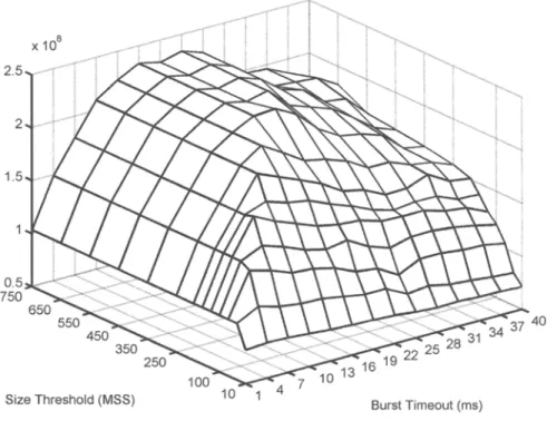
The total goodput for N
=
10 TCP Newreno flows with p=
0.01 and M=
10 is shown in Figure 6 for a range of assembly timeouts and burst size thresholds with a hybrid size/timer-based burst aggregation algorithm. The MSS of the TCP sources are set to 1040 bytes. Receive windows of destination nodes are set to 10000 MSS to avoid the limitation on congestion win-dow increase. In order to study the effect of the burstification timeout on TCP performance, we used the feature of nOBS which allows that TCP ACK packets are not burstified.628 G. GUREL - NOBS: AN Ns2 BASED SIMULATION TOOL FOR PERFORMANCE EVALUATION
FIG 5. - Topology used in simulations.
Topologie utilisée dans les simulations.
For a fixed timeout, the figure shows that goodput increases as the size threshold is increased. However, when the burst size threshold becomes larger than the maximum achie-vable burst size determined by the CUITent timeout, size/timer-based algorithm reduces to timer-based algorithm and goodput does not change. For the large st burst size threshold, the algorithm acts as the timer-based burstifier. On the other hand, since size/timer-based
algo-2.5 2 0.5 750 X 108 650 550 450 350 Size Threshold (MSS) 250 10 13 16 19 22 25 28 31 10 Burst Timeout (ms)
FIG 6. - Total goodput achieved with hybrid size/timer-based burst assembly algorithm (p = 0.01).
Débit applicatif total obtenu avec l'algorithme hybride d'assemblage en rafales fondé sur la taille et la temporisation (p = 0,01).
G. GUREL - NOBS: AN Ns2 BASED SIMULATION TOOL FOR PERFORMANCE EVALUATION 629
rithm becomes size based for a timeout value of infinity, the values with the largest timeout gives an idea about the performance of the size-based algorithm.
For a fixed burst size threshold, the achievable burst size increases with increasing timeout until the current size threshold is reached. We observe that goodput improves with increasing timeout in this region. The effects of high time correlation between delivery and loss events of consecutive packets from a Tep ftow as a result of statistically independent
burst losses are noted as correlation benefits [13]. An important effect of this correlation is the increase in the number of packets sent by a Tep source before noticing a loss event as the
burst size increases and this behavior yields larger congestion windows and higher through-put (Delayed First Loss (DFL) gain) [14]. That is why, for a fixed burst size threshold, the goodput improves as the achievable burst size rises up to the size threshold with increasing timeout. Once the size threshold is reached, however, further increase in the timeout leads to performance deterioration due to additional burst assembly delay (called the delay penalty [13, 14, 15, 16]).
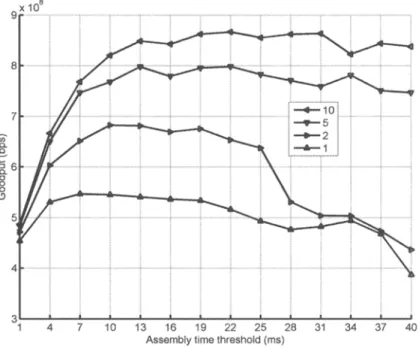
Since the based algorithm achieves the highest goodput, we resort to the timer-based burstification in the rest of the paper for studying the effect of the number of the burs-tifiers on Tep performance. The Tep Newreno performance over a range of time threshold
values are plotted in Figure 7 and Figure 8 for p
=
0.001 and p=
0.01, respectively, for diffe-rent values of the number of burstifiers, M. The remarks that we made for Figure 6 can be observed also in Figure7 and Figure 8. The figures show that as the assembly time threshold is increased, goodput first increases, then starts to decrease. In the region where goodputincreases with timeout, the delay penalty is small and the DFL gain is dominant, therefore increasing the burst size increases the goodput. On the other hand, the improvement provided by the DFL gain saturates after sorne time threshold value and the delay penalty begins to dominate which causes the goodput to deteriorate.
Figure 7 and Figure 8 also demonstrate the significant effect of number of burstifiers on
Tep goodput. We observe that the Tep goodput increases for aIl timeout values as M
increases. Tep ftows sharing an aggregation buffer are affected from successful delivery and
burst loss events together and thus have a tendency to bec orne synchronized. When a burst is lost, Tep ftows that have packets in that burst decrease their congestion windows
simulta-neously. This quick reduction of accessible optical bandwidth results in serious performance degradation. Increasing the number of burstifiers per egress node, we can decrease the level of synchronization between Tep ftows and obtain higher bandwidth utilization as seen in the
plots.
Another important observation is that the rate of deterioration in goodput as time thre-shold is increased depends on loss probability p. When p is large, the congestion window cannot increase to large values due to more frequent burst losses. In this case, the increase in
time threshold does not increase the burst size significantly and the increase in DFL gain with increasing time threshold is not significant. As a resuIt, the goodput decreases more rapidly with increasing time threshold due to the delay penalty. On the other hand, large bursts are generated as the time threshold is increased for small p, and the DFL gain increases with increasing time threshold. This partially compensates the effect of the delay penalty, and the goodput does not degrade much with increasing time threshold.
Tep ftows are classified as slow when only one of their packets is found in a given burst,
fast when their whole congestion window is found in the burst and medium otherwise [13]. The results presented up to this point deal with medium ftows since there is not an upper limit on the congestion window sizes. In order to see the performance of fast ftows and
630 G. GUREL - NOBS: AN Ns2 BASED SIMULATION TOOL FOR PERFORMANCE EVALUATION
~
e
Assembly lime Ihreshold (ms)
FIG 7. - Total goodput with timer-based assembly for N = 10. p = 0.001, M = 1, 2, 5, 10 and Newreno Tep.
~
:; 1.6J
1. 1 1Débit applicatif total avec un assemblage fondé sur la temporisation pour N = JO, p = 0,001, M = l, 2, 5, JO et Newreno TCP.
Assembly lime threshold (ms)
FIG 8. - Total goodput with timer-based assembly for N = 10, p = 0.01, M = 1,2,5, lO and Newreno TCP. Débit applicatif total avec un assemblage fondé sur la temporisation pour N
=
la, p = 0,01,M = 1, 2, 5, JO et Newreno TCP.
G. GUREL - NOBS: AN Ns2 BASED SIMULATION TOOL FOR PERFORMANCE EVALUATION X 108 9,.··"····,,,,··,·· """".".* .• , 8.5 8 7.5 fi) 7 Q. B
a.
6.58
(!) 6 5. 4. 4' , , " , , 1 3 5 7 9 11 13 16 19Assembly lime Ihreshold (ms)
22 25 28
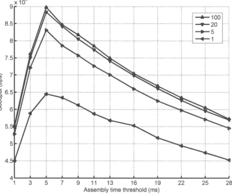
FIG 9. - Total goodput with timer-based assembly for N = 100, p = 0.01, rcv_wnd = 128 MSS,
M = 1,5,20, 100 and Newreno TCP.
Débit applicatif total avec un assemblage fondé sur la temporisation pour N = 100, P = 0,01, rcv_wnd = 128 MSS, M
=
l, 5, 20, 100 et Newreno TCP.631
mine the effect of number of TCP flows better, the network is simulated with N = 100
Newreno fiows with the receive windows set to 128 MSS. Figure 9 shows the results of the simulations for p = 0.01. As the size of the sender's congestion window cannot exceed the receiver's window, DFL gain stays constant at its maximum for large timeouts. Consequently, the effect of delay penalty on goodput can be seen more clearly for large values of timeout and the goodput decreases more rapidly with increasing time threshold. In addition, it is
observed that a relatively low number of buffers may perform close to the per-fiow aggrega-tion case. From Figure 9, we observe that for larger values of N, smaller number of burstifiers is sufficient to obtain performances relatively close to the per-fiow burstification, i.e., M = N. Since the co st of additional burstifiers can be compromised by the improvement in goodput, employing moderate number of buffers with respect to the number of flows constitutes a cost-effective solution.
In order to emphasize the role of number of burstifiers, we computed the optimum
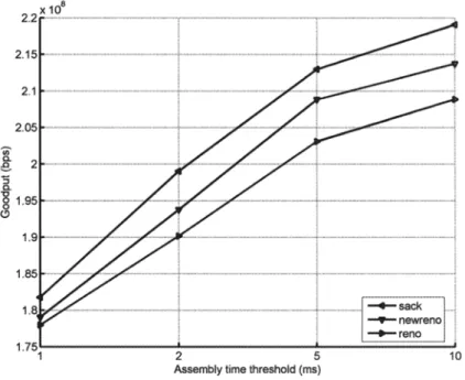
timeout for p = 0.01 and p = 0.001 reaching the maximum goodput for three TCP versions, Newreno, Reno and Sack, for different number of burstifiers, M = 1,2,5 and 10 for N = 10 and M = l, 5, 20 and 100 for N = 100. Figure 10 and Figure Il show the performance of the timer-based algorithm with N = 10 for p=O.OOl and p = 0.01, respectively. Similarly, Figure
632 G. GUREL - NOBS: AN Ns2 BASED SIMULATION TOOL FOR PERFORMANCE EVALUATION
12 and Figure 13 show Tep performance for N = 100. We observe that increasing the number
of burst assemb1ers significantly improves the goodput for aIl three Tep versions since
syn-chronization between Tep flows is reduced as the number of burstifiers is increased.
We a1so observe that although aIl three Tep versions exhibit similar characteristics as the
number of burstifiers is changed, Tep Sack achieves the highest goodput among the three Tep
versions. Sack outperforms the other two versions since it quickly retransmits the lost seg-ments with selective acknowledgeseg-ments. Reno and Newreno have very close performances, however Newreno slightly outperforms Reno.
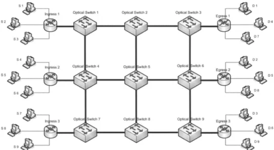
In the second part of the simulations, nOBS is used to simulate an OBS network composed of 3 ingress, 3 egress and 9 core nodes. The topology of this OBS network is shown in Figure 14. In this topology, there are 10 Tep connections between each source-destination pair Si-Di,
i = 1,2, ... , 9, i.e., the total number of Tep connections carried over the OBS network is 90.
Each of the core links has a capacity of 1 Gbps and a propagation delay of 2.5 ms. Each ingress-optical switch and optical switch-egress link has a capacity of 1 Gbps and a propaga-tion delay of 0.1 ms. On the other hand, each access link, i.e., interconnecting source and destination nodes to ingress and egress nodes, has a capacity of 500 Mbps and negligible propagation delay.
The routing table used in these simulations is given below for each source-destination pair (Si-Di, i = 1, ... ,9), where Ik denotes ingress node k, OSL denotes optical switch land Em denotes egress node m.
SI -7 Il -7 OSl -7 OS2 -7 OS3 -7 El -7 Dl
S2 -7 Il -7 OS 1 -7 OS2 -7 OS5 -7 OS6 -7 E2 -7 D2
S3 -7 Il -7 OS 1 -7 OS2 -7 OS5 -7 OS8 -7 OS9 -7 E3 -7 D3
S4 -7 12 -7 OS4 -7 OSl -7 OS2 -7 OS3 -7 El -7 D4
S5 -7 12 -7 OS4 -7 OS5 -7 OS6 -7 E2 -7 D5
S6 -7 12 -7 OS4 -7 OS5 -7 OS6 -7 OS9 -7 E3 -7 D6 S7 -7 I3 -7 OS7 -7 OS4 -7 OS5 -7 OS6 -7 OS3 -7 El -7 D7
S8 -7 I3 -7 OS7 -7 OS4 -7 OS5 -7 OS6 -7 E2 -7 D8
S9 -7 I3 -7 OS7 -7 OS8 -7 OS9 -7 E3 -7 D9
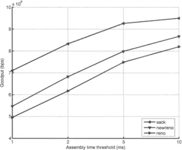
Similar to the first part of the simulation studies, flows destined for each egress no de are burstified using M = 1,2,5,10 burstifiers per egress node in order to investigate the effect of the number of burstifiers on Tep Newreno performance. For each value of M, the
burst assembly time threshold is varied in order to find the maximum goodput achieved by each Tep connection. The average maximum goodput, which is computed by taking
ave-rage over an Tep connections, is shown in Figure 15 for each value of M. The maximum
average goodput increases by more than 20% as the number of burstifiers per egress no de is increased from M
=
1 to 2. Further increase of M from 2 to 10 generates an additional goodput increase of less than 1 %. Since increasing the number of burstifiers at the ingress node results in an increase in cost and complexity, switches with efficient burst assembly and relatively low co st and complexity can be built by considering moderate values of the number of burstifiers.G. GUREL - NOBS: AN Ns2 BASED SIMULATION TOOL FOR PERFORMANCE EVALUATION 633
IV, CONCLUSIONS
nOBS, an ns2 based network simulator for the performance evaluation of Tep over OBS networks is presented. We used nOBS in this paper in order to study the effects of the number of burstifiers used at the edge routers on Tep performance. Simulations show that increasing the number of assemblers per destination reduces the negative effects of synchronization bet-ween Tep ftows occurring as a result of burst losses. We show that Tep goodput is increased significantly when edge routers with multiple burstifiers per destination are used, and the goodput increases as the number of burstifiers increase. This conclusion holds for different Tep versions, different number of ftows, different network topologies and different loss pro-babilities.
Acknowledgements
This work is partially supported by FP6 IST e-photon/ONe+ NOE project and by the Scienti-fic and Technological Research Council of Turkey (TUBITAK) under project 104E047. The authors also would like to thank to Ismail Cirak who has performed sorne of the simulations in this paper.
~
!
X 108 10-~·~~·· 94'
i 1 2 5Assembly lime Ihreshold (ms)
Manuscrit reçu le 16 janvier 2006 Accepté le 28 juin 2006
FIG 10. - Maximum goodput as a function of number ofburstifiers for p = 0.001, N = 10.
Débit applicatif maximal enfonction du nombre d'assembleurs de rafales pour p = 0,001, N = JO.
634 G. GUREL - NOES: AN Ns2 EASED SIMULATION mOL FOR PERFORMANCE EVALUATION 2.15~·· .. '- ... ---2.1 2.05
~
~'8
1.95!-·-..·,_···,-.. ···~-·i~··· .. ~ <.!) 1.9!-···· .. ·· ...'''''_'7-'''''7-us'
,
j i 1 2 5 10Assembly lime threshold (ms)
FIG 1 L - Maximum goodput as a function of number of burstifiers for p = 0.01, N = 10.
Débit applicatif maximal en fonction du nombre d'assembleurs de rafales pour p = 0,01, N = JO.
x 10· 1.8 1.7 ~1.6 ~
11.5
E :l .~ ::i: 1.4 1 1.21 5 20 100 Number of burstifiersFIG 12. - Maximum goodput as a function of number ofburstifiers for p = 0.001, N = 100.
Débit applicatif maximal en fonction du nombre d'assembleurs de rafales pour p = 0,001, N = 100.
G. GUREL - NOBS: AN Ns2 BASED SIMULATION TOOL FOR PERFORMANCE EVALUATION 635 X 10· 9 8.5 'Iii 8 ~
i
g,
7.5 E ::l .~ ~ 7 e1 l l---~---~----======~
5 20 100 Number of burstifiersFIG 13. - Maximum goodput as a function of number ofburstifiers for p = 0.01, N = 100.
Débit applicatif maximal enfonction du nombre d'assembleurs de rafales pour p = 0,01, N = 100.
llt li"!tI ~ 1)4
~ . os
:tK 4
0
'l'f!:>
S3
<!iIIP.
lr"i
FI
r~~_~ __ • ~ ~~ -~ 06FIG 14. - OBS core network topology.
Topologie d'un réseau cœur à commutation optique de rafales.
636 33
l
~ 321
8,
8. 31 ~ ~~
30',.
~ 29 28G. GUREL - NOBS: AN Ns2 BASED SIMULATION TOOL FOR PERFORMANCE EVALUATION
2 3 4 5 6 7 8 9 10
Number of burstifiers
FIG 15. - Maximum average goodput as a function of number of burstifiers. Débit applicatif moyen maximal en fonction du nombre d'assembleurs de rafales.
REFERENCES
[1] LISTANTl (M.), ERAMO (V.), SABELLA (R.), Architectural And Technological Issues For Future Optical Internet Networks, IEEE Communications Magazine, 38, n° 9, pp. 82-92, Sep. 2000.
[2] TURNER (J.), Terabit Burst Switching, 1. High Speed Networks, 8, n° 1, pp. 3-16, 1999.
[3] YAO (S.), XUE (E), MUKHERJEE (B.), Yoo (S.), DIXIT (S.), Electrical Ingress Buffering And Traffic Aggregation For Optical Packet Switching And Their Effect On Tcp-Level Performance in Optical Mesh Networks, IEEE Communications Magazine, 40, n° 9, pp. 66-72, Sep. 2002.
[4] Yoo (M.), QIAO (C.), Optical Burst Switching (OBS) - A New Paradigm for an Optical Internet, Journal of High-Speed Networks, 8, nO 1, pp. 69-84, 1999.
[5] The Network Simulator - ns-2, developed by L. Berkeley Network Laboratory and University of California Berkeley, http://www.isi.edulnsnamlns.
[6] WEN (B.), BRIDE (N.), SHENAl (R.), SIVALINGAM (K.), Optical Wavelength Division Multiplexing (WDM) Network Simulator (Owns): Architecture and Performance Studies, Optical Networks Magazine, 2, n° 5, pp. 16-26, Sep. JOct. 2001.
[7] JEONG (H.), Mo (H.), KANG (M.), OBs-ns: an Ns-2 based Optical Burst Switching (OBS) Simulator, Proceedings of9th Communications and Networking Simulation Symposium, 2-6 April 2006.
G. GUREL - NOBS: AN Ns2 BASED SIMULATION mOL FOR PERFORMANCE EVALUATION 637 [8] Yoo (M.), QIAO (C.), Just-Enough-Time (JET): A High Speed Protoeol for Burst y Traffie in Optieal Networks,
IEEE/LEOS Summer Topieal Meetings, pp. 26-27, Aug. 1997.
[9] ERAMO (V), LISTANT! (M.), PACIFICI (P.), A Comparison Study on the Wavelength Converters Number Needed in Synchronous and Asynchronous All-Optical Switching Architectures, IEEE Journal of Lightwave Teehnology, 21, n° 2, pp. 340-355, Feb. 2003.
[10] XIONG (Y.), VANDENHOUTE (M.), CANKAYA (H.), Control Architecture In Optical Burst-Switched WDM Networks, IEEE Journal on Selected Areas in Communications, 18, n° 10, pp. 1838-1851, Oct. 2000. [11] Xu (J.), QIAO (C.), LI (J.), Xu (G.), Efficient Channel Scheduling Algorithms In Optical Burst Switched
Networks, Proceedings of IEEE Infocom '03, 3, pp. 2268-2278, 30 March-3 April 2003.
[12] Yu (X.), QIAO (C.), LIU (Y.), TCP Implementations and False Time Out Detection in OBS Networks, Proe. of
IEEE INFOCOM'04, 2, pp. 774-784, 7-11 March 2004.
[13] DETTI (A.), LISTANT! (M.), Impact Of Segments Aggregation On TCP Reno Flows In Optical Burst Switching Networks, Proe. IEEE INFOCOM'02, 3, pp. 1803-1812,23-27 June 2002.
[14] Yu (X.), LI (1.), CAO (X.), CHEN (Y.), QIAO (C.), Traffic Statistics and Performance Evaluation In Optical Burst Switched Networks, IEEE/OSA Journal of Lightwave Technology, 22, 12, pp. 2722-2738, Dec. 2004.
[15] Yu (X.), QIAO (C.), LIU (Y.), TOWSLEY (D.), Performance Evaluation OCrep Implementations In OBS Networks, Teeh. Rep. 2003-13, CSE Dept., SUNY, Buffalo, NY, 2003.
[16] GOWDA (S.), SHENAI (R.), SIVALINGAM (K.), CANKAYA (H.), Performance Evaluation Of TCP Over Optical Burst-Switched (OBS) WDM Networks, Proe. IEEE Icc'03, 2, pp. 1433-1437, 11-15 May 2003.