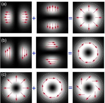
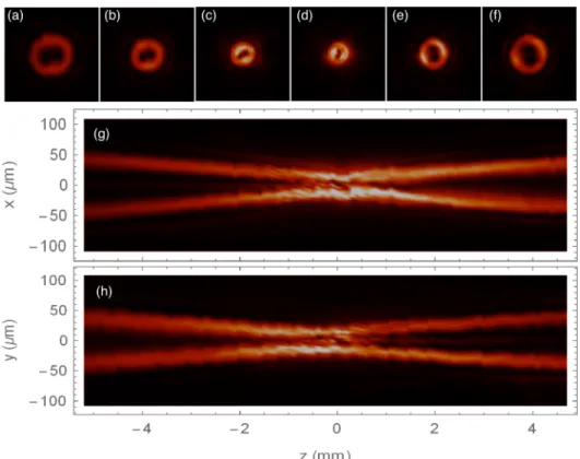
Polar Policryps diffractive structures generate cylindrical vector beams
Tam metin
Şekil
Benzer Belgeler
Kazasker Yusuf Sıtkı Efen dinin oğludur, ilk tahsilini hususi hocalardan yaptıktan sonra İstanbul Hukuk Fakültesine girerek 1903 te mezun oldu.. Sırası ile şu
Romatizmal yak›nma ile baflvuran çocuklar›n ay›r›c› tan›s›nda iki ana veri yararl›d›r: Atefl ve tutulan eklem sa- y›s›.. Afla¤›da bu verilerin birleflimi
Bu iki amaca ulaşmak için toplanan veriler ana- liz edildiğinde, cevaplayıcıların sözleşmede eksik ya da yanlış bilgi sunulması arasında etik problem algılama,
Novel algorithm of maximum power point tracking (MPPT) for variable speed PMSG wind generation systems through model predictive control. In Electrical and Electronics Engineering
To be able to compare the performance of the Alxion generators with the present one by using the developed simple dc model, values such as torque constant (K t ), back-emf constant (K
Keywords: 3D, Art, Avatar, Concrete Poetry, Constrained Writing, Play, Text, Typography, Virtual Worlds, Virtual Reality.. VIRTUAL WORLDS, VIRTUAL REALITY, PLAY
Therefore, a need to conduct an empiric study with students to get data for informing the mathematics education researchers about the situations of teacher practices and
There are several studies about the critical submergence [S = S c at which the lower end (tip) of the air-core vortex just reaches the intake] include those by Denny [1], Anwar
