Protein-releasing conductive anodized alumina membranes for
nerve-interface materials
Sevde Altuntas
a, Fatih Buyukserin
a,b,⁎
, Ali Haider
c, Buket Altinok
d, Necmi Biyikli
c, Belma Aslim
da
Micro and Nanotechnology Graduate Program, TOBB University of Economics and Technology, Ankara, 06560, Turkey
bDepartment of Biomedical Engineering, TOBB University of Economics and Technology, Ankara, 06560, Turkey c
UNAM National Nanotechnology Research Center, Bilkent University, Ankara, 06800, Turkey
d
Department of Biology, Faculty of Science, Gazi University, Ankara, 06500, Turkey
a b s t r a c t
a r t i c l e i n f o
Article history: Received 9 February 2016
Received in revised form 20 April 2016 Accepted 18 May 2016
Available online 19 May 2016
Nanoporous anodized alumina membranes (AAMs) have numerous biomedical applications spanning from bio-sensors to controlled drug delivery and implant coatings. Although the use of AAM as an alternative bone implant surface has been successful, its potential as a neural implant coating remains unclear. Here, we introduce conduc-tive and nerve growth factor-releasing AAM substrates that not only provide the naconduc-tive nanoporous morphology for cell adhesion, but also induce neural differentiation. We recently reported the fabrication of such conductive membranes by coating AAMs with a thin C layer. In this study, we investigated the influence of electrical stimulus, surface topography, and chemistry on cell adhesion, neurite extension, and density by using PC 12 pheochromo-cytoma cells in a custom-made glass microwell setup. The conductive AAMs showed enhanced neurite extension and generation with the electrical stimulus, but cell adhesion on these substrates was poorer compared to the naked AAMs. The latter nanoporous material presents chemical and topographical features for superior neuronal cell adhesion, but, more importantly, when loaded with nerve growth factor, it can provide neurite extension similar to an electrically stimulated CAAM counterpart.
© 2016 Elsevier B.V. All rights reserved.
Keywords: Alumina membranes Nanotechnology Biomaterials PC12 cells Electrical stimulation 1. Introduction
Materials with nanoscale features have attracted a great amount of interest in several scientific fields as energy storage devices[1]and for biomedical applications[2–4]. Anodized alumina membranes (AAMs) are a special class of nanoporous materials that display several desired prospects for biomedical studies, including chemical inertness, biocom-patibility, large surface area, ease of surface functionalization, and tun-able nanotopographic features [5–7]. For instance, an ordered or random pore distribution can be achieved by varying the anodization conditions, which provides control over the porosity, interpore distance, pore diameter, and pore depth of the membrane[8,9]. These properties caused AAMs to emerge as unique substrates for numerous biomedical fields, such as biosensors, drug delivery, immunoisolation, tissue engi-neering, and implant coating[5–7].
The use of AAM as an alternative biomaterial was not surprising be-cause conventional alumina-based ceramics have been used as hip im-plants for over 40 years[10]. Thus, various studies have been conducted to investigate the influence of the AAM topography and surface chemistry
on osteoblastic cell behavior[5–7]. In addition to providing control over morphological and chemical factors in these studies, the nanoporous ma-terial has also been utilized as a reservoir that can release nanoparticles
[11,12], drugs[6], and, growth factors[13]to induce or modulate osteo-blastic cell behavior. Several other cell types involving epithelial, muscle, blood, and neuronal origin have also been investigated against AAM to de-termine their adhesion, proliferation, andfilopodia extension properties
[5]. Studies examining the behavior of neuronal cells interfacing with AAM generally evaluate the influence of membrane topography and sur-face chemistry[14,15]. However, few studies have used AAM-modified silicon[16,17], complementary metal-oxide semiconductor[18], and gold electrode surfaces[19]to improve and control cell signal recording. Similar to the rationale for modifying orthopedic implant surfaces, these studies have demonstrated the potential of AAM-coated neural implants for enhanced cell adhesion and thus increased recording capabilities.
Another important criterion for advanced neural implants is the abil-ity to induce nerve regeneration[20–22]. Several reports have success-fully demonstrated that the application of an electrical stimulus can accelerate neural tissue regeneration. Conducting polymeric scaffolds
[23–25]and carbon nanotubes[26,27]have emerged as novel platforms to attain the desired improvement in neural differentiation. Finally, re-cent studies have demonstrated the induction of neural differentiation via nerve growth factor (NGF)-releasing neural implants[28,29]. The
⁎ Corresponding author at: Micro and Nanotechnology Graduate Program, TOBB University of Economics and Technology, Ankara, 06560, Turkey.
E-mail address:[email protected](F. Buyukserin).
http://dx.doi.org/10.1016/j.msec.2016.05.084
0928-4931/© 2016 Elsevier B.V. All rights reserved.
Contents lists available atScienceDirect
Materials Science and Engineering C
implant surface was coated with biological polymers that electrostati-cally incorporated the growth factor.
In this study, we used conducting AAM (CAAM) substrates as nerve-interfacing membranes. We also report the first attempt to dope nanoporous membranes with NGF, which has been shown to induce neu-ral differentiation in pheochromocytoma-originated PC 12 cells[30,31], the model cell line used in this study. CAAMs with 100 and 250 nm pore diameters were fabricated by coating a thin layer of C on AAMs as de-scribed previously[32]. Our results in PC 12 cells revealed that although electrical stimulation enhanced neurite extension and generation, cell ad-hesion was substantially reduced on CAAMs for both pore diameters. Cell viability and adhesion were the highest for naked AAMs, indicating the importance of surface chemistry on cellular behavior. The topographical influence was also demonstrated by the poor PC 12 adhesion on ultra-smooth alumina substrates obtained by atomic layer deposition (ALD) of alumina on silicon wafers. When AAMs with 100-nm pores were loed with NGF, the membranes not only showloed superior neuronal cell ad-hesion, but also extended neurites comparable to an electrically-stimulated CAAM. Thus, NGF-doped AAMs show potential as neural im-plant coatings, which can provide improved neuronal cell adhesion and induce differentiation at the site of interest.
2. Experimental details
2.1. Fabrication of AAMs and CAAMs
The preparation of naked and conductive AAM substrates is de-scribed briefly, as this fabrication procedure has been previously ex-plained in detail [32]. Al foils (99.999%) were sanded and then extensively washed and sonicated in deionized (DI) water. These foils were then annealed at 450 °C, cooled to room temperature, and electropolished against a Pb cathode for 90 min in an acidic solution composed of H3PO4, H2SO4, and CrO3. Following electropolishing, the
Al foils were subjected to either a single or two-step anodization process
[33]. AAMs with ~250 nm average pore diameters were obtained by a single anodization protocol in which a 160 V anodizing voltage was ap-plied to Al foils in 0.4 M H3PO4electrolyte. Thefinal pore diameter was
adjusted by immersing the AAM in an aqueous chromic acid solution for 22 min. Here, two-step anodization was not performed because the ini-tial oxide layer could not be completely removed despite the use of sev-eral etching solutions. Membranes with ~ 100 nm average pore diameters, however, were obtained by following a two-step anodization procedure. Both anodizations were carried out in 0.3 M oxalic acid elec-trolyte for 18 h. Next, the AAMfilm was dissolved and then regrown in the same electrolyte for 18 h. A pore widening step in dilute H3PO4
so-lution was applied to yield AAMs with 100-nm pores.
AAMs typically form on both faces of the metallic Al foil[34]. In order to utilize these membranes for cell studies, the membranes must be lib-erated from the underlying Al foil. A parafilm layer was used to protect one of the AAM surfaces, while the other AAM face and the Al metal were etched chemically in NaOH and acidic CuCl2solutions,
respective-ly. The protected AAM with a parafilm layer was immersed in hexane and then in DI water to obtain free-standing AAMs[32]. The effect of an electrical stimulus on cellular behavior required the fabrication of conductive substrates. This was accomplished by coating AAMs with a 20-nm-thick C layer using a GATAN Precision Etching & Coating System, which resulted in the production of CAAMs. Extensive electrical, mor-phological, and chemical characterization of CAAMs via atomic force mi-croscopy, X-ray photoelectron spectroscopy, energy-dispersive X-ray spectroscopy, and current-voltage measurements were conducted and as described elsewhere[32]. Image J (Bethesda, MD, USA) was used to calculate average pore diameter and porosity values of the alumina membranes. The roughness values of the membranes were determined by using an atomic force microscope (EZ-AFM, tapping mode, PPP can-tilever, Nanomagnetics, Oxford, UK).
2.2. Cell studies
PC 12 cells were obtained from ATCC (CRL-1721, Manassas, VA, USA) and grown in DMEM standard cell medium (Gibco, Grand Island, NY, USA) containing fetal bovine serum (10%, Invitrogen, Carlsbad, CA, USA), horse serum (10%, Invitrogen), penicillin-streptomycin (1%, Gibco), andL-glutamine (1%, Invitrogen) at 37 °C in a 5% CO2
atmo-sphere. Passage numbers were kept low for all studies and the cell me-dium was changed every other day for cell passaging steps. Sterile chemicals and solutions were used throughout the experiments and fil-tered through 0.22-μm filters (Thermo Fisher Scientific, Waltham, MA, USA) prior to cell experiments. Membranes and homemade glass microwells were sterilized by autoclaving for 45 min at 121 °C (MLS-3751L, Panasonic, Osaka, Japan) and then used under laminarflow cabins. All AAM/CAAM substrates and tissue culture polystyrene (TCPS) controls were coated with type-1 bovine collagen for cell exper-iments unless otherwise mentioned. The collagen (Advanced Biomatrix, Carlsbad, CA, USA) was dissolved in sterile phosphate-buffered saline (Biological Industries, Kibbutz Beit-Haemek, Israel) to afinal concentra-tion of 53.5μg/mL. The membranes were immersed in this solution for 60 min and then washed extensively with phosphate-buffered saline. 2.2.1. Cell viability tests
Cell viabilities for different membranes were evaluated using the WST-1 cell proliferation kit according to the manufacturer's protocol. AAMs and CAAMs (n = 3) with different diameters were cut into ~ 0.25 cm2 pieces and coated with collagen along with the TCPS
microwell controls (n = 3). These membranes were then placed in a 96-well microplate and then incubated with PC 12 cells at a 105cells/
well for 2 or 7 days. Both protocols involved the addition of 20 ng/mL NGF (Life Technologies, Carlsbad, CA, USA) after 24 h for cell differenti-ation; only the 7-day protocol involved changing the NGF-containing cell medium every other day. After incubation, 10μL WST-1 solution was added into each well, mixed for 10 min in a mechanical shaker (Innova 40, Eppendorf, Hamburg, Germany), and then incubated at 37 °C for 2 h in a 5% CO2atmosphere. In order to minimize membrane
absorbance, the solution within the microwells was transferred[35]to a fresh 96-well plate (Corning, Inc., Corning, NY, USA) and absorbance was recorded at 450 nm (Multiscan-Go, Thermo Fisher).
2.2.2. Cell adhesion and neurite measurement studies
Membranes were subjected to cell adhesion studies using a home-made glass microwell setup. The purpose of this step was to create a standard substrate surface area as well as use a standard solution vol-ume for different types of membranes. It also allows the application of an electrical stimulus to CAAMs without direct contact between the electrodes and cell medium. Briefly, 0.3-cm2holes were drilled into
1-cm-thick glass slides and the membrane was sandwiched between this slide and a regular coverslip using parafilm and tissue glue. In order to prevent solvent leakage, additional metallic clips were also used to tighten the assembly. Carbon tapes, where necessary, were also sandwiched within the assembly and provided an electrical contact from CAAM substrates to electrodes without being exposed to any solu-tion. Flat alumina surfaces and TCPS were used as controls. Atomically flat alumina substrates were obtained by coating silicon 〈100⟩ wafers (MicroChemicals GmbH, Ulm, Germany) with 50-nm-thick alumina via ALD (Fiji F200-LL ALD reactor, Cambridge Nanotech, Inc., Waltham, MA, USA). TCPS controls were obtained by cutting ~ 2 cm2flat pieces from 6-well microplates (Corning). Prior to cell studies, all substrates were coated with collagen as described above.
Samples with the same active areas within the glass microwells were incubated with PC 12 cells at 2 × 10⁴cell/mL for 1 day to ensure
cell seeding[36]and then treated with NGF (20 ng/mLfinal concentra-tion) for 36 h for differentiation. The total incubation time was 60 h. Cells on selected CAAM substrates were electrically stimulated by ap-plying 0.1 DC voltage after 57 h of incubation for 1 h[24,37]. At the
end of the 60-h period, samples werefixed for scanning electron mi-croscopy (SEM) imaging and these micrographs were used to extract the number of cells that adhered onto the different substrates as well as the average neurite length and neurite number per cell. Thefixation protocol was conducted by washing the 60-h incubated samples with PBS, followed by immersion into afixative solution composed of 2% glu-taraldehyde and 2% formaldehyde for 90 min[36]. They were then treated with solutions of increasing ethanol content, (50% for 2 min, 75% for 2 min, and 100% for 45 min). Finally, the samples were coated with 10 nm gold by using a sputter coater (GATAN, Pleasanton, CA, USA) for SEM imaging (Quanta 200, FEI, Hillsboro, OR, USA). For some membranes, cell adhesion was qualitatively analyzed byfluorescence imaging; the details are presented in the supplementary content document.
The number of adhered cells on a substrate was calculated by using SEM images from 5 random areas, and for each substrate, 3 independent samples were investigated (n = 3, reported as average number of cells/ mm2). The Image J program was used to measure the average neurite
length on each substrate as well as the average number of neurites per cell, where only neurites longer than the cell diameter (~ 5μm) were considered[38,39]. Here, for samples with branched neurites, only the longest neurite was measured, while for neurites shared by two cells, the neurite was considered to belong to only one cell. To cal-culate differentiation ratios, cells with at least one neurite longer than the cell diameter were considered to be differentiated[38,40]. For statis-tical analysis, unpaired Student's t-test (for two substrate groups) or one-way ANOVA followed by Scheffe's test (to compare more than
two groups) was performed and a value of pb 0.002 was considered sig-nificant (unless otherwise noted).
2.3. NGF doping and release experiments
Selected substrates showing an improved cell response (adhesion, neurite extension) after the standard 60 h procedure (NGF was dis-solved within the cell medium) were also investigated for neural behav-ior with NGF doping. The ex vivo NGF release wasfirst studied for AAMs and CAAMs with 100-nm average pore diameters. These porous sub-strates were treated with a drop of NGF stock solution corresponding to an 80 ng NGF load, and then dried overnight. The membrane pieces (n = 3 for both AAM and CAAM, each having ~ 0.2 cm2loading area)
were then placed in a 96-well microplate containing 200μL DI water as the release media. NGF release was quantified at 6, 24, 48, and 72 h using a commercial NGF ELISA kit (CYT304, EMD Millipore, Billerica, MA, USA) after a calibration curve was constructed according to the manufacturer's suggestions.
The release trend from these ex vivo experiments was used to design the in vitro experiments with NGF-doped membranes. Here, AAMs or CAAMs with 100 nm pore diameters were sandwiched within the glass microwell setup and 20 or 100 ng NGF-containing cell medium was dropped on the faces of these porous substrates. The substrates were dried in a laminarflow cabin and then incubated with 1 mL cell medium (containing 2 × 10⁴cells) that was free of pre-dissolved NGF. The standard 60-h procedure with or without electrical stimulation treatment was then applied to the NGF-loaded membranes, which was followed byfixation, SEM imaging, and analysis of the cellular response.
3. Results and discussion
Free-standing AAMs with ~100 and ~250 nm pore diameters were obtained by anodization of high-purity aluminum in oxalic acid and
Fig. 1. Photographs (a) of free-standing AAM (left) and CAAM (right) samples, and SEM pictures of 100 nm (b) and 250 nm (c) CAAM samples. The scale bars represent 1 cm in (a), 1μm in (b) and 5 μm in (c).
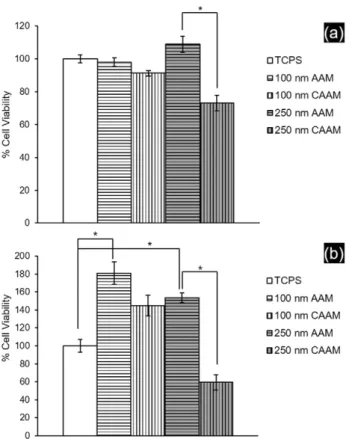
Fig. 2. Cell viability results for the substrates investigated using WST-1 cell proliferation kit for 2 (a) and 7 (b) days of PC 12 incubation. * represents pb 0.002.
phosphoric acid electrolytes, respectively. There are two distinct faces of the resultant membranes, including the barrier side and the solution side. In this study, the solution sides of the membranes were used, the pore diameters of which were adjusted to ~ 100 or ~250 nm by dilute acid pore opening treatments. Moreover, in order to investigate the in-fluence of electrical stimulus, some membranes were rendered conduc-tive by coating with a thin C layer via sputtering. Photographs of the free-standing AAM and CAAM (Fig. 1a) substrates depict the changes in membrane color due to C sputtering. The SEM image of the CAAM sample (Fig. 1b) clearly illustrates the monodispersity of pores, where the average pore diameter was 97.8 ± 2.3 nm. CAAMs with 245.8 ±
21.9 nm average pore diameter (Fig. 1c), however, were obtained by C sputtering on single-step anodized AAMs in phosphoric acid electrolyte in order to investigate the influence of varying topography on the cellu-lar response. Thefirst set of membranes was referred to as the 100 nm AAM/CAAM, while the second set was referred to as the 250 nm AAM/ CAAM. AAM/CAAM samples were not characterized in this study, as de-tailed chemical, electrical, and morphological characterizations have been reported elsewhere[32].
The behavior of PC 12 cells against the porous substrates wasfirst in-vestigated in terms of cell viability. Samples with ~0.2 cm2areas were placed in standard TCPS microwells and viability tests were conducted
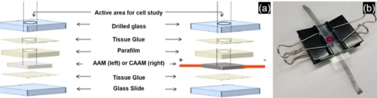
Fig. 3. The constituent layers of the glass microwell assembly (a), and a photograph of a sandwiched CAAM sample showing the cell medium within the glass microwell. The protruding tapes provide connections to the electrodes of the power supply.
Fig. 4. SEM micrographs of PC 12 cells on 100 nm AAM (a), 100 nm CAAM-E (b), 250 nm AAM (c), and 250 nm CAAM-E (d). The insets in (c) show the extensive neurite formation (left) and branching (right) on the electrically-stimulated sample. The scale bars represent 10μm.
after 2 and 7 days of incubation. In all cases, collagen coating was ap-plied to all substrates to obtain standard surface modifications. Without collagen coating, CAAM samples adversely affected the viability, where extensive cell aggregation andfloating were observed on the cell medi-um solution surface as soon as the incubation begun; this was attributed to the hydrophobic nature of the substrates (θc= 101.2° ± 2.2°).Fig. 2a
shows that the AAMs were not toxic, as the viability differences be-tween 100 or 250 nm AAMs with TCPS were not significant (p N 0.05). In addition, for both pore diameters, C coating negatively affected the cell response despite post-collagen modification. It is possible that the presence of a hydrophobic C layer prevented efficient surface collagen coating, resulting in lower viability. Other than the influence of surface chemistry, topography is also thought to affect cellular behavior. For in-stance, better results were obtained for AAMs with 250 nm pore diam-eters (porosity = 62.3 ± 3.4%, roughness = 112.7 ± 10.3 nm), which had higher porosity and roughness compared to 100 nm AAM samples (porosity = 48.6 ± 2.3, roughness = 31.2 ± 4.4 nm). To evaluate this hypothesis, cell viability tests were conducted on AAM samples with ~ 60 nm pore diameters (diameter = 64.7 ± 1.8 nm, porosity = 44.1% ± 1.8%, roughness = 3.6 ± 0.1) and lower viability values were obtained (64.8% ± 7.1%, data not tabulated), confirming the positive in-fluence of porosity and roughness on viability.
Cell viability experiments were also conducted for 7 days of incuba-tion. This set of experiments was carried out because the SEM-based ob-servations indicated considerably improved cell adhesion and growth on 100 and 250 nm AAM substrates compared to TCPS for incubation periodsN2 days (Fig. S1). The result shown inFig. 2b supports this ob-servation, as the 100 and 250 nm AAM samples showed superior viabil-ity trends for 7 days compared to the TCPS control. Topographic factors play an important role in creating this difference. Nanoporous sub-strates have significantly higher surface areas and rougher features for
cell adhesion compared toflat TCPS. During the cell medium changes of long incubation periods (every other day), these nanoporous samples supported cell adhesion to a much greater extend compared to non-po-rous TCPS. Loosely bound cells were washed away from the TCPS sur-face while refreshing the medium, and thus a difference in viability was observed.
However, the trend between the AAM substrates was reversed and the day 7 viability was higher for 100 nm AAM compared to 250 nm AAM. The 100 nm AAM seemed to provide better cell adhesion, al-though it was the less rough and porous AAM. Previous studies reported that the type of anodizing electrolyte may influence the behavior of cells against anodic TiO2membranes[41]. A similar factor may explain our
results, and detailed studies are necessary to confirm this. The negative impact of C coating on the membrane samples was again evident and showed a similar pattern as described above. Both 100 nm and 250 nm CAAM samples showed lower viabilities compared to their non-C-coated counterparts; however, the difference was statistically more significant for the 250 nm AAM/CAAM pair (p = 0.0002 for the 250 nm pair and p = 0.02 for the 100 nm pair).
Detailed analysis of cell adhesion and neurite formation was per-formed for various substrates, as these parameters are important for neural implant applications[20,21]. In order to develop a standard plat-form for AAM/CAAM cell adhesion and neurite studies as well as a setup that incorporates the leads for voltage application to selected CAAMs, a home-made glass microwell assembly was designed (Fig. 3a). Here, 0.3-cm2holes were carefully drilled into 1 cm thick, 2 cm × 2 cm glass
pieces, and the membrane of interest was sandwiched between this piece and a regular glass slide using parafilm, tissue glue, and metallic clips (Fig. 3b). The glass microwell assembly provided a standard sub-strate active area and cell media volume as well as prevented any con-tact between the electrode leads and cell medium. SEM images of the
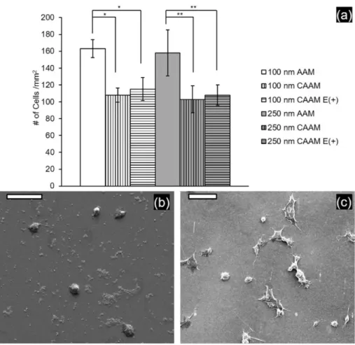
Fig. 5. Bar graphs showing the comparison of adhered cell densities on the 6 substrate groups (a), and representative SEM pictures showing the poor PC 12 cell adhesion and extensive cell debris onflat alumina (b) compared to 100 nm AAM (c). (*p b 0.002, **p b 0.005, and the scale bars of SEM images represent 50 μm.)
substrates incubated with PC12 cells according to the 60 h standard pro-tocol (seeExperimental details) were obtained afterfixation for elec-tron microscopy. Notably, the incubation time, NGF content, and cell passage numbers have large effects on neurite behavior[42](Fig. S2), and the 60 h protocol was used after optimization to obtain well-dis-persed cells showing measurable neurite growth on the substrate of interest.
Representative SEM images of PC 12 cells on the AAM and CAAM samples are shown inFig. 4. We used these images to obtain cell adhe-sion and neurite growth data for 6 different substrates. AAM, CAAM, and electrically-stimulated CAAM (CAAM-E) substrates for both 100 and 250 nm pore sizes, and for each case, 5 random spots from 3 indepen-dent samples (n = 3) were analyzed. Two important observations were made following SEM images; the AAM samples showed a larger number of adhered cells compared to the CAAMs for both pore diame-ters (Fig. 4a, c), and the application of voltage altered the neurite growth pattern for PC 12 cells (Fig. 4b, d). Additionally, the usefluorescence mi-croscopy as a confirming technique for cellular studies was also exam-ined; however, non-specific adsorption of the utilized dyes to the 100 nm AAM/CAAM set (membranes grown in oxalic acid) prevented the use of this method as a common platform for comparison (Fig. S3).
A comparison of the adhered cell populations is illustrated inFig. 5a. Among the substrates investigated, the highest values corresponded to the 100 and 250 nm AAM membranes, with the former slightly higher (pN 0.7); the same trend as shown inFig. 2b was observed. Introduction of C coating altered the surface chemistry such that, despite the pres-ence of an additional collagen coating for all substrates, the prespres-ence of the underlying C layer probably lowered the collagen coating extent, and overall reduction in cell adhesion for both the 100 and 250 nm sets was observed. When the CAAM-E and CAAM substrates were compared, the application of an electrical stimulus did not significantly change the density of adhered cells (pN 0.3 for both sets).
In order to determine the influence of surface morphology on cell adhesion, atomically-flat alumina substrates were fabricated using the ALD method. Here, silicon wafers were coated with a 50-nm-thick alu-mina layer, which had a roughness value of 1.2 nm (Fig. S4). Compared to the 100 nm AAM sample that had an average roughness value of ~ 30 nm, the cell adherence and neurite formation was dramatically lowered for this smooth substrate (Fig. 5b, c). Using the same glass microwell setup, adhered cell density values of 86.1 ± 2.6 cells/mm2
were attained, which is even lower than the poorest cell adhering 250 nm CAAM surface (103.0 ± 16.1 cells/mm2, also the most toxic,
seeFig. 2). Similar responses were observed for osteoblastic[43], epi-thelial[44], and primary neuronal cell types[15]on variousflat alumina substrates, indicating the importance of topography and potential of nanoporous AAM substrates as effective neural biomaterials.
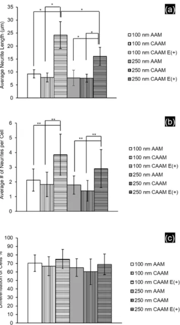
The influence of electrical stimulation on cell adhesion was minimal (Fig 5a); however, stimulation significantly altered the neurite behavior of PC 12 cells.Fig. 6a shows the variation in average neurite lengths and
Fig. 6b shows the number of neurites per cell for the different substrates investigated. In both the 100 nm and 250 nm membrane sets, the appli-cation of DC voltage to the underlying conductive substrate significantly enhanced the average neurite lengths and number of neurites, particu-larly for cells interacting with the 100 nm CAAM-E(+) samples. This tendency has been observed for several other conductive substrates
[45,46]and reveals the neuroregenerative capacity of an applied electri-cal stimulus on neural or neuron-like cells. Although obvious variation occurs with the average number of neurites (Fig. 6b), the ratio of differ-entiated cells changed only slightly with voltage application (Fig. 6c, pN 0.2). Here, the criterion of differentiation was to contain at least one neurite longer than the cell diameter[38,39]. This minimum re-quired phenotype change is mainly determined by the NGF component of cell medium and not the electrical stimulus. The NGF content was the same for all substrates investigated, and thus showed a similar differen-tiation trend (~70%).
An interesting feature of nanoporous membranes is their intrinsic porous volume, which can be utilized for loading molecules involving drugs[6], proteins[13], and nanoparticle formulations[11,12]. To dem-onstrate their potential as drug eluting/differentiation-inducing neural implant interfaces, 80 ng NGF was doped in select samples showing the highest cell adherence (100 nm AAM) and neurite extension results (100 nm CAAM (E +)). The cellular responses for these loaded sub-strates were then compared to standard treatment, in which NGF was pdissolved in the cell media. Prior to this comparison, ex vivo NGF re-lease wasfirst confirmed from the nanoporous membranes without any voltage application (i.e. using NGF-loaded 100 nm AAM and CAAMs).
Fig. 7shows that for both substrates with ~100 nm pore openings, proximately 20% of the loaded protein was released after 60 h and ap-proximately 25% NGF was released after 72 h. This slow release is an advantage for many applications that require long releasing platforms and is thought to arise from the rather large size of the protein[6,47].
In vitro studies of NGF-releasing membranes were conducted using the glass microwell assembly (V = 1 mL) with two different NGF load-ing scenarios. One sample was loaded with 100 ng NGF so that after 60 h, it would have similar NGF content as the standard NGF treatment (20% of 100 ng/mL = 20 ng/mL = [NGF]standard), and a second sample
with 20 ng NGF due to potential adverse effects caused by the high
Fig. 6. Bar graphs showing the average neurite lengths (a), average number of neurites per cell (b) as well as percent of differentiated cells (c) on the 6 substrate groups with or without electrical stimulus (*pb 0.002, **p b 0.005).
NGF concentration. This hypothesis was supported by the data shown in
Fig. 7b and c, where poor cell adhesion and clogged nanopores were ob-served after 60 h of cell incubation for the 100 ng NGF-loaded substrate. The relatively low cell adhesion and differentiation observed on this membrane (Fig. 7b) compared to the standard NGF-treated nanoporous 100 nm AAM (Fig. 5c) indicates that the protein layer inhibited the pos-itive influence of the nanoporous AAM morphology.
The PC12 cells on 20 ng NGF-loaded AAM and CAAMs are shown in
Fig. 8, where the latter substrate was electrically stimulated for 1 h. Sim-ilarly to the previous samples, the naked AAM substrate allowed a larger number of cells to adhere on the nanoporous surface compared to the C-coated counterpart (Fig. 8a, b). In both cases, the nanopores were not blocked because of the lowered NGF load (Fig. 8c,d), and thus chemistry rather than the topography played a critical role in cell adhesion.Fig. 8e and f presents a quantitative comparison of cell behavior between these NGF-loaded samples and the 100 nm CAAM-E+ substrate that showed the most neurite extension under standard NGF treatment. The loaded 100 nm AAM showed the highest cell adhesion, as expected (149.5 ± 20.7 cells/mm2), and adhered cell density was similar to the reported
number inFig. 5a (163.0 ± 10.7 cells/mm2for 100 nm AAM).
NGF doping had negative effects on electrically-stimulated 100 nm CAAM substrates, as both the cell adhesion and neurite lengths were lower for protein-loaded samples compared to CAAMs subjected to standard treatment. On the AAM substrate, however, NGF loading great-ly enhanced neurite extension, with an average neurite length that was nearly tripled compared to standard NGF-treated 100 nm AAM (Fig. 6a) and approaching the average of electrically-stimulated 100 nm CAAM with standard NGF treatment (Fig. 8f, pN 0.05). The 100 nm AAO
substrate that originally showed the highest cell adhesion retained its chemical and morphological properties when doped with the proper amount of NGF, providing not only optimum cell adhesion but also enhancing neurite extension similarly to an electrically-stimulated conductive counterpart. The increased local NGF present in the vicinity of the protein-releasing nanoporous alumina surface can be the underlying reason as this parameter has been shown to play an important role in the formation and extension of neurites from PC 12 cells[36].
4. Conclusion
In this study, the behavior of PC 12 cells against naked or conductive nanoporous alumina substrates was compared in terms of various pa-rameters including cell viability, adhesion, and neurite length. AAMs with 100 and 250 nm nominal pore diameters were fabricated and then coated with a thin layer of C to obtain CAAMs. Naked AAMs were not toxic to the cells, and improved cell adhesion was observed on the 100 and 250 nm AAM samples. Both surface chemistry and topography played important roles in this trend as shown by the much poorer cell adhesion observed on nanoporous C-coated CAAMs as well as alumina coated smooth Si wafers. However, the average neurite length and number of neurites per cell greatly increased when an electrical stimu-lus was applied to both the 100 and 250 nm CAAM conductive sub-strates. Two samples showing the highest cell adhesion and neurite extension results were used for NGF loading. The results suggest that when the loading conditions are optimized, NGF-loaded 100 nm AAM substrates can provide an ideal platform for PC 12 adhesion. This
Fig. 7. Demonstration of ex vivo NGF release from 100 nm AAM/CAAM substrates using a commercial ELISA kit (a), and SEM micrographs showing poor cell adhesion (b) and blocked nanopores (c) for 100 nm AAM substrate loaded with 100 ng NGF. The scale bars represent 100μm in (b), and 1 μm in (c).
substrate can also enhance neurite extension comparable to an electri-cally-stimulated CAAM. Improved cell adhesion and capability to induce differentiation are desired properties for neural implants andfindings of the current investigation indicate that a neural implant with a thin, pro-tein-doped nanoporous alumina interface can be used to achieve both of these goals. For instance, anodization of thermally-evaporated
aluminum can yield such oxide coatings on electrodes, the thickness of which can be tuned without significantly altering electrode imped-ance. The development of such electrode systems (e.g. cortical neural prosthesis electrodes or deep neurostimulation electrodes like DBS™) is currently being pursued as advanced drug-eluting biomaterials with improved recording/stimulating capabilities.
Fig. 8. Low and high magnification SEM micrographs of PC 12 cells on 20 ng NGF loaded AAM (a, c) and CAAM (b, d) substrates, respectively.Fig. 8c and the inset in 8d show that the pores are not blocked after protein loading. The cell adhesion (e) and average neurite length bar graphs (f) demonstrate the cell behavior difference on the indicated substrates with standard NGF treatment or NGF loading. One-way ANOVA followed by Scheffe test was applied for statistical comparison. *pb 0.05. The scale bars represent 100 μm in (a) and (b), and 5 μm in (c) and (d).
Acknowledgement
This project was supported by The Scientific and Technological Re-search Council of Turkey, Grant No: 111M686.
Appendix A. Supplementary data
Supplementary data to this article can be found online athttp://dx. doi.org/10.1016/j.msec.2016.05.084.
References
[1] Q. Zhang, E. Uchaker, S.L. Candelaria, G. Cao, Nanomaterials for energy conversion and storage, Chem. Soc. Rev. 42 (2013) 3127–3171.
[2] V. Labhasetwar, D.L. Leslie-Pelecky, Biomedical Applications of Nanotechnology,first ed. Wiley-Interscience, 2007.
[3] Z. Aguilar, Nanomaterials for Medical Applications,first ed. Elsevier Publications, 2012.
[4] R.A. Petros, J.M. DeSimone, Strategies in the design of nanoparticles for therapeutic applications, Nat. Rev. Drug Discov. 9 (2010) 615–627.
[5] D. Bruggemann, Nanoporous aluminium oxide membranes as cell interfaces, J. Nanomater. 460870 (2013).
[6] A.M.M. Jani, D. Losic, N.H. Voelcker, Nanoporous anodic aluminium oxide: advances in surface engineering and emerging applications, Prog. Mater. Sci. 58 (2013) 636–704.
[7] C.J. Ingham, J. ter Maat, W.M. de Vos, Where bio meets nano: the many uses for nanoporous aluminum oxide in biotechnology, Biotechnol. Adv. 30 (2012) 1089–1099.
[8] R.C. Furneaux, W.R. Rigby, A.P. Davidson, The formation of controlled porosity mem-branes from anodically oxidized aluminum, Nature 337 (1989) 147–149.
[9] K. Nielsch, J. Choi, K. Schwirn, R.B. Wehrspohn, U. Gosele, Self-ordering regimes of porous alumina: the 10% porosity rule, Nano Lett. 2 (2002) 677–680.
[10]P. Boutin, P. Christel, J.M. Dorlot, A. Meunier, A. Deroquancourt, D. Blanquaert, S. Herman, L. Sedel, J. Witvoet, The use of dense alumina-alumina ceramic combina-tion in total hip-replacement, J. Biomed. Mater. Res. 22 (1988) 1203–1232.
[11]A.R. Walpole, Z.D. Xia, C.W. Wilson, J.T. Triffitt, P.R. Wilshaw, A novel nano-porous alumina biomaterial with potential for loading with bioactive materials, J. Biomed. Mater. Res. A 90A (2009) 46–54.
[12]M.S. Aw, S. Simovic, J. Addai-Mensah, D. Losic, Polymeric micelles in porous and nanotubular implants as a new system for extended delivery of poorly soluble drugs, J. Mater. Chem. 21 (2011) 7082–7089.
[13] B.-Y. Lee, C.-W. Li, G.-J. Wang, Nanoporous anodic aluminum oxide tube encapsulat-ing a microporous chitosan/collagen composite for long-actencapsulat-ing drug release, Biomed. Phys. Eng. Express 1 (2015) 045004.
[14] F. Haq, V. Anandan, C. Keith, G. Zhang, Neurite development in PC12 cells cultured on nanopillars and nanopores with sizes comparable withfilopodia, Int. J. Nanomedicine 2 (2007) 107–115.
[15] W.K. Cho, K. Kang, G. Kang, M.J. Jang, Y. Nam, I.S. Choi, Pitch-dependent acceleration of neurite outgrowth on nanostructured anodized aluminum oxide substrates, Angew. Chem. Int. Ed. 49 (2010) 10114–10118.
[16] B. Wolfrum, Y. Mourzina, F. Sommerhage, A. Offenhausser, Suspended nanoporous membranes as interfaces for neuronal biohybrid systems, Nano Lett. 6 (2006) 453–457.
[17] S. Prasad, J. Quijano, Development of nanostructured biomedical micro-drug testing device based on in situ cellular activity monitoring, Biosens. Bioelectron. 21 (2006) 1219–1229.
[18] A.H.D. Graham, C.R. Bowen, J. Robbins, J. Taylor, Formation of a porous alumina elec-trode as a low-cost CMOS neuronal interface, Sensors Actuators B Chem. 138 (2009) 296–303.
[19] M. Wesche, M. Hueske, A. Yakushenko, D. Brueggemann, D. Mayer, A. Offenhaeusser, B. Wolfrum, A Nanoporous Alumina Microelectrode Array for Func-tional Cell-Chip Coupling, Nanotechnology 23, 2012.
[20] W. He, R.V. Bellamkonda, Nanoscale neuro-integrative coatings for neural implants, Biomaterials 26 (2005) 2983–2990.
[21] L. Vaysse, A. Beduer, J.C. Sol, C. Vieu, I. Loubinoux, Micropatterned bioimplant with guided neuronal cells to promote tissue reconstruction and improve functional re-covery after primary motor cortex insult, Biomaterials 58 (2015) 46–53.
[22] B. Mammadov, M. Sever, M.O. Guler, A.B. Tekinay, Neural differentiation on synthet-ic scaffold materials, Biomed. Sci. 1 (2013) 1119–1137.
[23] S.K. Seidlits, J.Y. Lee, C.E. Schmidt, Nanostructured scaffolds for neural applications, Nanomedicine 3 (2008) 183–199.
[24]C.E. Schmidt, V.R. Shastri, J.P. Vacanti, R. Langer, Stimulation of neurite outgrowth using an electrically conducting polymer, Proc. Natl. Acad. Sci. U. S. A. 94 (1997) 8948–8953.
[25]J.W. Xie, M.R. MacEwan, A.G. Schwartz, Y.N. Xia, Electrospun nanofibers for neural tissue engineering, Nanoscale 2 (2010) 35–44.
[26]W.-T. Su, Y.-A. Shih, Nanofiber containing carbon nanotubes enhanced PC12 cell proliferation and neuritogenesis by electrical stimulation, Bio-Med. Mater. Eng. 26 (2015) S189–S195.
[27] J.Y. Hwang, U.S. Shin, W.C. Jang, J.K. Hyun, I.B. Wall, H.W. Kim, Biofunctionalized car-bon nanotubes in neural regeneration: a mini-review, Nanoscale 5 (2013) 487–497.
[28] J.-Y. Lee, S.M. Kim, M.-J. Kim, J.H. Lee, Controlled release of nerve growth factor from heparin-conjugatedfibrin gel within the nerve growth factor-delivering implant, J. Kor. Assoc. Oral and Maxillofac. Surg. 40 (2014) 3–10.
[29] Z.L. Zhang, Q.Q. Li, L. Han, Y.H. Zhong, Layer-by-layerfilms assembled from natural polymers for sustained release of neurotrophin, Biomed. Mater. 10 (2015) 9.
[30]D.G. Drubin, S.C. Feinstein, E.M. Shooter, M.W. Kirschner, Nerve growth factor in-duced neurite outgrowth in PC12 cells involves the coordinate induction of micro-tubule assembly and assembly promoting factors, J. Cell Biol. 101 (1985) 1799–1807.
[31]J. Samal, D.B. Hoban, C. Naughton, R. Concannon, E. Dowd, A. Pandit, Fibrin-based microsphere reservoirs for delivery of neurotrophic factors to the brain, Nanomedicine 10 (2015) 765–783.
[32] S. Altuntas, F. Buyukserin, Fabrication and characterization of conductive anodic alu-minum oxide substrates, Appl. Surf. Sci. 318 (2014) 290–296.
[33] H. Masuda, K. Fukuda, Ordered metal nanohole arrays made by a 2-step replication of honeycomb structures of anodic alumina, Science 268 (1995) 1466–1468.
[34] F. Buyukserin, C.R. Martin, The use of reactive ion etching for obtaining "free" silica nano test tubes, Appl. Surf. Sci. 256 (2010) 7700–7705.
[35] I.C. Chung, C.-W. Li, G.-J. Wang, The Influence of Different Nanostructured Scaffolds on Fibroblast Growth, Science and Technology of Advanced Materials 14, 2013.
[36]M. Marcus, H. Skaat, N. Alon, S. Margel, O. Shefi, NGF-conjugated iron oxide nano-particles promote differentiation and outgrowth of PC12 cells, Nanoscale 7 (2015) 1058–1066.
[37] G. Kang, R. Ben Borgens, Y.N. Cho, Well-ordered porous conductive polypyrrole as a new platform for neural interfaces, Langmuir 27 (2011) 6179–6184.
[38]C. Simitzi, E. Stratakis, C. Fotakis, I. Athanassakis, A. Ranella, Microconical silicon structures influence NGF-induced PC12 cell morphology, J. Tissue Eng. Regen. Med. 9 (2014) 424–434.
[39] A. Yang, Z. Huang, G. Yin, X. Pu, Fabrication of aligned, porous and conductivefibers and their effects on cell adhesion and guidance, Colloids Surf. B: Biointerfaces 134 (2015) 469–474.
[40] V. Malkoc, D. Gallego-Perez, T. Nelson, J.J. Lannutti, D.J. Hansford, Controlled neuro-nal cell patterning and guided neurite growth on micropatterned nanofiber plat-forms, J. Micromech. Microeng. 25 (2015).
[41] X.L. Zhu, J. Chen, L. Scheideler, R. Reichl, J. Geis-Gerstorfer, Effects of topography and composition of titanium surface oxides on osteoblast responses, Biomaterials 25 (2004) 4087–4103.
[42] P.B. Hollenbeck, J, Methods in Cell Biology, in: Neurons: Methods and Applications for the Cell Biologist, Academic Press, 2003 271.
[43] K.C. Popat, E.E.L. Swan, V. Mukhatyar, K.I. Chatvanichkul, G.K. Mor, C.A. Grimes, T.A. Desai, Influence of nanoporous alumina membranes on long-term osteoblast re-sponse, Biomaterials 26 (2005) 4516–4522.
[44]S.H. Chung, S.J. Son, J. Min, The Nanostructure Effect on the Adhesion and Growth Rates of Epithelial Cells with well-Defined Nanoporous Alumina Substrates, Nano-technology 21, 2010.
[45] L. Wang, Q. Huang, J.-Y. Wang, Nanostructured polyaniline coating on ITO glass pro-motes the neurite outgrowth of PC 12 cells by electrical stimulation, Langmuir 31 (2015) 12315–12322.
[46]H.-W. Liu, W.-C. Huang, C.-S. Chiang, S.-H. Hu, C.-H. Liao, Y.-Y. Chen, S.-Y. Chen, Arrayed rGOSH/PMASH microcapsule platform integrating surface topography, chemical cues, and electrical stimulation for three-dimensional neuron-like cell growth and neurite sprouting, Adv. Funct. Mater. 24 (2014) 3715–3724.
[47] D.W. Gong, V. Yadavalli, M. Paulose, M. Pishko, C.A. Grimes, Controlled molecular re-lease using nanoporous alumina capsules, Biomed. Microdevices 5 (2003) 75–80.