Master thesis
Master of Science in Manufacturing Technology
Investigation of longitudinal distortion occurring
in Acrylonitrile butadiene styrene copolymer
(ABS) extrusion profiles
by
B.Sc. Sercan Karakas Matr.-Nr. 1561011101
Supervisors:
Prof. Dr.-Ing. Markus Stommel
Investigation of longitudinal distortion occurring in acrylonitrile-butadiene-styrene copolymer (ABS) extrusion profiles
Submitted on: 08.02.2019
Institut für Ingenieur- und Naturwissenschaften
Master of Manufacturing Technology Dr. Mehmet İpekoğlu
Şahinkaya Cad. 86 34820 Beykoz / Istanbul Tel.+90(216)3333000 Fax.+90(216)3333038
Roma Plastik EGGER Ltd Gebze Plastikçiler OSB, Gebze, 41400 Kocaeli, Turkey
List of tasks
- Description of the problem in detail
- Reviewing the further works and their results
- Observation of extrusion process and post-processes
- Choosing the parameters to be investigated regarding banana problem for each process
- Making the test plans including these choosen parameters - Conducting these tests producing samples and labeling them - Making the banana measurements for each sample
- Analyzing the test datas statistically, obtaining the results showing the influence of each parameter on the banana problem - According to these results, making standardisations,
configurations and process change if need to minimize the banana problem
Summary
In this study, the longitudinal distortion of acrylonitrile-butadiene-styrene (ABS) extrusion profiles was investigated experimentally. The longitudinal distortion is a problem which is seen mostly in extrusion profiles. Since it causes deformed edge bands which look like a banana, this is known as banana problem. It creates undesired situation for customers and, consequently, for the producer. The aim of this work is to investigate this problem depending on chosen parameters by making tests and analyzing the results in order to find possible reasons, and then, to minimize or avoid the problem.
The general polymer classifications and characteristics of ABS which could be related to the longitudinal distortion problem were explained in detail. The extrusion process and its units were examined by focusing this problem. In experimental works, the entire extrusion line was observed, then, some processes were investigated by making cutting, winding and tensile tests. During observation, the parameters which could have an effect on banana shape were decided. With these parameters, test plans were created. Afterwards, these tests were conducted, then, the results were analyzed with the help of design of experiments (DOE). According to results, some causes were found. Some improvements such as alternating winding process were made in the extrusion line accordingly. Influences of studied parameters on the longitudinal distortion were shown and interpreted for further studies.
Table of contents
1 Introduction ... 1
1.1 Definition of the problem ... 1
1.2 Aim of the study ... 3
1.3 Procedure of the study ... 3
2 Polymer Science ... 5
2.1 Introduction to polymer science ... 5
2.2 Polymer classifications ... 6
2.3 Acrylonitrile-butadiene-styrene (ABS) ... 8
2.4 Characteristics of ABS ... 10
2.4.1 Glass transition temperature ... 10
2.4.2 Viscoelasticity... 14
2.4.3 Shape memory effect ... 17
2.4.4 Molecular orientation ... 20
2.4.5 Residual stress formation ... 22
3 Extrusion: Polymer Processing Technology ... 25
3.1 Fundamentals of extrusion technology ... 25
3.1.1 Extruder unit ... 25
3.1.2 Calendering ... 27
3.1.3 Cooling water bath ... 28
3.1.4 Puller ... 29
3.1.5 Lacquer, UV and primer stations ... 29
3.1.6 Slitting station ... 30
3.1.7 Winding station... 31
4 Introduction to Design of Experiments ... 34
5 Experimental Works ... 36
5.1 Cutting experiment ... 36
5.1.1 Cutting test procedure ... 36
5.1.2 Cutting test results ... 38
5.2 Winding experiments ... 42
5.2.2 Winding test.1 results ... 45
5.2.3 Procedure of winding test.2... 47
5.2.4 Winding test.2 results ... 49
5.2.5 Procedure of winding test.3... 52
5.2.6 Winding test.3 results ... 53
5.2.7 Procedure of winding test.4... 53
5.2.8 Winding test.4 results ... 55
5.2.9 Procedure of winding test.5... 57
5.2.10 Winding test.5 results ... 58
5.2.11 Procedure of winding test.6... 59
5.2.12 Winding test.6 results ... 61
5.3 Tensile testing according to ASTM D882 ... 62
6 Results & Discussion... 65
7 Summary & Outlook ... 73
8 Nomenclature ... 75
9 Bibliography ... 76
Appendix
A1 Cutting test results ... 1A2 Winding test results ... 3
A2.1 Test.1 ………..3 A2.2 Test.2 ………..6 A2.3 Test.3 ………..8 A2.4 Test.4 ………..9 A2.5 Test.5 ………13 A2.6 Test.6 ………16
1
Introduction
1.1 Definition of the problem
Extrusion is a basic plastic processing method in which a polymer material is melted. Then, this molten plastic is formed by pushing through a die with the help of high pressure created by the screw. Common polymers, such as high-density polyethylene (HDPE), low-density polyethylene (LDPE), polypropylene (PP), polystyrene (PS), polymerizing vinyl chloride (PVC) and acrylonitrile-butadiene-styrene (ABS) which is examined in this study, are used as raw material in the extrusion process. ABS is a widely used copolymer which is a combination of acrylonitrile, butadiene and styrene. Its important characteristics are hardness and rigid structure coming from Acrylonitrile-styrene copolymer, and ductility resulted by Butadiene polymer.
Longitudinal distortion is a commonly encountered problem in extrusion profiles with continuous cross-section. This problem will be later called ‘banana problem‘ because of its resemblance, will be studied in detail.
Edge bandings, which are mostly demanded for furniture business, are used in home decoration and furniture. It is bonded to the sharp edges of chipboard or medium-density fibreboard (MDF) for safety and aesthetic concerns. They can be seen in the edge of tables and cabinets, as seen in Figure 1-1. This bonding process is done by gluing or laser bonding. Edge bandings, which consist of polymer materials, are manufactured in thickness ranging from 0,4 mm to 3,0 mm, in width ranging from 12 mm to 100 mm, by extrusion process. After the extrusion process, post-extrusion operations are done depending on use and material of the edge banding. For production of ABS polymer edge bandings which will be studied in detail later on, the post-extrusion processes in sequence are embossing, cooling, haul off, printing, primer, lacquer, in-line cutting in which 100 mm width extruded part is slit to 4 equal width edge bandings, and winding processes.
Figure 1-1: Sample of ABS edge band
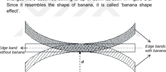
It was observed that the dimensions of the edge bandings change both short after the production, as well as in long term. Especially in edge bandings from 0,8 mm to 1,0 mm in thickness, these changes were observed bowing to up or down as seen in Figure 1-2. Since it resembles the shape of banana, it is called ‘banana shape effect’.
Figure 1-2: Top view of edge bandings with longitudinal distortion in both directions As well as the decor of edge banding, its dimension has also visual significance on home decoration. For dimension control, edge bending sample with 2 meter length is taken from the product just after the production. After it is fixed from both ends in the same direction, the distance, d, between the middle point of the sample and the point, where it is supposed to be in the same direction with fixed ends, is measured. Sample edge band on the measurement table can be seen in Figure 1-3. The important point here is that both ends of edge band have to be relaxed instead of being stretched during measurement.
d
Edge bands with banana Edge band
Figure 1-3: Banana-shaped 2m edge band sample and measurement table
As in all measurement techniques, there is a tolerance value which was decided by the customers here. While the edge bandings, which have d ≤12 mm dimensional deviation, are acceptable, those, which have bigger than 12 mm, are not acceptable. These edge bandings cause a big problem during bonding of edge bandings to the boards or furniture. Since the furnitures have straight edge, laser bonding or gluing, which are bonding techniques used by customers, can be only applied straight. However banana-shaped edge band can not be bonded to the straight edge of the furniture, because it is curved. So to say, this problem creates very undesired situation for furnishers and carpenters. In that case, they would be all scrap.
1.2 Aim of the study
The purpose of this study is to understand this problem by investigating and analyzing the processes which can be a cause for this problem, then, to find possible reasons for minimizing or avoiding the problem. In this case, the company would get a knowledge about ABS polymer behaviour to take precautions by making improvements in order not to have it in the future.
Since the banana shaped edge bands can not be applied to the straight surfaces, they become scrap. When the scrap volume increases, consumption of plastic increases, use of production sources as well. The loss of company increases in total incrementally. Owing to avoiding or minimizing by keeping this problem in tolerance range, the company can minimize the scrap and loss.
1.3 Procedure of the study
Before starting, actual extrusion process is divided into three steps, Winding, Cutting and Extrusion steps to make the study easy searchable by going step-by-step. Then actual process conditions are firstly observed for each step. During observation, the parameters which could have an effect on banana shape are decided. With these
parameters, test plans are created. Afterwards, these test plans are conducted. After the tests, the results are analyzed. Within this period, for creating test plan, making and analysing the tests, Design of experiments (DOE) is used with the use of Minitab software.
With the statistical analysis of results, the effects of parameters are seen numerically. After the test, the best result are chosen by comparing the effects of parameters. In the further tests, this best case is used to minimize the effect of that parameter. According to the results, optimum process conditions are implemented to minimize the banana effect.
2
Polymer Science
2.1 Introduction to polymer science
Polymers have been in the nature from the beginning of the universe, as a molecule form in animals, plants or any living organisms. However, they have being understood in last decades with improving science. As their nature has been understood, they have been developed by humans. Thus, new polymeric materials have been started to being used in human life, and their use is increasing day by day (Ebewele, 2000).
The first polymer found in natural products, like cotton, proteins and cellulose in trees have being used more in different areas, since they are advantageous compared to traditional materials, low cost, improvable in performance and safety, low weight, corrosion resistance and good insulation and conduction properties (Akay, 2012).
Polymer is a greek word meaning many (poly) units (mere). So basically, it is a large molecule which is called polymer molecule or macromolecule emerging from the repetition of small chemical units, called monomer that can be a single atom or a small group of atoms(Ghosh, 2006). As an example, the configuration of monomer (left) and polymer (right) can be seen in Figure 2-1.
Figure 2-1: Styrene (monomer) and polystyrene (polymer) [Ebewele, 2000]
After opening the double bond of styrene, it becomes open to be linkable with other styrenes. Then n- number styrene are linked up each other by covalent bonding with the help of heat, light or a special catalyst as an initiator. As a result of bonding the repeat units, can be seen in above on right, the polystyrene which has degree of polymerization of n is obtained (Ghosh, 2006). This chain can be seen in Figure 2-2.
Figure 2-2: Polymer molecule model [Ghosh, 2006]
If we talk about chain, the length should be discussed. Here the term Length to Diameter (L/D) is used to specify the difference between polymers. This difference is in only physical and mechanical properties. Thermomechanical conditions determine the degree of entanglement. In case of melting temperature, the chain could be more straight and having more long length (Ghosh, 2006).
2.2 Polymer classifications
Polymers have been categorized in different ways. These categories are based on the origin of the polymer, the polymer structure, polymerization mechanism, molecular forces, the monomer type in the structure, thermal response and the composition.
There are three kinds of polymers based on the origin; natural, semisynthetic and synthetic polymers. Natural polymers are found naturally existing in plants or animals as proteins, cellulose, enzymes, natural rubber and starch etc. Semisynthetic polymers is obtained from natural sources but applied chemical treatment before use, like vulcanized rubber, some cellulosic polymers. The polymers which were produced in laboratories by humans due to needs are called synthetic polymers such as ABS (Ghosh, 2006).
According to the chain structure, polymers are classified into three groups, linear, branched and cross-linked structures, as in Figure 2-3. Linear structure is having long chain in which all monomers are linked to each other without branches. They have higher melting point and density. Branched structure is having linear chain with branches in which monomers are linked to each other in different length. Due to these branches, they have lower density and melting point. Cross linked structure is a complex structure in which monomers are linked to each other in three dimensional network structure. These polymers are hard and brittle (Ghosh, 2006).
Figure 2-3: Linear (left), branched (middle), cross linked (right) [Ebewele, 2000] Intermolecular forces which pull the molecules to each other are determined by chemical bonds between molecules. These chemical bonds are divided into two bonds depending on valence electrons. In primary valence bonding, because the atoms are kept together to create molecules by using their valence electrons, they are strong bonds which are ionic, metallic and covalent bonds. The atoms in polymers use mostly covalent bonds. In secondary bonding, the valence electrons are not used, because all electrons were used to form molecules. However, these molecules pull to each other because of cohesive aggregation. These are called secondary valence forces, known as van der Waals, dipole and hydrogen bonds which are weaker than primary bonds. Both are created in molecule formation. To have maximum strength of these bonds, the effect of secondary bonds must be increased by coming all molecules close to each other (Ebewele, 2000). These intermolecular forces contribute defining the mechanical properties of plastics, such as tensile strength, stretchability and tension (Ghosh, 2006).
There are two polymers when they are heated giving different response. Thermoplastics are softening and melting, and can be easily molded. When they are cooled, they become hardened. They are reusable and recyclable. Heating and cooling can be applied many times reversibly. However, thermosettings soften, then change chemically irreversibly when they are heated. Thermoplastics are mostly linear and branched polymers which are soluble and fusible, such as ABS, while thermosettings are cross-linked polymers which are insoluble and infusible (Ghosh, 2006).
According to their composition, polymers are divided into two groups, homopolymer and copolymer. Homopolymers are having same repeating units in their molecules. Copolymers are created by adding different repeating units. ABS is a copolymer which is combined of three monomers. They are having more than one repeating unit in their molecule. Copolymers have four subgroups, random copolymer which the repeating units are found randomly on the chain, alternating copolymer that the repeating units are found ordered, block copolymer
that has repeating units ordered blocks, graft copolymer which one repeating unit is branched onto other repeating unit (Ebewele, 2000). Molecules are existing in nature as a form of solid, liquid and gas. This differs in polymers, because of strong intermolecular forces and complex chains, they decompose before vaporizing. Also, the length of polymer chains restraint formation of crystals found in solid phase of polymers. Thus crystallinity is a term used to describe the degree of structural form in polymer solids (Ebewele, 2000). This classifies the polymers into three groups; crystalline, semi-crystalline and amorphous. Crystalline polymers have long chains arranged orderly by forming plate-like structure, known also as lamellar crystals. Amorphous polymers have more disordered short range repeating units instead of ordered long chains, such as ABS. Semi-crystalline polymers contain both structures in their volume (Ghosh, 2006). In Figure 2-4, amorphous and crystalline structures can be seen.
Figure 2-4: Amorphous and crystalline regions of a polymer
2.3 Acrylonitrile-butadiene-styrene (ABS)
Acrylonitrile-butadiene-styrene (ABS) is a synthetic polymer was discovered to improve both polystyrene and styrene-acrylonitrile properties. It is a synthetic amorphous thermoplastic. It can be found with branched or linear structure. It is a alternating copolymer.
ABS is a copolymer, known also as terpolymer, which is derived from combining of three different monomers, acrylonitrile, butadiene and styrene, as seen in Figure 2-5.
Figure 2-5: Configuration of ABS, acrylonitrile(left), butadiene(middle), styrene(right) [Rutkowski and Levin, 1986]
ABS can be generated by two methods. In the first method, styrene-acrylonitrile copolymer resin is blended with butadiene-styrene-acrylonitrile elastomer mechanically. In the second method, styrene and acrylonitrile are grafted onto polybutadiene. The volume fractions of these monomers are important for the physical properties of ABS. The constituents are varying from 15-30% acrylonitrile, 40-60% butadiene and 5-30% styrene. While acrylonitrile gives chemical resistance and heat stability, butadiene contributes toughness and impact strength, styrene delivers rigidity and processability to ABS polymer. In overall, ABS plastic shows good strength, rigidity, toughness, durability as well as good electrical and thermal properties. These properties can be changed by modifying volume fractions of these monomers (Ebewele, 2000).
It is used in home appliance products, pipe, fittings and housing of fridge and TV etc. Commercial ABS is found as a granule and filament. Nowadays, it is becoming popular in Additive manufacturing technology, specially in 3D Printing technology as a filament. Its general properties can be seen in Table.2-1.
Properties Results
Density, g/cm3 0,99-1,10
Ultimate strength, MPa 18-63
Glass transition temperature Tg, ˚C 107
Elongation, % 10-140
Modulus of Elasticity, MPa 700-2870
Notched impact resistance, N-m/cm 0,37-6,4 Heat deflection temperature, ˚C (ASTM D648) 75-107 Dielectric constant, 103 cycle 2,7-4,8
Dielectric loss, 103 cycle 0,002-0,012
Water absorption 24h, % (ASTM D570) 0,1-0,3
Speed of burning Slow
Sunlight effect Yellowing
Acid/base effect Influenceable
Transparency Opaque
Table 2-1: ABS general properties [Savasci et al., 2008]
2.4 Characteristics of ABS
Above, ABS copolymer was introduced and told about its general properties. In this chapter, properties of ABS are studied in detail, and some properties which is thought that it could has any effect on banana problem is investigated. Morphological structure of polymers is studied to understand the behaviour of polymers. Since ABS is an amorphous polymer, amorphous structure properties are focused.
2.4.1 Glass transition temperature
Normally, molecules have 3 different physical phases; solid, liquid and gas. The transitions between these phases are apparent stable, happens at certain temperatures. However, the transitions for polymers are partially different and more complex. In most polymers, decomposition happens before boiling, in cross-linked polymers,
decomposition happens before melting. Transitions between liquid and solid phase are more dispersed and hard to pinpoint (N.N., 2004).
There are two temperature points to understand the thermal behaviour of polymers. In crystalline polymers, crystalline structure melts above the crystalline melting point (Tm). In amorphous polymers, there is no
melting, but transition happens. This transition takes place in the temperature point called the glass transition temperature (Tg). In this
area, the phenomena passing from liquid-like phase to glass-like phase in amorphous polymers occurs and known as the glass transition (Jadhav et al., 2009).
Figure 2-6: Heat-Temperature plot; a)melting point(left), b)glass transition point(right) [Jadhav et al., 2009]
Figure 2-6 exhibits the measure of heat applied to the polymer on y-axis and the related temperature on x-axis. In Fig.2-6a for fully crystalline structures, non-continuous line is showing break at melting point. The solid takes a huge amount of heat without any temperature change at this zone, known as latent heat of melting. Slope of upper line of plot is equal to heat capacity. In Fig.2-6b for fully amorphous structures, there is no break or latent heat in heated polymer, but the only change at the glass transition is unstable temperature with increasing heat. This increase in slop exhibits the increase in heat capacity (Jadhav et al., 2009).
Figure 2-7 shows the specific volume change with temperature in both amorphous (ABCD) and crystalline (ABEF) polymers.
Figure 2-7: Specific volume-Temperature plot; (A)Liquid zone; (B)viscous liquid with some elastic response; (C)rubbery zone; (D)glassy zone; (E)crystallites in a rubbery matrix; (F)crystallites in a glassy matrix [Ebewele, 2000]
If the amorphous one is heated, the volume increases with constant rate until Tg. Beginning from Tg, volume starts to increase with higher
constant rate, and hard, brittle and glassy state (zone D) transform to soft, rubbery state (zone C) above Tg. When still keep heated, it
changes to viscous liquid state (zone B) from the rubbery state. Viscosity decreases with increasing temperature until thermal degradation (zone A). In crystalline polymers, the changes at Tg are
less, since the changes takes place only in small amorphous areas, while crystalline areas are not affected. Between Tg and Tm, the polymer
becomes composing of rigid crystallites dispersed in a rubbery amorphous matrix (zone E). This structure is rigid, flexible and tough when compared to zone C. At Tm, crystallites melt resulting in viscous
liquid as in amorphous polymers.
As expressed above, some changes in properties of amorphous polymers are seen at Tg, like hardness, volume, percent elongation to
break and Young modulus. Polymers are hard, brittle and glassy below Tg. Above Tg, they become soft and rubbery. While some polymers are
used below their Tg which is higher than room temperature, some, e.g.
rubbers, are used above their Tg that is lower than room temperature
(Jadhav et al., 2009). That is why the glass transition temperature must be known for the use of polymers.
Figure 2-8: State plot of amorphous polymers depending on temperature [Stommel, 2016]
In Fig.2-8, ABS state diagram can be seen. At temperatures below Tg
which is used for technical use like cutting, stress at break is higher than strain at break, above Tg used for forming, stress decreases, while
strain increases because of viscous concept until processing temperature. Exceeding processing temperature used for primary shaping, thermal degradation happens. For ABS, Tg is around 105⁰C,
while processing temperature is around 230⁰C (Flynt, 2017).
2.4.1.1 Glass transition on a molecular scale
As mentioned above, intramolecular forces are caused by primary bonding, intermolecular forces are provided by secondary bonding. Heating process effects the intermolecular bonding by causing vibration, rotation and translation movements of a molecular system. Vibrations are always existing at every temperature range. Durability of molecular system is determined by the vibration energy of the bonds. Therefore, thermal degradation happens after exceeding the vibration energy of the bonds. Other movements, rotational and translational, are related to the transitional phenomena and the deformations, happening at Tg and Tm (Ebewele, 2000).
In amorphous polymers at low temperatures, chain segments are inactive except atomic vibrations. When the temperature is increased, the magnitude of these vibrations rise, secondary bonding forces become weaker. At Tg, chain ends and segments obtain enough energy
to get rid of intermolecular restraints and get long range segmental motion, which is a motion to make the polymer pliable, consequently,
cause an increase in free volume (Sperling, 2006). With increasing temperature, thermal energy and magnitude of molecular motions increase as well. Even translation or slip of molecules becomes possible, elasticity gets lost. When decreased the temperature to below Tg, this segmental motion stops, moving chains become extended
chains which have minimum energy causing decrease in free volume, lastly, the glass transition happens.
Theories of glass transition should be also known to understand the complex nature of glass transition including equilibrium, thermodynamic and kinetic factors. In free-volume theory, molecular motions are caused by the existing holes, vacancies or voids where the atoms could be settled (Sperling, 2006). In kinetic theory, glass transition must be considered as a dynamic response because it is dependent upon the rate of heating or cooling, namely, time scale. In thermodynamic theory, glass transition is considered as a result of a change in entropy in changing temperature.
2.4.1.2 Factors influencing the glass transition
When chain length decreases, chain ends increase per unit volume, consequently, free volume increases. Tg becomes lower. Polymers
which are with backbone having higher flexibility, meaning need lower activation energy, have lower Tg. Side groups increase the chain
stiffness, lower the flexibility, increases Tg. Branched structure have
more chain end, so have more free volume which means lower Tg.
However, branches act like side groups which lower rotations and increase Tg. Cross-linking decreases the mobility of chain, so Tg will
increase. Small molecules and plasticisers causing plastic flow, increase the chain mobility by leaving gap, so Tg decreases. Higher
crystallinity increases Tg. Other effect changing Tg is time. Short times
do not give enough time to chains to move, so the polymer is still glassy. Intermediate times may be enough to be rubbery. Lastly, the chains move easily on each other at longer times, so the polymer becomes a viscous liquid (N.N., 2004).
2.4.2 Viscoelasticity
The behaviour of materials depending on the deformation characteristics divides the ideal materials into two groups, the elastic solid and the viscous liquid. The elastic solid which has a certain form deforms applying external forces into changed shape, after removing of these forces, it reverts back to its original shape. During the
deformation, it keeps the energy coming from the external forces, then, uses this energy to get back the original shape after removal of these forces. On the contrary of elastic solid, viscous liquid has no certain shape and flows irrecoverably under the external forces (Ward and Sweeney, 2004).
Unlike elastic solid and viscous liquid, polymers exhibit intermediate characteristics of both elastic solid and viscous liquid which are depending on temperature and experimentally chosen time. The material response showing liquid and solid like properties involving complicated relation of temperature, time and stress is called viscoelasticity. Five regions of viscoelastic behavior in amorphous polymer can be seen in Fig.2-9.
Figure 2-9: Regions of viscoelastic behavior of amorphous polymers [Ghosh, 2006] Amorphous polymer shows glassy and brittle elastic behavior in glassy state where it is stiff below Tg because of impossibility of large
molecules to form crystalline structure. In glass transition state, some viscous molecular relocations take place because of the free volume at Tg. In rubbery states just above Tg, viscous molecular motion continues
and elastomeric behavior which is nonlinear elastic occurs, as a viscoelastic result. In flow state, the polymer starts to behave like non-newtonian viscous liquid because of shear rate of flow (Roeder, 2013). Viscoelasticity is an important plastic behaviour to understand long-term or short-term properties depending on desired application area. It is affected by chemical structure, molecular weight, crosslinking and molecular orientation. There is two basic features seen in polymers as a result of viscoelasticity; creep and stress relaxation.
2.4.2.1 Creep
When a constant load is applied to an amorphous polymer, polymer starts to deform continuously. The first strain value is known from its stress-strain modulus, like in elastic solids, then, its strain increases slowly depending on time for viscous liquids (Cerrada, 2005). This deformation that has time dependent increasing strain under constant stress is called creep. It is enabled by intermolecular motions in amorphous polymers. Strain plot concerned with stress can be seen in Figure 2-10 where ԑ1 is instant elastic strain as in elastic solids, while ԑ2
is time dependent strain which has non-constant increase.
Figure 2-10: Viscoelastic creep strain and stress plots [Cerrada, 2005]
After removal of applied stress, the elastic strain, ԑ1, is recovered as in
elastic solids. Then, the creep recovery, which is a recovery of some creep deformations, takes place with diminishing rate until remnant permanent strain, ԑ3. Although, most polymers have a large portion of
permanent strain, some polymers are full recoverable in case of enough time for recovery (Papanicolaou and Zaoutsos, 2011).
2.4.2.2 Stress relaxation
Under deformation, amorphous polymer has a strain. If this strain is kept constant by applying stress, it is seen that this needed stress to keep the viscoelastic polymer at the constant strain reduces with time. This response due to a re-arrangement of molecules in the polymer is called stress relaxation as can be seen in Figure 2-11.
Figure 2-11: Stress relaxation [Cerrada, 2005]
2.4.3 Shape memory effect
Basically, shape memory effect is a feature of a material which can regain its original shape when stimulated under proper conditions. The stimulus which activates this effect is mostly heat, but other stimuli have been also observed such as electric current, humidity, light or alternating magnetic fields (Lendlein, 2013). This effect is caused by the change in the molecular mobility of the chains during the glass transition in amorphous polymers. This occurs in two steps, programming and recovery. The original shape is memorized by the equilibrium state of the cross-links in the structure. In programming step, the change in the molecular mobility during the glass transition causes deformation which brings non-equilibrium state of the chains in temporary form. In recovery step, permanent shape is regained under heating in order to get back equilibrium state before loading (Xiao and Nguyen, 2014).
To understand this behavior in detail, thermodynamic principles of shape memory polymers and basic working mechanism have been discussed below.
2.4.3.1 Molecular mechanism of SME
Amorphous polymers have polymer chains the most random conformation with the same internal energy. In glassy state, all molecular motions are frozen, while, in transition to rubber state under heating, molecular motions become unhindered. The polymer chains obtain the energetically equivalent conformation without any
disentanglement as much as possible. Therefore, polymer chains prefer forming random coils than stretched conformations due to entropy. In this state, the polymer can be elongated in the direction of applied force. If this force is implemented for short time, the entanglement of the chains with adjacents will block the permanent motions and the polymer gains back to its original shape, called also as memory effect. If the force is implemented for longer time, the plastic deformation happens due to disentangling of chains from each other. These released chains provide segments to have relaxation and to shape entropically possible random coils. Above Tg, the temperature causes more segment mobility
and a decline in the mechanical stress of elastic state being elongated by an external force (Lendlein and Kelch, 2002).
The disentangling of chains under loading can be prevented completely through the cross-linking which have physical netpoints. These netpoints determine also the highest transition temperature. In addition to these, network of molecules have flexible amorphous chain segments. Above Tg, the network becomes elastic, where exhibits
entropy elasticity. In case of entropy loss, they can be elongated and oriented by pulling netpoints away from each other. After removal of external forces, the polymer gains back the entropy lost before and the original shape. So, the network is able to keep the mechanical stress in equilibrium (Lendlein and Kelch, 2002).
After cooling the polymer which has been elongated above the transition temperature, strain-induced crystallization of the chain segments takes place. Due to existing of amorphous region, the crystallization can not be complete. However, formed crystallites hinder the chain segments from instantly reshaping the random coils and from recovering the permanent shape which is determined by the netpoints. These netpoints which have highest transition temperature, stabilize the permanent shape of networks (Lendlein and Kelch, 2002).
2.4.3.2 Working mechanisms of SME
Apart from molecular mechanism of SME, they have some basic working mechanisms which include programming and recovery steps. Some of them are depending on application and size, while, others are more generic which can be suitable for wide range of polymers. These are dual state, dual component and partial transition mechanisms. Dual state mechanism is more seen in the glass transition of polymers. After removal of the force, the deformed shape will sustain at below Tg.
Above Tg, original shape is regained with the help of cross-links which
keep energy in the programming step and use it for recovery step.
Figure 2-12: Basic working mechanisms for polymers; I)dual-state, II)dual component, III)partial transition, a)original shape, b)during heating and deformation c)after cooling and removing forces, d)re-heating for shape recovery [Wu et al., 2013]
In dual component mechanism, seen in Fig.2-12(II), there are two components, hard segment, which keeps the elastic energy in programming step, and soft segment that determines the toughness during heating. After cooling the polymer and removing the force, deformed shape is maintained except elastic recovery. After heating, the soft segment initializes the shape recovery. The elastic energy kept in hard segment is used as an impulse for recovery (Zhou and Huang, 2014).
There is no cross-link or elastic hard segment in partial transition mechanism, seen in Fig.2-12(III). When the polymer is heated to middle point of a transition, some part of the polymer softens acting as a soft segment in dual component mechanism, while, the rest is still hard. After applying forces and cooling, softened part becomes hard again for avoiding elastic recovery of the deformed matrix. When it is heated, it softens again to previous state which leads to shape recovery.
2.4.4 Molecular orientation
Before using polymers, they are mostly processed by some technologies such as injection molding, extrusion, in which they are stretched under some stress, temperature and speed conditions depending on their use. They are elongated in one direction by forces because of the nature of these technologies. The polymer chains are oriented in this direction, called flow direction. This process in which amorphous polymer molecules are oriented by applying forces above Tg
for their application are called molecular orientation, as seen in Figure 2-13.
Figure 2-13: Molecular orientation
Polymers become anisotropic materials which their mechanical and physical properties are strongly dependent on flow direction, when they are processed. In crystalline structures, their morphological properties are affected by the molecular orientation, while, the tensile modulus is directly related to the molecular direction in amorphous polymers. The tensile modulus in the direction of the orientation is the highest value and greater than the unoriented polymer modulus, as seen in Figure 2-14. Ductility is also affected by the orientation which causes decreases micro defects and gaps at intermolecular level due to its packing effect (Patel and Bogue, 1981).
In addition to improving the tensile strength as in Figure 2-14, this is used to increase hoop strength for blow molded bottles and tear strength for films. However, this causes post-extrusion problems due to non-uniform shrinkage and warpage for many extruded parts. During shaping of the polymer in the die as in Figure 2-15, molecular orientation takes place because of the strain introduced to the long chain molecules. The undesired orientation mostly happens while the polymer is pulled by haul-off after the exit of the die. At first, the polymer is at the temperature at which orientation influences are maximum, with promptly cooling. Setting neck-in in the die gap and the speed of flow are usually tried to avoid this problem (Frankland, 2016).
Figure 2-15: Molecular orientation by cross-sectional view of the die [Frankland, 2016] For transparent polymers, orientation can be measured by birefringence and infrared spectroscopy. In another simple test, called Chrysler test, samples are cut from the extruded part, measured and, then, reheated to near the processing temperature. Afterwards, they are cooled and measured again to detect the shrinkage in shape. This dimensional change shows the degree of orientation in that area (Frankland, 2016). The tendency of polymer for these post-process problems from orientation is mostly related to Tg, because the glass transition is the
temperature at which the polymer transforms from a rubber to a solid. Under the Tg, the movement of molecular chain is mostly limited, that is,
any orientation retains. At the Tg, the molecules become free to move
and order themselves into relaxed structure to relieve the orientation. Above the Tg, the rate for reaching the relaxed state increases with
increasing temperature (Frankland, 2016).
During the aligned deformation, molecular segments which consist of junction points of molecules have rotational rearrangement. These local shear transformations along the chain conclude molecular orientation. Since the molten amorphous polymer is described as a network with
junctions or temporary crosslinks being created and chain segments being relocated, it is complex to measure the degree of orientation. Therefore, birefringence is used to know an average of orientation instead of calculation of displacement vectors of each junction (Vrentas et al., 1984).
After removing the deforming forces, the molecules become curled up again if the polymer is still above Tg. In this case, this process do not go
to equilibrium. While the molecules start to form random coils, the polymer becomes hard below Tg on the other hand. It possibly causes
residual orientation, called as frozen-in strain, and residual stresses, known also as frozen-in stresses (Brydson, 1995).
2.4.5 Residual stress formation
In the end of any manufacturing process, after all forces causing deformation have been removed, some internal stresses are locked within the part, consequently, they decrease the strength capacity of the part. These stresses are called residual stresses which sustain within the deformed solid material. It considerably affects the mechanical and physical properties of the material such as a decrease in ultimate strength and change in dimensions. It is three dimensional stresses that have tensile and compressive stresses components.
When viewed the banana problem as a geometric difference, it could be said that right-curved banana has longer right edge than left edge. In case of opposite, left-curved banana happens if the left edge is longer than right edge. This length difference may take place from different strains resulting in different tensile and compressive stresses. Therefore, residual stresses formation in polymers have been studied. The residual stresses may have many causes, such as thermal-elastic stresses which are coming from fastly inhomogeneous cooling from the melt, shear stresses which are generated from nonisothermal flow of the polymer through the mold or die, entropy stresses due to molecular orientation of the polymer chains and pressure-induced stresses in injection molding (Turnbull et al., 1999). These stresses can cause unequal free strains due to thermal and phase change which are the root causes of residual stress formation. Zobeiry and Poursartip categorize the formation of residual stresses into 4 scales; micro-level, affected by elastic, viscoelastic properties and thermal properties, molecular orientation, macro-level, resulted in thickness and temperature change through thickness, coupon-level, affected by
thermal and surface properties of tools and component-level, including process and post-process parameters (Zobeiry and Poursartip, 2015).
2.4.5.1 Types of residual stresses
Amorphous polymers are processed in the molten state or rubbery state, the part is cooled below Tg fastly in order to make the final shape
permanent as desired. Here, some internal stresses can be induced through different ways as clarified below.
Through molecular orientation, the amorphous polymers are deformed. During cooling, the orientation become frozen in including internal stresses which are respond of the material to the deformation process. This causes anisotropy in some mechanical properties and instabilities in dimension or shape. The degree of molecular orientation is directly proportionate to the linking density. Even in thermoplastics, cross-links increase physically with decreasing temperature and increasing rate of deformation. As said above, the most imporant result of molecular orientation is anisotropy. Anisotropy effects, frozen-in entropy stresses, thermal twisting, thermal torsional stresses and thermal shearing, have important role in residual stress formation (Struik, 1978). In the molten state, molecules are random coils due to the equilibrium state without any stress. When processed, the polymer is sheared and stretched by aligning the molecules in the flow direction. Molecular orientation is locked inside the part, when the solidification happens before molecules are fully relaxed in the equilibrium state. This kind of frozen-in stress is called flow-induced stress, resulting in anisotropy and dimensional instability such as warpage and shrinkage (Zhang et al., 2002).
Another stress is thermal-induced stresses that take place due to shrinking the polymer during the cooling, known also as cooling stresses. Cooling rates of polymer change in width. During cooling, external edges cool and shrink faster than the center which is still hot. Then, the center of the polymer starts to cool and shrink while the edges are already rigid. In this case, contraction of center is restricted by external edges. This results in tensile stress in the center and compressive stress in edges. In case of asymmetric stress distribution, internal stresses are induced as in Figure 2-16 (Zhang et al., 2002).
Figure 2-16: Cooling stress induced in a part [N.N., 2006]
Process-induced stresses occur after the deformation, releasing the constraints from the finished part. The part goes to equilibrium state with the stress left inside the part, called residual stresses depending on process. These process-induced stresses can be flow or thermal induced stresses which one of them is the dominant, as seen in Figure 2-17.
3
Extrusion: Polymer Processing Technology
3.1 Fundamentals of extrusion technology
Polymer processing technology consists of two processes. At the first one, polymer is formed into powder or granules. At the second process, polymer is converted into products which have desired shapes from powder or granules. The second kind of polymer processing has many methods depending on use such as injection molding, extrusion, thermoforming, blow molding etc. However the extrusion has been focused below, since this project is about the extruded product.
Extrusion is a technology where granular or powder thermoplastic materials are processed to continuous melt which is then formed into products with uniform cross-sectional area through the die (Ebewele, 2000). This melting process is realized with the help of temperature and pressure. Extrusion line is basically seen in Figure 3-1.
Figure 3-1: Scheme of extrusion line
Basic extrusion line has an extruder in which the granular or powder polymers are melted and transmitted through a screw to the die where is shaped as desired. After the die, the polymer goes to water bath for sizing and cooling where the exact shape becomes permanent by cooling. A Puller which consists of rubber rollers pulls the polymer through into cutter or winder. In order to give it the final shape, the extruded polymer is cut through the cutter. After cutting, cut extruded polymers are coiled up in a winder for handling. Below, the extrusion line has been investigated showing the units used in the experiments, extruder, calendering, water bath, puller stations, UV lamp, slitter and winder.
3.1.1 Extruder unit
This is the first unit in which the melting or plastification take place through heating generated from the heater in barrel and pressure generated by the screw, after feeding the polymer into screw. Feeding
system is divided into two groups, dry ingredient and liquid feeders. Depending on use, the feeding system can be integrated with dosing system. In this study, dosing system is used for dosage of color pigments. After feeding, the polymer goes to the screw which is classified into two groups; single screw and twin screw extruders.
Single screw extruders have a barrel and a screw. There are three zones along the screw which have different functions, feed or solid conveying zone, compression or melting zone and metering or melt conveying zone, as shown in Figure 3-2.
Figure 3-2: Extrusion zones [Abeykoon, 2011]
Along the screw, compression increases as its diameter increases. Feeding zone provides the continuous flow of the raw material coming from feeder to the further zones by starting the melting. Screw geometry, such as the pitch, flight angle and flight depth, determines the transfer capacity. In the compression zone, the melting is fully completed due to special screw elements, such as kneading blocks and interrupted cut flight. In the metering zone, the molten polymer is compressed by the screw region with shallow flights and short pitches to make it ready for die (Fang and Hanna, 2010).
Double-screw extruders have a barrel and double screws, counter rotating and co-rotating. They have good quality mixing and higher capacity compared to single screw. They have similar zones with functions as in single screw extruder. The length of these zones is depending on the material being processed. For amorphous polymers, these zones have almost equal long. Heating is provided by heaters inside the barrel, compression takes place by shearing between barrel and screw as in single screw extruders. The melt characteristics
depending on materials due to different viscoelastic properties are strongly affected by screw design features such as, the ratio of effective length of screw to the diameter of screw, L/D, the compression ratio, channel depth, flight, pitch and helix angle as seen in Figure 3-3.
Figure 3-3: Screw elements [Giles et al., 2005]
After the screw, the extruder head is found at the end of extruder in which consist of die and breaker plate as shown in Figure 3-2. Breaker plate, found between screw and die, is used to keep dirt and foreign substances out from the die with the help of screens for thermal homogeneity. Die, mounted at the end of the extruder through the adapter, is used to give final size and shape of polymer products. Molecular orientation of polymer starts here by being pulled in flow direction.
3.1.2 Calendering
Calender is a roll system which have more than one roller and used generally in producing thin, sheet or film, products. Just after the extrusion, extruded softened polymer comes to the calender rollers which are internally heated. Its thickness is gradually decreased in nip regions where is contact area between two rollers by compressing the polymer between them. The thickness is equal to the clearance between rollers. Since the polymer being processed follows the faster roller and sticks more to the hotter roller, smaller roller is used end of this process to peel the polymer off and the middle roller is cold to avoid sticking the polymer (N.N., 2013). The first upper roller which has structure is used to give specific texture to the polymer upper surface in case of desired while compressing the polymer melt.
There is three types of calender arrangements, I, L and Z types as shown in Figure 3-4. In I type, there is an outward force pushing the rollers away at each nip. L type has one roller perpendicular to the adjacent roller, so that, forces cause less influence on other rollers. In Z type, each pair of roller are placed at vertical angle to the adjacent in order to avoid forces coming from others.
Figure 3-4: Calender types;I (left), L (middle), Z (right) [N.N., 2013]
Main advantage of using calender is to produce completely flat and high sensitive thickness polymer products. Also, for heat sensitive polymers, it minimizes the thermal degradation.
3.1.3 Cooling water bath
After calendering, the extruded polymer, which was given the final thickness and texture below Tg during calendering, comes to water bath
in order to be cooled down below Tg. It is aimed that the polymer is
transformed from the molten state to the solid state which has sufficient mechanical properties in order not to be deformed in post-processes. At first, the cooling was done by blowing air, then, developed by water immersion in a static bath, followed by circulating water cooling in a bath since it provides higher cooling rate due to high heat transfer coefficient. In this project, circulating water which provides forced convection with pump and vacuum is used for cooling profile which should be uniform. If the part is cooled nonuniformly, the shrinkage occurs by solidification of one side before other side. Also, in cooling stage, when one side is exposed to force, the molecules are oriented in this side resulting in shrinkage differently both sides, consequence, warping.
The cooling time is affected by polymer depending properties, thermal conductivity which is a measure of transmitted heat through unit thickness of the material, and heat capacity which is amount of heat needed for changing temperature by one degree.
The length of cooling bath is affected by profile thickness and line speed. In case of thicker products or higher line speeds, the length of water bath is expected to be longer to provide enough coolant residence time for avoiding any distortion could be caused by post-processes, such as pulling, slitting or winding (N.N., 2017).
3.1.4 Puller
Puller systems are used to control the tension on the extruded material by pulling it with rotational speed from the die through the solidification steps. Dimensional control and the stability of the profile is depending on the puller speed which is generated through two rotating rubber rollers.
The puller speed determines the final product dimensions, thickness and wideness, as the extrusion throughput rate does. That is why the puller speed must be matched (+-%0,5) to the throughput rate in order to achieve correct dimensions. In case of some periodic changes in the puller speed can cause dimensional instability. In any case of slippage in the puller causes increase in thickness in some sections (Giles et al., 2005). The optimum puller speed should be little higher than the process speed to keep the tension avoiding from curling, warpage and distortion. This extra speed, known as drawdown, should be minimum as much as possible, because high values cause increase in residual stresses and shrinkage in the final product (N.N., 2017).
Pressure applied between rollers should be enough for positive contact and no slippage, however should be low enough to avoid distortion and surface marks. Excess pressures can deform the profile of the part. The puller may be a long distance from the die. In this project, it is found after the water bath. However, it must be aligned with the extruder properly in order not to have warpage due to molecular orientation.
3.1.5 Lacquer, UV and primer stations
According to the demands from customers, the polymer is colored in extruder blending with powder colour pigments. Then, the extrudate goes to calendering, water bath and pullers, respectively. After the puller, the extrudate goes to lacquer station. Here, the extrudate upper surface is coated with lacquer by being pressed between two rubber rollers in order to give gloss property depending on customer demand. The rubber rollers are applying the lacquer on surface by pulling and pressing the extrudate. The point is here that the rollers are working in same way with the puller. So, the roller speed and pressure for lacquering should be matched with the puller values for sufficient lacquering.
The lacquer is a chemical coating used also for UV resistance. They have photoinitiators and have to be processed with the help of UV lamp for curing. That is why lacquering station is not enough alone for
lacquering, the extrudate goes to UV lamp for curing after lacquering station. UV lamp applies UV radiation to the extrudate operated with normal process speed by being controlled the light intensity which should be optimized. The point is here that UV lamp heats the extrudate up applying radiation. When the light intensity increases, the heating increases as well. This heating could cause shrinkage, warpage and increase in thermal induced residual stresses in the product.
After curing, the extrudate goes to primer station depending on use in service. The extrudate lower surface is here coated with primer by pressing between two rollers as in lacquering station for use in service. The roller speed and pressure should be sufficient for priming instead of higher values causing distortion in the product. Primer and lacquer stations have not been used in this project, however, UV lamp was once used in the experiments to see its influences.
3.1.6 Slitting station
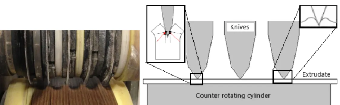
Slitting is used to split the extrudate up to five equal bands as a cutting system, since it is used in plastic thin sheets and does not cause any local melting when compared to other cutting systems, such as laser, hot knife cutting. Slitting station, which consists of flattener roller flattening the extrudate over the metal plate, cutting cylinder which have knives and positioner discs on it, and puller, can be seen Figure 3-5.
Figure 3-5: Slitting station and elements
After the extrudate is flattened by the roller, it is slit into four bands in equal width by being pressed it between knives and counter rotating cylinder and cutting continuously by rotating the knives. In the meantime, it is pulled by the puller continuously. Here, the cutting cylinder slits the polymer by generating compressive stresses between cutting cylinder and counter rotating cylinder which defines the cutting path. This process is called score slitting, where the angle of tip is important for cut quality and the lifetime of knife as seen in Fig.3-6 below.
Figure 3-6: Cutting cylinder elements and cutting forces at the knife tip
As told above, the angle of the knife tip important for cutting, when the angle decreases, cutting forces which the knife have to bear increases, consequently, life time of the knife decreases.On the other hand, when the angle increases, the knife tip starts to crush the product in slit edge causing bulge in edges as can be seen in Figure 3-6 at the right corner. This compression causes deformation in slit edges. When the knife is sharp, the slit edge will be smooth, but there will be dust. After using it, the knife becomes dull and rounded, in this case, there will be chips instead of dust in slit edge. Another concern is about counter rotating cylinder which is made of polyamide. As soon as, any defect or scratch happens in surface, this causes a gap, where the polymer could be squeezed and teared instead of being slit (N. N., 2013).
In addition to tip angle, the diameters of knives are also important for good slitting. When there is difference between two adjacent knives, the stripes can not be slit at the same time, but teared. This tearing may cause deformation or micro crack in slit edge in which residual stresses are formed. That is why same diameter is important to slit the band at the same time equally.
3.1.7 Winding station
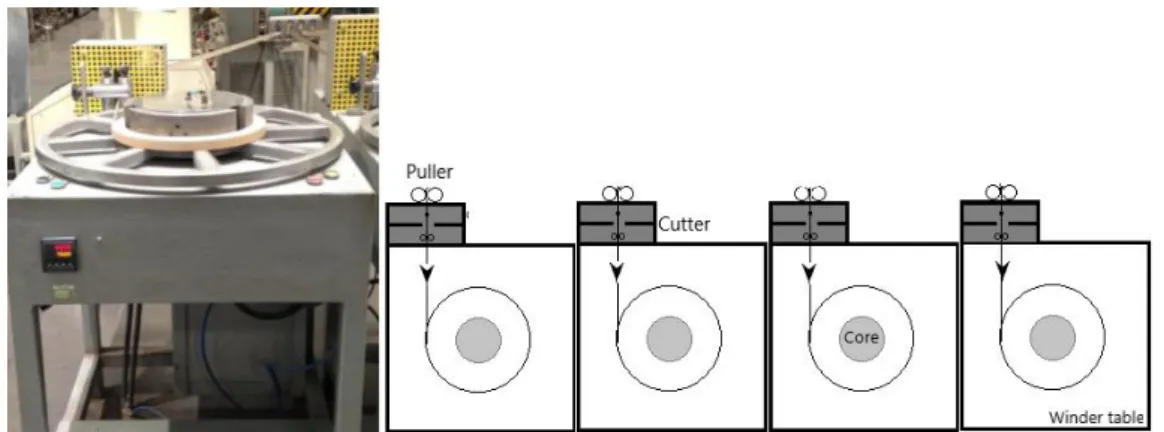
After slitting, separated extrudates are winded for packaging as a finished product in winding station. This process is carried out with up to five winders for winding slitted extrudates separately. Winding station consists of a vertical puller, a cutter, a core and a winder table which the winding process are carried out through the rotating wheel connected to electrical motor, and have buttons controlling the process on it, as seen in Figure 3-7.
Exrudates coming from slitting are pulled and adjusted by the puller changing flowing axis to winding axis. Adjusted extrudates are cut through the cutter when the order finished and end product has been obtained. Extrudates are winded around the core which defines the
inner diameter of rolls. So this winding process is basically combined of pulling and winding processes.
Figure 3-7: Example winder and configuration of winders in a line
Roll quality is used to satisfy the customer demands, defining the shape, size or consistency in thin products. Since the roll density, called as roll hardness, is a contributing cause of roll quality, it is used to define the differences between good and poor quality rolls. Roll density shows how much soft or hard the roll is. Soft rolls, which were winded too loose, cause problem during handling and storing due to failure of roundness. Each rotation of the roll for unwinding cause loose and tight tension which result in stresses. Hard rolls, which were winded too tight, bring also some problems. They cause blocking by sticking to each other of very thin layers due to high tension. Hard rolls show also bagginess and wrinkling problem. The web may have thicker and thinner areas as it is not highly precise. When these thicker points overlap during winding continuously, it is deformed creating ridge, which is known as bagginess. Hard rolls have more residual stresses due to high tension (Smith, 2007). The tension is changing during winding depending on roll diameter. As seen in Figure 3-8, when the roll diameter increases, the tension at outside decreases.
There are three principles for controlling the roll hardness; tension, nip and torque principles, shortly called TNT by Smith. In tension principle, when the product is pulled with more tension, more harder winded rolls are produced as shown in Figure 3-9. For this reason, roll hardness can be improved in elastic films by controlling the tension which could be calculated empirical or from modulus of elasticity (Smith,2007).
Figure 3-9: Scheme of tension principle for roll hardness [Smith,2007]
For inelastic films, nip principle is used to control the roll hardness by applying nip load to remove the air between layers, as seen in Figure 3-10.
Figure 3-10: Scheme of nip principle for roll hardness [Smith,2007]
In torque principle, the tension is generated in the center of roll and transferred through the layers and tightens the inner layers. The basic idea underlying here is same with the tension principle (Smith, 2007).
4
Introduction to Design of Experiments
Experiment is a scientific test where the input parameters are changed depending on a given rule to study the reasons for this change in the result. They are used in almost all areas to investigate the performance of systems and processes. These processes can be combination of methods, machines and people that convert any input to an observable result which was defined as banana in this project. While some of these input parameters are controllable, some can be uncontrollable. The aim of the experiment is to know most effective parameters on the result and how to use them to minimize the uncontrollable parameters (Cavazutti, 2013).
Some developed techniques enable the experiments to be performed in an efficient way. These techniques used for improving experiments are called design of experiments (DOE) or experimental design. This technique includes some statistical methods to avoid experimental noises, which deviate the results, by analyzing the results. These basic methods are replication, randomization and blocking. Replication is used to obtain more precise datas by repeating the tests. Randomization enables the tests to be performed randomly, so that the result can be achieved independently from the conditions used before. Blocking is used to avoid bias effect by organizing the experiments in groups which are similar to one another. So that, the precision could be achieved (Cavazutti, 2013).
Now, the terminology used in DOE will be shortly explained. As mentioned before, the problem to be studied must be defined, then, chosen the parameters as input variables. Each parameter must have defined range of variability which is known design space. This range is limited in DOE, so that qualitative and quantitative variables can be coped with. Levels, that show the number of different values a parameter, and DOE method are chosen depending on appropriate number of experiments. In DOE, desired result and the experiments to be conducted are known as response variable and sample space respectively.
Most common DOE techniques used in practice are randomized complete block design, full factorial, fractional factorial, latin hypercube sampling and central composite design. In this project, full factorial experimental design has been used.
Full factorial is the most used experimental design. The experiment number is calculated by multiplying levels of parameters. In case of one
three-levels and two two-levels parameters, the number of experiments to be performed is 12 (3x2x2), as seen in Table 4-1.
Parameters
Test No Blade Spacer disc Flattener
1 New Plastic with
2 New Plastic without
3 New Metal with
4 New Metal without
5 Used Plastic with
6 Used Plastic without
7 Used Metal with
8 Used Metal without
9 Grinded Plastic with
10 Grinded Plastic without
11 Grinded Metal with
12 Grinded Metal without
Table 4-1: Example full factorial test design
After choosing the parameters which could have influence on banana, tests have been performed according to full factorial design. After collecting the results, these results have been statistically analyzed by using two features of Minitab software which is most common for statistical DOE. One of these used features is the main effects plot which shows the main influences of parameters on banana and how these affect the banana. Other feature is the interaction plot where the relations between parameters, and influences of them on banana can be seen. These features can be seen in the chapter of Experimental works.
![Figure 2-1: Styrene (monomer) and polystyrene (polymer) [Ebewele, 2000]](https://thumb-eu.123doks.com/thumbv2/9libnet/5468307.105728/18.892.175.692.725.910/figure-styrene-monomer-polystyrene-polymer-ebewele.webp)
![Table 2-1: ABS general properties [Savasci et al., 2008]](https://thumb-eu.123doks.com/thumbv2/9libnet/5468307.105728/23.892.164.748.123.678/table-abs-general-properties-savasci-al.webp)
![Figure 2-7: Specific volume-Temperature plot; (A)Liquid zone; (B)viscous liquid with some elastic response; (C)rubbery zone; (D)glassy zone; (E)crystallites in a rubbery matrix; (F)crystallites in a glassy matrix [Ebewele, 2000]](https://thumb-eu.123doks.com/thumbv2/9libnet/5468307.105728/25.892.159.705.125.489/figure-specific-temperature-response-rubbery-crystallites-crystallites-ebewele.webp)
![Figure 2-8: State plot of amorphous polymers depending on temperature [Stommel, 2016]](https://thumb-eu.123doks.com/thumbv2/9libnet/5468307.105728/26.892.197.677.127.430/figure-state-plot-amorphous-polymers-depending-temperature-stommel.webp)
![Figure 2-11: Stress relaxation [Cerrada, 2005]](https://thumb-eu.123doks.com/thumbv2/9libnet/5468307.105728/30.892.202.668.125.540/figure-stress-relaxation-cerrada.webp)
![Figure 2-15: Molecular orientation by cross-sectional view of the die [Frankland, 2016]](https://thumb-eu.123doks.com/thumbv2/9libnet/5468307.105728/34.892.160.697.406.645/figure-molecular-orientation-cross-sectional-view-die-frankland.webp)
![Figure 2-17: Residual stresses in a finished part [N.N., 2006]](https://thumb-eu.123doks.com/thumbv2/9libnet/5468307.105728/37.892.169.714.330.865/figure-residual-stresses-finished-n-n.webp)