Beaming of electromagnetic waves emitted
through a subwavelength annular aperture
Humeyra Caglayan, Irfan Bulu, and Ekmel Ozbay
Department of Physics and the Nanotechnology Research Center, Bilkent University, 06800 Ankara, Turkey
Received July 5, 2005; accepted August 21, 2005; posted September 1, 2005 (Doc. ID 63177) We study the diffraction of electromagnetic waves from subwavelength metallic circular apertures in the mi-crowave spectrum. The theoretical and experimental demonstration of the near- and far-field electromagnetic distributions for subwavelength circular annular apertures and circular annular apertures surrounded by con-centric periodic grooves are reported here. The metallic samples had a subwavelength hole with a diameter of 8 mm and had concentric grooves with a periodicity of 16 mm. We present the angular transmission distribu-tions from circular annular apertures, and circular annular apertures surrounded by concentric periodic grooves. At the surface-mode resonance frequency the transmitted electromagnetic waves from the subwave-length circular annular aperture surrounded by concentric periodic grooves have a strong angular confinement with an angular divergence of ±3°. This represents a fourfold reduction when compared with the angular di-vergence of the beam transmitted from the subwavelength circular aperture. © 2006 Optical Society of America
OCIS codes: 240.6680, 230.1950.
1. INTRODUCTION
The transmission of electromagnetic (EM) waves through a single subwavelength aperture has been studied for many years. As defined in the standard diffraction theory by Bethe1 in 1944, a circular aperture with a subwave-length diameter transmits EM waves very poorly ⬃共d/兲4, and exiting EM waves are fully diffracted in all directions. This aperture had two disadvantages: low transmission as well as diffraction, the main problems of manipulating light, especially for subwavelength scales. However, it has been shown that not only the enhance-ment of the transmission but also the confineenhance-ment of the transmitted beam is possible by means of surrounding the metal surface of the subwavelength apertures with peri-odic corrugations.2These effects are attributed to the cou-pling of incident light to surface plasmons (SPs). This idea has stimulated studies on this subject, and numerous ex-perimental and theoretical work has been performed in the optical and microwave regimes.3–11
SPs are the collective excitation of electrons at the sur-face of a conductor in the longitudinal direction. As SP modes have longer wave vectors than light waves of the same energy, EM radiation does not interact with the SP modes of a smooth metal surface.12When the metal sur-face surrounding the subwavelength hole is corrugated, the incident light can couple to SPs. A resonant interac-tion leads to an enhanced transmission at wavelengths determined by the corrugation period.13,14
In 1992 optical near-field microscope researchers pro-posed the use of coaxial aperture to achieve enhanced transmission.15 Baida et al.16 proposed a similar idea, stating that it was possible to optimize the transmission enhancement and angular confinement using a subwave-length circular coaxial aperture with a surrounding array of grooves. Recently, we have reported enhanced trans-mission in microwave regime using structures with
sub-wavelength circular coaxial apertures. This enhanced transmission is assisted by the guided mode of the coaxial waveguide and coupling to the surface plasmons.17In this paper, we report the near-field and far-field distributions of EM waves emitted from subwavelength circular annu-lar apertures and circuannu-lar annuannu-lar apertures surrounded by concentric periodic grooves.
2. EXPERIMENT AND ANALYSIS
The schematic description of our structures is shown in Fig. 1. All four metallic (aluminum) structures have a subwavelength hole in the center with a diameter (a) of 8 mm. The gratingless sample (Sample 1) with a thickness 共t兲 of 8 mm was used as a reference sample. The second sample has an identical aperture surrounded by six rect-angular grooves. The periodicity of the grooves is 16 mm, and the thickness共w兲 of the grooved metal is 3.2 mm. The measurements were performed in the microwave spec-trum of 10–18 GHz, corresponding to a wavelength region of 16.7–30.0 mm. Figure 2 illustrates the experimental setup for the transmission and angular-distribution mea-surements. The experimental setup consists of an Hewlett Pockard 8510C network analyzer and two standard-gain horn antennas to measure the transmis-sion amplitude. Radiation is normally incident upon the sample from 15 cm by the source antenna. The receiver antenna is 10 cm away from the sample for the transmis-sion measurements.
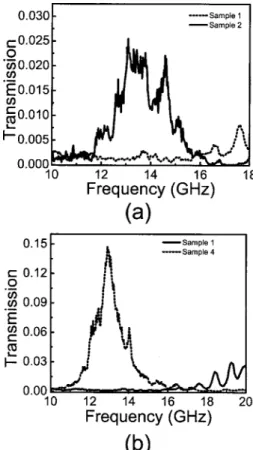
For Sample 2, a transmission peak was measured around 13 GHz with a transmission amplitude of 0.025 [Fig. 3(a)]. A twentyfold enhancement was achieved around the SP resonance frequency with Sample 2. For a further increase in transmission, we designed an annular aperture that can support a TE mode around 13 GHz. This structure (Sample 3) is identical to Sample 1, with a
Caglayan et al. Vol. 23, No. 3 / March 2006 / J. Opt. Soc. Am. B 419
rod inside the hole. The diameter of the rod is 6.6 mm, and the length of the rod is 8 mm. The combination of the annular aperture and grooved structure (Sample 4) showed extraordinary high transmission at 12.9 GHz (23.25 mm) via the coupling to the surface waves and the guided mode of annular aperture [Fig. 3(b)]. Including the reduction in the area of the aperture, a 450-fold enhance-ment was achieved through the subwavelength annular aperture.17
Enhancement of the transmission and beaming are re-ferred to the SP waves on the surface. To observe these surface waves, we scanned the output surface of Sample 2. Owing to the restriction of the experimental setup, we were able to scan 4 mm away from the surface. Figure 4(a) shows the calculated field on the output surface of Sample 2, where the dotted curves refer to the aperture surface. The measured and calculated field was 4 mm away from the output surface of Sample 2 and is shown in Fig. 4(b). The FWHM of the measured field is equal to 9共⯝/2.5兲 mm. The subwavelength FWHM suggests the existence of the evanescent field at this distance.
In the experimental setup for angular-distribution measurements, the receiver antenna was placed 50 cm away from the sample’s back face and was connected to a
Fig. 1. Schematics of the four metallic samples and a top view of Sample 2.
Fig. 2. Experiment setup for transmission and angular distri-bution measurements.
Fig. 3. Measured transmission results for (a) Samples 1 and 2 and (b) Samples 1 and 4.
Fig. 4. (a) Calculated field on the output surface of Sample 2. (b) Measured and calculated field 4 mm away from the surface of Sample 2.
rotating arm to measure the angular dependence of the far-field radiation. Theoretical calculations were per-formed using simulations based on the finite-difference time-domain (FDTD) method based simulations.
Figure 5 shows the normalized measured and calcu-lated angular transmission distribution at the resonance frequency for Samples 1 and 2. Angular divergence of the transmitted beam from Sample 1 is ±12°, whereas the transmitted beam that emerges from Sample 2 is ±3°. The angular divergence of the beam reduced 4 times com-pared with the transmitted beam from Sample 1.
The angular transmission intensity distribution at the enhanced transmission frequency for Samples 3 and 4 is presented in Fig. 6. FWHM divergence of the beam is ±12° and ±3°, respectively. The angular divergence of the beam transmitted from Sample 3 is very similar to the beam transmitted through Sample 1.
The light emerging from the groove structure is emit-ted through a subwavelength aperture. It is expecemit-ted that the emitted EM waves would quickly diffract in all
direc-tions owing to the subwavelength dimensions of the aperture.1On the contrary, we observed that the emitted EM waves are confined to a narrow spatial region when the subwavelength aperture was surrounded by periodic circular grooves. The surface-wave momentum and the momentum of the corrugation around the subwavelength aperture limit the allowed range of momentum of the reradiated EM waves. The circular symmetry of the struc-ture suggests that the off-axis beams are suppressed ow-ing to the destructive interference. In addition, the beams normal to the surface of the aperture constructively inter-fere, since the beams emitted from the hole and grooves are in phase.
The comparison of the calculated far-field distributions of EM waves emitted from Samples 1 and 4 is presented in Fig. 7. Calculated FWHM divergence of the beam transmitted from Samples 1 and 4 is ±12° and ±3°, re-spectively, in agreement with measurements. Sample 4 can optimize the angular divergence of the beam, since FWHM of the beam is reduced fourfold compared with the beam transmitted through a subwavelength aperture (Sample 1).
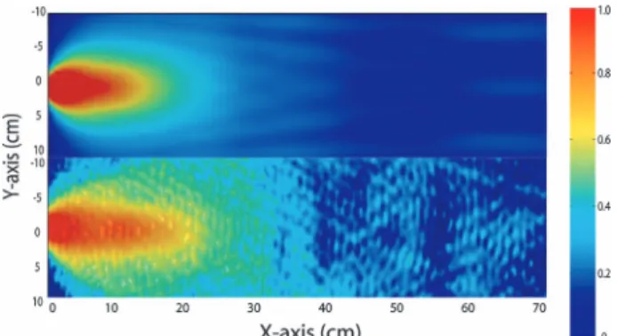
Figure 8 shows the calculated (top) and measured (bot-tom) electric-field distribution of the transmitted beam from Sample 4 at the resonance frequency. The measured electric-field intensity at 13 GHz over a region of a 44 cm⫻70 cm area on the output side of the aperture is measured with a monopole antenna with a resolution of 0.5 cm. Our experiment shows that the electric-field
in-Fig. 5. Normalized angular transmission distributions for (a) Sample 1 and (b) Sample 2 at resonance frequency (13 GHz).
Fig. 6. Normalized angular transmission distributions for (a) Sample 3 and (b) Sample 4 at resonance frequency (13 GHz).
Fig. 7. Comparison of the calculated far-field results for Samples 1 and 4.
Fig. 8. Calculated (top) and measured (bottom) electric-field dis-tribution from Sample 4 at the resonance frequency.
tensity is confined to a narrow spatial region and propa-gates without diffracting into a wide angular region. The theoretical result is in good agreement with the experi-mental result.
3. CONCLUSION
In conclusion, we presented measured and calculated near-field and far-field EM distributions for subwave-length circular annular apertures with and without con-centric periodic grooves in the microwave regime. We showed that the beam transmitted from circular aper-tures surrounded by concentric periodic grooves has a subwavelength FWHM near the aperture. Furthermore, we measured the normalized angular transmission distri-butions from these apertures. The beam transmitted from the circular annular apertures surrounded by concentric grooves (Sample 4) is 450 times more enhanced, and the angular divergence of the beam is fourfold reduced com-pared with the beam transmitted through a subwave-length aperture (Sample 1). These effects can be ex-plained by coupling of EM waves to the SPs and the guided mode of annular aperture. The experimental re-sults are in good agreement with FDTD-based theoretical calculations.
ACKNOWLEDGMENTS
This work was supported by projects EU-DALHM, EU NOE-METAMORPHOSE, EU NOE-PHOREMOST, and TUBITAK-104E090. One of the authors (E.O.) acknowl-edges partial support from the Turkish Academy of Sci-ences.
H. Caglayan is the corresponding author and can be reached via e-mail at [email protected].
REFERENCES
1. H. A. Bethe, “Theory of diffraction by small holes,” Phys. Rev. 66, 163182 (1944).
2. H. J. Lezec, A. Degiron, E. Devaux, R. A. Linke, L. Martin-Moreno, F. J. Garcia-Vidal, and T. W. Ebbesen, “Beaming light from a subwavelength aperture,” Science 297, 820–822 (2002).
3. F. J. Garcia-Vidal, H. J. Lezec, T. W. Ebbesen, and L. Martin-Moreno, “Multiple paths to enhance optical
transmission through a single subwavelength slit,” Phys. Rev. Lett. 90, 213901 (2003).
4. S. S. Akarca-Biyikli, I. Bulu, and E. Ozbay, “Enhanced transmission of microwave radiation in one-dimensional metallic gratings with subwavelength aperture,” Appl. Phys. Lett. 85, 1098–1100 (2004).
5. L. Martin-Moreno, F. J. Garcia-Vidal, H. J. Lezec, A. Degiron, and T. W. Ebbesen, “Theory of highly directional emission from a single subwavelength aperture surrounded by surface corrugations,” Phys. Rev. Lett. 90, 167401 (2003).
6. M. J. Lockyear, A. P. Hibbins, J. R. Sambles, and C. R. Lawrence, “Surface-topography-induced enhanced transmission and directivity of microwave radiation through a subwavelength circular metal aperture,” Appl. Phys. Lett. 84, 2040–2042 (2004).
7. J. M. Steele, C. E. Moran, A. Lee, C. M. Aguirre, and N. J. Halas, “Metallodielectric gratings with subwavelength slots: optical properties,” Phys. Rev. B 68, 205103 (2003). 8. N. Bonod, S. Enoch, L. Li, P. Evgeny, and M. Neviere,
“Resonant optical transmission through thin metallic films with and without holes,” Opt. Express 11, 482–490 (2003). 9. A. G. Borisov, F. J. Garca de Abajo, and S. V. Shabanov, “Role of electromagnetic trapped modes in extraordinary transmission in nanostructured materials,” Phys. Rev. B
71, 075408 (2005).
10. S. S. Akarca-Biyikli, I. Bulu, and E. Ozbay, “Resonant excitation of surface plasmons in one-dimensional metallic grating structures at microwave frequencies,” J. Opt. A Pure Appl. Opt. 7, 159–164 (2005).
11. M. J. Lockyear, A. P. Hibbins, J R. Sambles, and C. R. Lawrence, “Enhanced microwave transmission through a single subwavelength aperture surrounded by concentric grooves,” J. Opt. A Pure Appl. Opt. 7, 152–158 (2005). 12. H. Raether, Surface Plasmons on Smooth and Rough
Surfaces and on Gratings (Springer-Verlag, 1988).
13. Y. Teng, E. A. Stern, “Plasma radiation from metal grating surfaces,” Phys. Rev. Lett. 19, 511–514 (1967).
14. T. Thio, H. J. Lezec, T. W. Ebessen, K. M. Pellerin, G. D. Lewen, A. Nahata, and R. A. Linke, “Giant optical transmission of sub-wavelength apertures: physics and applications,” Nanotechnology 13, 429–432 (2002). 15. U. C. Fischer and M. Zapletal, “The concept of a coaxial tip
as a probe for scanning near field optical microscopy and steps towards a realisation,” Ultramicroscopy 42–44, 393–398 (1992).
16. F. I. Baida, D. Van Labeke, and B. Guzial, “Enhanced confined light transmission by single subwavelength apertures in metallic films,” Appl. Opt. 42, 6811–6815 (2003).
17. H. Caglayan, I. Bulu, and E. Ozbay, “Extraordinary grating-coupled microwave transmission through a subwavelength annular aperture,” Opt. Express 13,
1666–1671 (2005).