Abstract—In this paper, we present how a capacitive micromachined ultrasonic transducer (cMUT) couples to the immersion medium, based on an accurate parametric model. We show that the velocity of cMUT membrane can be written as a sum of an average velocity term and a residual term. We demonstrate that this residual term carries non-zero energy at the parallel resonance frequency by investigating the interaction between the cMUT cell and a liquid medium. We develop a model that is also applicable around the parallel resonance frequency.
I. INTRODUCTION
n recent years, capacitive micromachined ultrasonic transducers (cMUT) found many application areas. Most of these involve the immersion of the transducer into a liquid medium [1]. The modelling of cMUT in immersion is still a concern in order to have a full characterization and to design a transducer.
In vacuum, the mechanical impedance of cMUT shows successive series and parallel resonance frequencies, which can be modelled with the lumped elements, L and C [2]. On the other hand, when immersed in water, all these frequencies shift to smaller values. It is important to fully characterize this effect, since the first parallel resonance frequency determines the maximum bandwidth that can be obtainable with cMUT. In this work, we investigate the behaviour of the circular cMUT membrane around its parallel resonance frequency when loaded with a liquid medium. Using the results, we rearrange the lumped element model of cMUT membrane given in [2] to couple the membrane to the medium and obtain a model of cMUT membrane, which is also valid around the parallel resonance frequency.
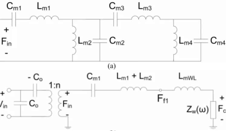
In a recent work [2], we presented an accurate parametric model of a circular cMUT membrane in vacuum, as shown in Fig. 1 (a). This model represents the mechanical impedance of the membrane up to the third parallel resonance frequency. The model takes into account for all membrane dimensions and bias conditions. This model is a parametric normalized model, which makes the L and C values independent of the conditions mentioned above. It is also possible to use this
model to couple cMUT to the medium with proper arrangement. Fig. 1 (b) shows the model in Fig. 1 (a) rearranged for immersion. The electrical side is also included. In this equivalent circuit; C0 is the shunt input capacitance, -C0
is the spring softening capacitance and n is the turns ratio of the electromechanical transformer. The radiation impedance of cMUT is identified as the sum of the radiation impedance of an equal sized piston,
2
( ) ( ( ) ( ))
W w w
Z ω π ρ= a c R ka + jX ka (1) and an extra inductive loading, whose value is equal to,
3
0.27ρ (4 / 3)π =
mWL W
L a (2) where a is the radius of the membrane, ρw is the density of the
water and cw is the speed of sound in the water. This
equivalent circuit is shown to work well around the series resonance frequency in [3] with the experimental data given in [4]. However, as shown in [5], the equivalent circuit in Fig. 1 (b) is valid up to the 2.4 times the series resonance frequency, fs. In order to accommodate the parallel resonance frequency,
fp, we need a further arrangement.
(a)
(b)
Fig. 1. (a) Lumped element model of cMUT membrane in vacuum (b) Equivalent circuit of cMUT membrane immersed in water around the series resonance frequency.
II. INTERACTIONWITH A LIQUIDMEDIUM We create a finite element model (FEM) of a circular silicon nitride cMUT membrane in water [6] using a commercially
Interaction Between a cMUT cell and a Liquid
Medium around the Parallel Resonance
Frequency
Muhammed N. Senlik, Abdullah Atalar, and Selim Olcum
Electrical and Electronics Engineering Department, Bilkent University, Ankara, TURKEY
I
available program, ANSYSTM. The advantage of FEM is that
it is possible to change the material and the medium properties at will.
We simulated a silicon nitride membrane having a radius, a equals 20 µm and a thickness, lt 1 µm. The specific acoustic
impedance of the immersion medium is given by Z0=ρwcw. We
created a fictitious liquid medium by changing either ρw or cw
in order to increase Z0. Fig. 2 shows the total impedance
calculated at the mechanical side of the electromechanical transformer of the Mason’s equivalent circuit [7]. In vacuum, the series, fs and the parallel, fp resonance frequencies of the
membrane are 12 MHz and 42 MHz, respectively. On the other hand, when immersed in water, those frequencies shift to 5 MHz and 25 MHz. When we increased the speed of the sound to 1000 times that of cw, we see that the resonance
frequencies do not change compared to those in water, showing that speed of sound in the medium does not change the acoustic loading on the membrane. We also increased the density of the medium making 10 times of ρw, we see that the
resonance frequencies decrease. It is clear that the density of the medium strongly affects the loading on the medium, which
is an expected result from (2).
Fig. 2. The total impedance of cMUT membrane seen at the mechanical side of the electromechanical transformer of the Mason’s equivalent circuit for different acoustic media.
The mechanical impedance is defined as the ratio of the total force applied to the membrane divided by the average velocity of the membrane [8]. This is equivalent to writing the velocity of the membrane as a sum of an average velocity and a residual term [2], which is the difference between the actual velocity and the average velocity,
( ) ( )
' = − average
v r v r v (3) and its average is equal to zero. Although this term does not contribute to the total radiated energy, it still creates an extra reactance by wobbling the water over the membrane surface locally. In order to calculate the energy that the residual velocity term carries, we calculate the following
2 residual 2 1 v ' v ' (r)r dr d a θ π =
∫∫
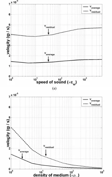
(4) We find the value of (4) at the parallel resonance frequency for increasing acoustic impedances by changing ρ or c with respect to its corresponding values in water. Fig. 3 (a) shows that as the speed of sound increases, while the values of vaverage andvresidual do not change. On the other hand, Fig. 3 (b) indicates
that both of these velocities decrease as the density of the medium increases.
(a)
(b)
Fig. 3. Change of vaverage and vresidual at the parallel resonance frequency for
increasing (a) speed of sound in the medium (b) density of the medium. We note that even at the parallel resonance frequency, vresidual does not become zero as shown in Fig. 3. This result
shows that the membrane is loaded with the liquid medium in a fundamentally different way compared to the solids. In a solid, the boundary between the medium and the membrane is a rigid boundary not allowing the membrane to move. On the other hand, if the boundary is liquid, it allows the boundary to move even it is an infinite acoustic impedance media. We have to consider this result for the rearrangement of the model
2007 IEEE Ultrasonics Symposium 2152
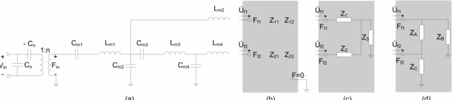
Fig. 4 (a) Lumped element model of mechanical dynamics of cMUT membrane, back-surface terminated with F=0 (b) Impedance matrix for coupling to water (c) Circuit network for coupling to water (d) Circuit network for coupling to water after Y-∆ transformation.
in Fig. 1 (a) to the one that is appropriate to couple to the medium. III. MODEL OF CMUTMEMBRANE IN WATER
In order to rearrange the model, we must consider the physical properties of cMUT membrane. cMUT membrane has two opposite surfaces facing each other, which implies that cMUT must have two sets of symmetric acoustic ports to couple to the medium [2]. If one of the medium is vacuum at the cMUT’s back surface, the corresponding ports will be terminated with force equals zero, F=0. We rearrange the model in Fig. 1 (a) to the one depicted in Fig. 4 (a). In this model, C1, L1 and L2 represent the piston motion of the
membrane, which is the direct implication of the impedance definition [8]. The higher of the modes are energized by the piston path via 1:1 transformer, for clearance the transformer is not shown in Fig. 4 (a). The membrane reaches the medium with the acoustic ports denoted by Ff1 and Ff2. The front and
the back surfaces of the membrane is connected by C2 and C4,
which is the direct implication of the results obtained from the interaction between the membrane and the liquid medium. The membrane is connected to the ports with L2 and L4.
The membrane couples to the water with the impedance matrix in Fig. 4 (b). In order to calculate the elements, Zij of
this matrix, we replace Fin with –Zin, which is the negative of
the total impedance seen at the mechanical side of the transformer. The off-diagonal elements of the impedance matrix show strong symmetry up to fp. This symmetry allows
us to represent the impedance matrix with the network in Fig. 4 (c).
The power is coupled to the medium with the real part of the radiation impedance of cMUT. This coupling occurs over the piston path; hence the radiation resistance of cMUT must be at the end of this path. We perform a Y-∆ transformation between the jωL2 + Z1, real part of Z2 and Z3 such that only the
impedance between the piston path and node, F=0 has a real part, and obtain ZA, ZB and ZC.
The impedances except the ones on the piston path and ZB
model the parallel resonance frequency of the membrane. In [5], it is shown that the radiation impedance of the circular cMUT membrane can be approximated as the radiation impedance given by Greenspan in [9] for a clamp radiator. This impedance can be used in place of ZB.
IV. CONCLUSION
In this work, we investigated the interaction between a circular cMUT cell and a liquid medium around the membrane’s parallel resonance frequency. We showed that the loading on the membrane is not affected by the speed of the sound in the medium; however it is a strong function of the density of the medium. We write the velocity of the membrane as a sum of the membrane’s average velocity and a residual term, which is the difference between the actual membrane velocity and the average velocity. We found that at the parallel resonance frequency, both of these velocities remain the same, as the specific acoustic impedance of the medium is increased by changing the speed of the sound in the medium. On the other hand, these velocities decrease for increasing density of the medium. The residual component of the membrane velocity does not become zero at the parallel resonance frequency, showing that it carries non-zero energy. Based on this result, we rearrange the lumped element model of cMUT membrane given in [2] to couple to the surrounding medium. During the rearrangement, the physical properties of the membrane are also taken into account. The capacitors are used to connect the front and back surfaces of the membrane, whereas inductors are used to couple to the medium. We identify the network through which the membrane couples to the medium. We identify the radiation impedance of cMUT membrane, which can be approximated as the radiation impedance calculated for a clamp radiator given by Greenspan [5], [9].
V. ACKNOWLEDGEMENTS
This work is supported in part by Turkish Scientific and Research Council (TUBITAK) under project grant 105E023.
REFERENCES
[1] O. Oralkan, A. S. Ergun, C-H. Cheng, J. A. Johnson, M. Karaman, T. H. Lee, and B. T. Khuri-Yakub, “Volumetric ultrasound imaging using 2-D CMUT arrays,” IEEE Trans. Ultrason., Ferroelect., Freq. Contr., vol. 50, pp. 1581-1594, 2003.
[2] H. Köymen, M. N. Senlik, A. Atalar, and S. Olcum, “Parametric linear modeling of circular cMUT membranes in vacuum,” IEEE Trans.
Ultrason., Ferroelect., Freq. Contr., vol. 54, pp. 1229-1239, 2007.
[3] M. N. Senlik, A. Atalar, H. Köymen, and S. Olcum, “Radiation impedance and equivalent circuit for immersed cMUT array element,” in
Proc. IEEE Ultrason. Symp., 2006, pp. 1951-1954.
2007 IEEE Ultrasonics Symposium 2153
[4] J. Knight, J. McLean, and F. L. Degertekin, “Low Temperature Fabrication Of Immersion Capacitive Micromachined Ultrasonic Transducers On Silicon And Dielectric Substrates,” IEEE Trans.
Ultrason., Ferroelect., Freq. Contr., vol. 51, pp. 1324-1333, 2004.
[5] M. N. Senlik, S. Olcum, A. Atalar, and H. Köymen, “Radiation impedance of a circular cMUT cell below the series resonance,” IEEE
Trans. Ultrason., Ferroelect., Freq. Contr., submitted for publication.
[6] B. Bayram, E. Hæggström, A. S. Ergun, G. G. Yaralioglu and B. T. Khuri-Yakub, “Dynamic analysis of cMUTs in different regimes of operation,” in Proc. IEEE Ultrason. Symp., 2003, pp. 481-484.
[7] I. Ladabaum, X. Jin, H. T. Soh, A. Atalar, and B. T. Khuri-Yakub, “Surface micromachined capacitive ultrasonic transducers,” IEEE Trans.
Ultrason., Ferroelect., Freq. Contr., vol. 45, pp. 678-690, 1998.
[8] W. Mason, “Electromechanical transducers and wave filters,” 2nd Ed., Van. Nostrand, New York, 1948.
[9] M. Greenspan, “Piston radiator: some extensions of the theory,” J.
Acoust. Soc. Am., vol. 65, pp. 608-621, 1979.
2007 IEEE Ultrasonics Symposium 2154