SN Applied Sciences (2019) 1:1712 | https://doi.org/10.1007/s42452-019-1786-4
An ensemble learning estimation of the effect of magnetic coupling
on switching frequency value in wireless power transfer system
for electric vehicles
Kadir Sabanci1 · Selami Balci1 · Muhammet Fatih Aslan1
Received: 18 August 2019 / Accepted: 25 November 2019 / Published online: 28 November 2019 © Springer Nature Switzerland AG 2019
Abstract
Wireless power transmission (WPT) systems of small power levels used in the medical and communications sectors have been developed in recent years for tens of kW power levels for charging stations of electric vehicles. In wireless charg-ing systems, power transfer is provided by magnetic couplcharg-ing uscharg-ing coreless transformers, and in these systems, power electronics circuit design is the crucial point. The inductor behavior as a series resonance circuit element required in the power electronics circuit of WPT systems varies according to the magnetic coupling positioning errors between the primary and secondary sides of the coreless transformer. Therefore, the considering that the resonant capacitor value is constant in the resonance tank circuit, the switching frequency value in the power electronics circuit must be adaptively controlled so that the transferred power value can be carried out efficiently. In this study, the parametric simulations have been performed using Ansys-Electronics software to adaptively control the switching frequency value in the inverter circuit depending on the magnetic coupling coefficients in the WPT circuit designed at a power value of 25 kW. Based on the data obtained from these simulation studies according to different scenarios, the switching frequency value can be changed adaptively and thus the WPT efficiency can be kept at a certain level by providing resonance in each condition. Also, 105 efficiency data were obtained by using Ansys-Electronics parametric solver for many variables such as coreless transformer, resonant circuit parameters of power electronic circuit, switching frequency and magnetic coupling. The WPT efficiency is predicted by ensemble decision trees algorithm. The results show that the estimation with ensemble decision trees is quite successful.
Keywords Wireless charging systems · Electric vehicle · Coreless transformer · Magnetic coupling · Resonant converter ·
Ensemble decision trees
1 Introduction
Environmental damage of fossil fuel vehicles and the possibility of depletion of fossil fuels in the future have accelerated the development of electric vehicles (EVs) in recent years [1]. Because of the increasing number of electric vehicles, charging stations can be designed as wired and/or wireless systems for charging. Efforts to improve the efficiency of wireless charging systems
are still ongoing, but they also have advantages due to mechanical and safety problems in wired systems [2]. The use of coreless transformers is common in WPT charging systems and the determination of electromag-netic behavior is an important issue in power electron-ics circuit design. However, in conventional core trans-formers, it has been shown that the use of low frequency magnetic waves is effective for WPT from reinforced concrete walls when a magnetic wave under 400 Hz is * Selami Balci, [email protected]; Kadir Sabanci, [email protected]; Muhammet Fatih Aslan, [email protected] |
used [3]. On the other hand, in coreless WPT systems, the switching elements of the inverters generally operate at medium and high frequency values. Designs with high frequency soft magnetic materials (such as Ferrite core) are also available in the literature.
The resonance frequency changes continuously depending on the length of the air gap between the pri-mary (transmitter) and the secondary (receiver) coils, and the positioning errors. The maximum efficiency does not change up to a certain distance. Large air gaps result in loosely magnetic coupling. With a tightly magnetic cou-pling in the resonance, electrical energy can be transferred in high efficiency. In a study conducted in this context, the applicability of WPT with high efficiency was proposed by using small size antennas that can be placed under the EVs [4]. The design of the series resonant coils and the switch-ing frequency selection are the main design factors for the high efficiency of WPT system, for the high power trans-mission efficiency and reduction of the electromagnetic fields emitted around the system [5–7].
In [8], the basic principles of WPT using magnetic field resonance are introduced and techniques for the design of a series of resonance magnetic coils, the formation of magnetic field distribution, and electromagnetic field (EMF) noise reduction methods are described. Various electric vehicle charging methods without cable exten-sions are under development, or are now used as aftermar-ket options in the automotive maraftermar-ket. WPT is an accepted term for wireless charging. It is also used synonymously with Inductive Power Transmission (IPT) and Magnetic Resonance Coupling (MRC). WPT technology is on the onset; it lacks methods for standardization, in particular interoperability, switching frequency selection, magnetic fringe field suppression, and power flow regulation. A new analysis concept is proposed which is the similar to the power transmission grid with primary frequency selection and reactive power voltage control with the set secondary side for the power flow in WPT [9].
In the literature for WPT systems, studies have gen-erally been carried out on systems with a single-phase transformer. On the other hand, [10] proposes a system capable of dynamically transmitting three-phase power system and tested on an electric train prototype [11, 12].
In this study, parametric simulation has been proposed to prevent breaks from resonance due to magnetic cou-pling coefficient and to realize adaptive frequency and duty cycle control. After the simulation studies, in order to provide adaptive frequency control, various switching fre-quency and duty cycle values according to the magnetic coupling coefficients were determined. Thus, the switch-ing frequency values were reported graphically accordswitch-ing to the coupling coefficients in order to achieve optimum efficiency, and 105 efficiency data were obtained by using parametric solver for many variables such as coreless trans-former, resonant circuit parameters of power electronic circuit, switching frequency and magnetic coupling.
2 Coreless transformer equivalent circuit
and coupling effect
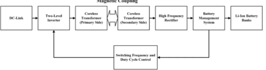
The proposed block diagram of the three-phase WPT system is shown in Fig. 1. This system consists of a star/ star-connected three-phase coreless transformer and a three-phase two-level voltage source inverter circuit. The power supply of the charging station is the AC–DC con-verter circuit that rectifies the three-phase grid with the power-factor-correction (PFC) rectifier circuit.
The switching of the inverter circuit is performed at the switching frequency value determined by the leak-age inductance value of the coreless transformer and the series resonant capacitor with fixed value. However, the magnetic coupling between the primary and the second-ary sides may vsecond-ary in positioning errors and in this condi-tion the resonance is disturbed. In this context, the switch-ing frequency must be changed in order to restore the resonance.
The primary and secondary sides of the three-phase coreless transformer, which is recommended for WPT, are connected as star/star in Fig. 2. Since the equivalent induct-ance value from the primary side of this transformer is an important variable for the resonance circuit, equations can be written for the coupling coefficient. The coupling effect between the primary and secondary depends on the dis-tance between each other, and for loosely/tightly coupling. If the coupling coefficient is less than 0.5, it can be said as
Fig. 1 Block diagram of the
three-phase WPT charging system
loosely coupling, and if it is above 0.5, it can be said as tightly coupling. Furthermore, the magnetic coupling is made worse if the electric vehicle stops at the charging point, not exactly on the axis. Thus, both resonance circuit parameters are affected and system efficiency is deteriorated [13].
The topology of the resonant circuit is shown in Fig. 3, wherein the three-phase coreless transformer is analyzed in a single phase equivalent circuit. R1 and R2 are defined as the primary and secondary coil equivalent series resistance (ESR). Thus, a simple AC circuit analysis can be performed. By using the relationship between primary current I1 and sec-ondary current I2 in Eqs. 1–3, WPT efficiency can be approxi-mately obtained as in Eq. 3.
As can be seen in Eqs. 1–3, energy transfer efficiency is closely related to the coupling factor and the quality fac-tor of the resonant network. If the squares of the operating frequencies are sufficiently large than R1(RL+ R2)∕M2 , the maximum efficiency can be obtained approximately by Eq. 3
[8, 14, 15]. (1) 𝜂 = I2 2RL I2 1R1+ I 2 2R2+ I 2 2RL = RL (RL+ R2) [ 1 +R1(RL+R2) w2 rM 2 ] (2) I1 I2 = (R2+ RL) w0M
In general, in electromagnetic analysis, L represents the coil’s self-inductance and is the ratio of the magnetic flux associated with a coil inducing the magnetic flux and the current flowing through the circuit as defined in Eq. 4 [16,
17]:
where 𝛷—magnetic flux through one turn of the coil, [ 𝛷] = 1Wb, 𝛹—magnetic flux associated with a coil, [ 𝛹 ] = 1Wb, z—number of turns, L—self-inductanse of coil, [L] = 1H, I—electric current, [I] = 1A.
And the same to the secondary side circuit as given in Eq. 6:
A conventional three-phase voltage source type square-wave inverter is selected as a converter circuit on the pri-mary side [18]. From the magnetic coupling (kc) theory between the two coils, the resonance frequency (ω0) can be expressed as follows [19]. The mutual inductance val-ues between the primary and secondary are equal to each other so that the coupling coefficient L1 and L2 can be eas-ily determined according to the self-inductance values as given in Eqs. 7–9.
where L1 = L2 is the self-inductance of the primary and secondary coils, C1 = C2 is the series compensation (3) 𝜂MAX= RL R2+ RL (4) L = 𝛹 I = ∫ ⃗B.d⃗s I (5) M12= 𝛹12 I1 [H] (6) M21= 𝛹21 I2 [H] (7) M12= M21= M (8) kc = M √L1L2 (9) 𝜔0= 1 √L1C1 = 1 √L2C2
Fig. 2 WPT system modeling and the three-phase coreless
trans-former connection
Fig. 3 Equivalent circuit of a
three-phase coreless trans-former according to one phase
capacitance of the primary and secondary sides. Equa-tion 8 can be written for the magnetic coupling coefficient between the two coils. M represents the mutual induct-ance between the primary and secondary coils. The rela-tionship between the coupling coefficient (kc) and the dis-tance between the two coils can be expressed as follows according to mechanical parameters in Eq. 10 [20]:
where D is the physical distance between the primary and secondary coils; r1 and r2 is the radius of the primary and secondary coils, respectively. It may be equivalent to the mutual inductance between the two coils shown in Fig. 4
[20]. (10) kc = 1 � 1 + 22∕3� D √r1r2 �2�3∕2
3 Simulation studies
3.1 The parametric simulation of the proposed WPT system
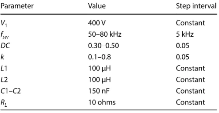
Parametric simulation studies were performed with Ansys-Electronics Desktop 2019R2 software, depending on the switching frequency (fs), switching duty cycle (DC) and coupling coefficient (kc) variables as seen in Fig. 5. Using the obtained data, both switching frequency and duty ratio were tried to be determined depending on the cou-pling coefficient between the primary and secondary coils. Technical data and step intervals used in parametric simu-lation studies are given in Table 1.
The change in output voltage according to switching frequency and duty cycle values while coupling coefficient is at a certain value is given in Fig. 6. Fluctuations depend-ing on the switchdepend-ing frequency are observed in low value key duty ratios. Since the coupling value is constant, this graph can only facilitate the determination of the switch-ing frequency value for a given duty cycle value.
Fig. 4 Mechanical parameters of the coils [20]
Fig. 5 Parametric simulation circuit
Table 1 Technical properties of the parametric simulation
Parameter Value Step interval
V1 400 V Constant fsw 50–80 kHz 5 kHz DC 0.30–0.50 0.05 k 0.1–0.8 0.05 L1 100 µH Constant L2 100 µH Constant C1–C2 150 nF Constant RL 10 ohms Constant
In a given switching frequency value, the loose cou-pling and tight coucou-pling effect can be explained by Fig. 7. According to this graph, if kc < 0.5, the voltage value trans-ferred to the secondary side by loose coupling effect is low value and in this case the efficiency is quite poor. When the kc > 0.5, the voltage value transferred by tight coupling effect can be kept at the desired level by duty cycle control.
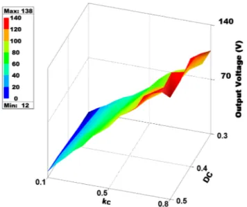
When the switching duty ratio is kept constant, the 3D voltage graph according to the change of switching fre-quency and coupling coefficient is given in Fig. 8. In this
graph, the switching frequency value can be determined according to the desired output voltage value for a certain value of the coupling coefficient.
For a constant value of the coupling coefficient, the variation of the voltage value depending on the switch-ing frequency values is more clearly described in Fig. 9. Thus, values below 50 kHz switching frequency for kc = 0.8 and DC = 0.45 have a poor result for efficiency. From this graph, the switching frequency value at which the voltage level is maximum can be determined as 65 kHz. Thus, very useful data can be obtained before the prototype design for the optimum switching frequency value according to the coupling coefficient by parametric simulations of the power electronics circuit.
In order to explain the effect of the magnetic coupling coefficient in more detail, the voltage variation graph
Fig. 6 Output voltage change based on switching frequency and
duty cycle
Fig. 7 Output voltage change depending on magnetic coupling
coefficient and duty cycle
Fig. 8 Output voltage change depending on magnetic coupling
coefficient and switching frequency value
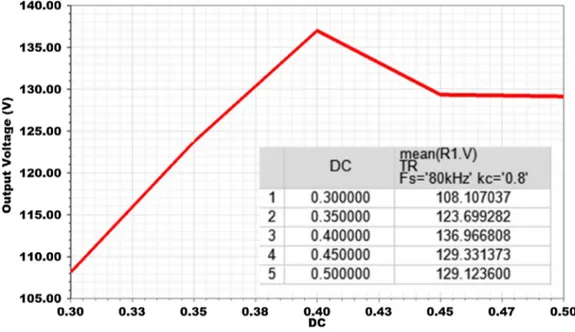
Fig. 9 Output voltage change depending on switching frequency
value when magnetic coupling coefficient and duty cycle are at constant values
in Fig. 10 can be examined. Where, while DC = 0.45 and
fs = 80 kHz, magnetic coupling values were simulated in specific steps in the range of 0.1–0.8 and voltage change was determined. In the simulation studies performed for proposed WPT system, the graphs were obtained accord-ing to the voltage value on a load connected to the output of the simulation circuit. Thus, the parametric data were obtained for the voltage value transferred to the load by the three phase coreless transformer design.
The relationship between the change in duty cycle value and the output voltage value in the inverter circuit can be explained by the graph in Fig. 11 when fs = 80 kHz and kc = 0.8. When DC = 0.4, voltage transfer is realized at maximum value, thus system efficiency is at highest val-ues. It is seen that the duty cycle value changes the trans-ferred output voltage value in the three phase two level inverter circuit, and the maximum value of the voltage can be determined with the help of this graph.
3.2 Ensemble learning
The ensemble learning method helps improve machine learning results by combining multiple learning model. The aim of the community model is that a group of learn-ing methods come together to form a strong learner, thereby increasing the accuracy of the model. In the prediction study with machine learning techniques, the main reasons for the difference in actual and predicted values are caused by noise and variance. These factors are reduced by the ensemble method [21, 22].
In this study, ensemble decision trees were used. Bag-ging and boosting methods are used to create ensemble decision trees. In application, Bagging (Bootstrap Aggre-gation) was used to reduce the variance of the decision tree. fs, kc and DC values were used as input and effi-ciency estimation was performed. 105 data obtained as a result of the simulation were separated into 80% training and 20% test. As a result of the application, the estimation error was calculated as 0.15 using Root Mean
Fig. 10 Output voltage change due to magnetic coupling
coeffi-cient value when switching frequency and duty cycle are constant values
Squared Error (RMSE) metric. The actual and estimated values of the 21 test data used are shown in Fig. 12.
4 Conclusion
In this study, three phase WPT circuit which can be used to charge electric vehicles wirelessly is proposed. The parametric simulation of the switching duty ratio and switching frequency values has been realized with Ansys-Electronics software depending on the change of the magnetic coupling coefficient of the WPT resonant circuit within the system. With the obtained parametric data, 3D and 2D graphs were created, thus the power electronics circuit parameters were determined based on the change of coupling coefficient. The effects of param-eter changes in nonlinear behavior which could not be determined with mathematical expressions were ana-lyzed. For future scientific studies, adaptive frequency and duty cycle control of the power electronics circuit is recommended to prevent breakage from the resonance due to changing magnetic coupling due to position and alignment errors of WPT system efficiency. Finally, the WPT efficiency is predicted by ensemble decision trees algorithm. The results show that the estimation with ensemble decision trees is quite successful. For the future studies, the proposed and predicted param-eters of the WPT system can be compared with the core transformer system to be designed with soft magnetic material.
Compliance with ethical standards
Conflict of interest The authors declare that they have no conflict of
interest.
References
1. Waseem M, Suhaib M, Sherwani AF (2019) Modelling and anal-ysis of gradient effect on the dynamic performance of three-wheeled vehicle system using Simscape. SN Appl Sci 1(3):225. https ://doi.org/10.1007/s4245 2-019-0235-8
2. Qiu C, Chau KT, Liu C, Chan CC (2013) Overview of wireless power transfer for electric vehicle charging. In: 2013 world elec-tric vehicle symposium and exhibition (EVS27), 17–20 Nov. 2013. pp 1–9. https ://doi.org/10.1109/evs.2013.69147 31
3. Furukawa H, Ishida H, Kyoden T (2019) Locating embedded iron bars for wireless power transmission through reinforced-con-crete wall. SN Appl Sci 1(9):966. https ://doi.org/10.1007/s4245 2-019-1018-y
4. Imura T, Okabe H, Hori Y (2009) Basic experimental study on heli-cal antennas of wireless power transfer for electric vehicles by using magnetic resonant couplings. In: 2009 IEEE vehicle power and propulsion conference, 7–10 Sept. 2009. pp 936–940. https ://doi.org/10.1109/vppc.2009.52897 47
5. Seungyoung A, Joungho K (2011) Magnetic field design for high efficient and low EMF wireless power transfer in on-line electric vehicle. In: Proceedings of the 5th European conference on antennas and propagation (EUCAP), 11–15 April 2011. pp 3979–3982
6. Takanashi H, Sato Y, Kaneko Y, Abe S, Yasuda T (2012) A large air gap 3 kW wireless power transfer system for electric vehi-cles. In: 2012 IEEE energy conversion congress and exposition (ECCE), 15–20 Sept. 2012. pp 269–274. https ://doi.org/10.1109/ ecce.2012.63428 13
7. Shin J, Shin S, Kim Y, Ahn S, Lee S, Jung G, Jeon S, Cho D (2014) Design and ımplementation of shaped magnetic-resonance-based wireless power transfer system for roadway-powered moving electric vehicles. IEEE Trans Ind Electron 61(3):1179– 1192. https ://doi.org/10.1109/TIE.2013.22582 94
8. Kim J, Kim J, Kong S, Kim H, Suh I, Suh NP, Cho D, Kim J, Ahn S (2013) Coil design and shielding methods for a magnetic reso-nant wireless power transfer system. Proc IEEE 101(6):1332– 1342. https ://doi.org/10.1109/JPROC .2013.22475 51
9. Miller JM, Onar OC, Chinthavali M (2015) Primary-side power flow control of wireless power transfer for electric vehicle charg-ing. IEEE J Emerg Sel Top Power Electron 3(1):147–162. https :// doi.org/10.1109/JESTP E.2014.23825 69
10. Villar I, Garcia-Bediaga A, Iruretagoyena U, Arregi R, Estevez P (2018) Design and experimental validation of a 50 kW IPT for railway traction applications. In: 2018 IEEE energy conversion
Fig. 12 Predicted and target
data 2 4 6 8 10 12 14 16 18 20 Data Index 0.3 0.4 0.5 0.6 0.7 0.8 0.9 1 Efficiency (%) Target Predicted
congress and exposition (ECCE), 23–27 Sept. 2018. pp 1177– 1183. https ://doi.org/10.1109/ecce.2018.85584 41
11. Mi CC, Buja G, Choi SY, Rim CT (2016) Modern advances in wireless power transfer systems for roadway powered electric vehicles. IEEE Trans Ind Electron 63(10):6533–6545. https ://doi. org/10.1109/TIE.2016.25749 93
12. Iruretagoyena U, Garcia-Bediaga A, Mir L, Camblong H, Villar I (2020) Bifurcation limits and non-ıdealities effects in a three-phase dynamic IPT system. IEEE Trans Power Electron 35(1):208– 219. https ://doi.org/10.1109/tpel.2019.29158 34
13. Kuzey S, Balci S, Altin N (2017) Design and analysis of a wireless power transfer system with alignment errors for electrical vehi-cle applications. Int J Hydrogen Energy 42(28):17928–17939. https ://doi.org/10.1016/j.ijhyd ene.2017.03.160
14. Dghais W, Alam M (2018) Wireless power transfer and ın-vehicle networking ıntegration for energy-efficient electric vehicles. Mobile Netw Appl 23(5):1151–1164. https ://doi.org/10.1007/ s1103 6-016-0779-4
15. Vallecchi A, Stevens C, Shamonina E (2017) Wireless power trans-fer in the presence of a conducting interface: an analytical solu-tion. In: IET conference proceedings
16. Choi SY, Gu BW, Jeong SY, Rim CT (2015) Advances in wireless power transfer systems for roadway-powered electric vehicles. IEEE J Emerg Sel Top Power Electron 3(1):18–36. https ://doi. org/10.1109/JESTP E.2014.23436 74
17. Moradewicz AJ, Miskiewicz RM, Sulima R, Sikora J (2016) Induc-tive energy transfer—3D space transformers analysis. In: 2016
progress in applied electrical engineering (PAEE), 26 June-1 July 2016. pp 1–7. https ://doi.org/10.1109/paee.2016.76051 20 18. Jiang W, Xu S, Li N, Lin Z, Williams BW (2015) Wireless power
charger for light electric vehicles. In: 2015 IEEE 11th ınternational conference on power electronics and drive systems, 9–12 June 2015. pp 562–566. https ://doi.org/10.1109/peds.2015.72035 33 19. Baroi S, Islam MS, Baroi S (2017) Design and simulation of a
wireless charging system for electric vehicles. In: 2017 2nd ınternational conference on electrical and electronic engineer-ing (ICEEE), 27–29 Dec. 2017. pp 1–4. https ://doi.org/10.1109/ ceee.2017.84129 15
20. Li W, Li X, Zhang J, Zhu G, Xie M, Li X (2015) Research on loosely coupled transformer’s structure for ICPT system. In: 2015 ınternational conference on ındustrial ınformatics—comput-ing technology, ıntelligent technology, ındustrial ınformation ıntegration, 3–4 Dec. 2015. pp 272–275. https ://doi.org/10.1109/ iciic ii.2015.149
21. Polikar R (2012) Ensemble learning. In: Zhang C, Ma Y (eds) Ensemble machine learning. Springer, Berlin, MA, pp 1–34 22. Sagi O, Rokach L (2018) Ensemble learning: a survey. Wiley
Inter-discip Rev: Data Min Knowl Discov 8(4):1–18
Publisher’s Note Springer Nature remains neutral with regard to