237 AURUM MÜHENDİSLİK SİSTEMLERİ VE MİMARLIK DERGİSİ
AURUM JOURNAL OF ENGINEERING SYSTEMS AND ARCHITECTURE
Cilt 4, Sayı 2 | Kış 2020
Volume 4, No 2 | Winter 2020, 237-244
ARAŞTIRMA MAKALESİ / RESEARCH ARTICLE LOW COST HIGH SPEED DATA ACQUISITION BOARD
FOR LABORATORY LASER SYSTEM
Osman N. UÇAN1
Altinbas University, Faculty of Engineering and Natural Sciences, Department of Electrical-Electronics Engineering, Istanbul. [email protected] ORCID No: 0000-0002-4100-0045
Oğuz BAYAT2
Altinbas University, Faculty of Engineering and Natural Sciences, Department of Software Engineering, Istanbul. [email protected] ORCID No: 0000-0001-5988-8882
Bara Saad ABDULHAKEEM3
Altinbas University, Graduate School of Science and Engineering, Electrical and Computer Engineering, Istanbul. [email protected], ORCID No: N/A during submission.
GELİŞ TARİHİ/RECEIVED DATE: 10.12.2018 KABUL TARİHİ/ACCEPTED DATE: 25.12.2020
Abstract
The Data Acquisition (DAQ) is the process of taking a real-world signal, like a voltage, towards the computer, for analysis, processing, storing or other data manipulation. The Computer DAQ systems utilized in laboratory research, manufacturing automation and in measurement and test. This work is aiming to implement and develop an accurate compact, low-cost DAQ system for laser systems that can be run and controlled by using an interface board connected to Computer and the user interface program. The interfacing board is based on use a low-cost microcontroller where Arduino Uno has been used in that purpose and the GUI (graphic user interface) program has been developed by using LabVIEW. The proposed DAQ system can control and acquiring DATA from laboratory laser system, which offer several functions like controls the intensity of laser, control the number of pulses during period of time, etc. The testing result show that the proposed system can control and acquiring data easily and effectively that can be utilized to controls different laser systems with variety of applications.
Keywords: Data Acquisition, DAQ, Laser system controller, Microcontroller, Arduino.
LABORATUVAR LAZER SİSTEMİ İÇİN DÜŞÜK MALİYETLİ YÜKSEK HIZLI VERİ TOPLAMA KARTI
Özet
Veri Toplama (DAQ), bilgisayara voltaj gibi gerçek bir sinyali alma işlemidir ve analiz, işleme, depolama veya diğer veri işleme işlemleri için kullanılabilir. Laboratuvarda kullanılan Bilgisayar DAQ sistemleri; araştırma, üretim otomasyonu ve ölçüm ve testte kullanılabilir. Bu çalışma lazer sistemleri için hassas, kompakt, düşük maliyetli
238
bir DAQ sistemi geliştirmek için geliştirilmiştir. Arayüz kartı, bilgisayara ve kullanıcı arayüz programına bağlıdır. Arduino Uno’nun bu amaçla kullanıldığı düşük maliyetli bir mikro denetleyici ve GUI (grafik kullanıcı arayüzü) programı LabVIEW kullanılarak geliştirilmiştir. Önerilen DAQ sistemi kontrol edebilir ve lazerin yoğunluğunu kontrol etmek gibi çeşitli işlevler sunan laboratuvar lazer sisteminden veri alınması, zaman aralığı vb. boyunca ölçebilir ve çeşitli uygulamalar için kullanılabilir.
Anahtar sözcükler: Veri toplama, DAQ, lazer sistemi kontrolü, mikrokontrolör, Arduino
1. INTRODUCTION
Generally, DAQ plugin boards are typical-function data acquisition devices that are suitable for calibrating signals. The function of DAQ is to measure electrical a or physical phenomenon like sound, pressure, temperature, voltage, current, etc. computing-based data acquisition has used a grouping of hardware, software, and a computing system to get measurements. As each DAQ system is identified by its application specifications, each system offers a typical purpose of analyzing, acquiring, and providing information. DAQ systems include sensors, signals, actuators, DAQ devices, signal conditioning, and application software (Sumathi, Surekha, 2007).
The area of DAQ includes a variety of activities. At it is simplest level, it includes reads the electrical signals right into a computer making use of Several type of sensor. Such signals will possibly represent the physical process state such as shape and size of a manufactured component, orientation and position of machine tools, heating system temperature, etc. The acquired data will possibly have displayed, printed or stored. often the data must be processed or analysed in several ways so as to make additional signals for managing external devices or for interfacing to many Some other computers (Kanani, Thakker 2015). This would possibly include manipulating the static indication, however it’s also often important to deal at time-varying signals likewise. Several systems will possibly involve data to be collected over time spans of several weeks or days. Some other will require short breaks of extremely high-speed data acquisition – possibly at rates of nearly thousands of indications per second. The most main reason for making use of the PC for data acquisition and controls now days is that there’s a large and increasing pool of scientists, programmers and engineers that are familiarized with the PC (James, 2000).
The work is aiming to design a low cost multi-channel data acquisition system which can be used for laser laboratory application.
2. LITERATURE REVIEW
Camargo et al (2015) made a DAQ System making use of Arduino for the integrating of sensors to the computer. The system had been qualified for poultry coops environment external and internal conditions (humidity and temperature) measurement.
Kashyap (2015), has Designed a Low Cost Multi Channel DAQ System concerning Meteorological Application. The proposed DAQ had been designed to acquiring barometric pressure, temperature, light intensity, altitude and humidity direct from the environment and save the data in a computer concerning
239 AURUM MÜHENDİSLİK SİSTEMLERİ VE MİMARLIK DERGİSİ
AURUM JOURNAL OF ENGINEERING SYSTEMS AND ARCHITECTURE
future use. The sensors have been interfaced with microcontroller based ATmega328 that performs the acquiring purpose and data logging.
Simões and Souza (2016), has developed a cheap computerized DAQ system for urban sites humidity and temperature monitoring based on IoT (internet of things). They developed a computerized DAQ system that communicates the interoperability and interaction of the humidity and temperature sensors via the internet. The excremental results showed that the use of IoT enhanced the effectivity of automatic decision making for the system.
Misiruk et al (2016) established a DAQ System depending on Arduino Platform for Measurements of Langmuir Probe Plasma. Arduino Nano has-been employed to design this simple DAQ system and Bluetooth has-been employed for data transmitting. An Android program has-been established for data analysis and visualization. The system has-been successfully implemented to obtain Langmuir probe using a hollow anode measurements data.
3. DATA ACQUISITION SYSTEM 3.1 DAQ Structure
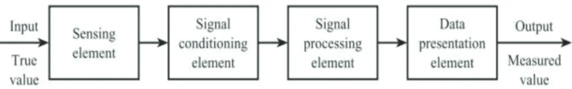
A typical DAQ system consists of a number of components like computing unit, signal conditioning unit, sensing unit and monitor unit. The DAQ gets physical or environmental parameters direct from the real world, runs signal conditioning into it and computes the real value for monitor purpose. Fig.1 illustrated the block diagram of DAQ. (Kashyap, 2015).
Fig. 1. Block diagram of DAQ (Kashyap, 2015). 3.2 DAQ types
DAQ can be generally classified to about three different categories: computer based DAQ, DAQ based on separate acquisition devices, and Modular DAQ. Figure 2 shows the about three types of DAQ system (Kashyap, 2015).
240
Osman nuri ucan, Oguz Bayat, Baraa saad aBdulhakeem
3.2 DAQ types
DAQ can be generally classified to about three different categories: computer based DAQ,
DAQ based on separate acquisition devices, and Modular DAQ. Figure 2 shows the about
three types of DAQ system [5].
(a)
Fig.2. Block diagram of, (a) DAQ based PC, (b)DAQ based on independent acquisition
instruments, (c) Modular DAQ [5].
4. PROPOSED DAQ STRUCTURE
The proposed DAQ is consisted from three main components: Sensors, Digital-Analog
input/output (DA-IO), Controller and graphic user interface (GUI). Figure 3 shows the block
diagram of proposed DAQ system.
Fig.3. block diagram of proposed DAQ system
4.1 Sensors
Sensors are the first input element used in checking out physical quantities (for example
position, force or temperature) towards a DAQ system. They're commonly used to
determine analogue signals. In this work we have used photo diode in order to receive laser
signal and show the signal in GUI.
4.2 Digital-Analog Input/output (DA-IO)
The data received from the field is either analog or digital. The digital inputs tested
Sensors
DA-IO
Controller
GUI
(b)
(c)
Fig.2. Block diagram of, (a) DAQ based PC, (b)DAQ based on independent acquisition instruments, (c) Modular DAQ (Kashyap, 2015).
4. PROPOSED DAQ STRUCTURE
The proposed DAQ is consisted from three main components: Sensors, Digital-Analog input/output (DA-IO), Controller and graphic user interface (GUI). Figure 3 shows the block diagram of proposed DAQ system.
3.2 DAQ types
DAQ can be generally classified to about three different categories: computer based DAQ,
DAQ based on separate acquisition devices, and Modular DAQ. Figure 2 shows the about
three types of DAQ system [5].
(a)
Fig.2. Block diagram of, (a) DAQ based PC, (b)DAQ based on independent acquisition
instruments, (c) Modular DAQ [5].
4. PROPOSED DAQ STRUCTURE
The proposed DAQ is consisted from three main components: Sensors, Digital-Analog
input/output (DA-IO), Controller and graphic user interface (GUI). Figure 3 shows the block
diagram of proposed DAQ system.
Fig.3. block diagram of proposed DAQ system
4.1 Sensors
Sensors are the first input element used in checking out physical quantities (for example
position, force or temperature) towards a DAQ system. They're commonly used to
determine analogue signals. In this work we have used photo diode in order to receive laser
signal and show the signal in GUI.
4.2 Digital-Analog Input/output (DA-IO)
The data received from the field is either analog or digital. The digital inputs tested
Sensors
DA-IO
Controller
GUI
(b)
(c)
Fig.3. block diagram of proposed DAQ system 4.1 Sensors
Sensors are the first input element used in checking out physical quantities (for example position, force or temperature) towards a DAQ system. They’re commonly used to determine analogue signals. In this work we have used photo diode in order to receive laser signal and show the signal in GUI.
4.2 Digital-Analog Input/output (DA-IO)
The data received from the field is either analog or digital. The digital inputs tested continuously. In other hand, the analog input is initially transformed into digital received by using A/D converter. These signals are usually in form of current or voltage. By assist of calibration it can be transform to actual form.
241 AURUM MÜHENDİSLİK SİSTEMLERİ VE MİMARLIK DERGİSİ
AURUM JOURNAL OF ENGINEERING SYSTEMS AND ARCHITECTURE
4.3 Controller
The controller can be used as the communicator between the PC and real world. Based on the sensors calibration factor, the signal will be converted and gain the actual output. This work implements a low cost DAQ by used low cost microcontroller. In this work we have used Arduino which is commonly used microcontroller unit because it efficient and low cost. We have used Arduino Uno microcontroller. This board is based on the ATmega328P. It has fourteen digital I/O pins (where six pins can be used as PWM outputs), six analog inputs, an ICSP header, a 16MHz quartz crystal. It has everything necessary to support the microcontroller. The developing code for Arduino is very easy. Meaning, Arduino microcontroller has many advantages of less expensive, user friendly and can make solution with it and got accurate results.
4.4 GUI
The GUI is showing the calibrated signals on the computer software or on display. In this work the GUI is designed by used LABVIEW (Laboratory Virtual Instrumentation Engineering Workbench). The LabVIEW toolkit assists to perfectly interface the Arduino microcontroller with LabVIEW software. by used LabVIEW, we are able to acquire data or control the Arduino. Figure 4 (a) shows the block diagram of program structure in LabVIEW. In this work we have designed a program that mange the laser operation such as laser intensity and pulses duration via controlled the Arduino microcontroller, figure 4 (a) shows the block diagram of program structure in LabVIEW. The GUI has been designed to be simple and it includes the adjusting tuner to make desired function, and it contain display in order to show the laser signal result in real time. Figure 4(b) shows the GUI that can be controlled by users.
(a) (b)
242
The operation of proposed system that the user can control the intensity of laser by converted the frequency tuner in GUI and can also controlled make laser shot as pulses with selected pulse duration via used Duty Cycle tuner in GUI. The microcontroller controlled the laser function. In other side, the photo diode can receive the laser signal and then transmitted electric signal to microcontroller which stores that value in its ROM. Then the microcontroller will transfer data to LabVIEW by using VISA tool. Figure 5 illustrated the proposed DAQ system structure.
Fig.5. The proposed DAQ system structure 5. RESULT AND DISCUSSION
The proposed DAQ system (figure 6) has been tested in order to test the accuracy of operation controlled and gathering signals, and ease of use.
(a) (b)
243 AURUM MÜHENDİSLİK SİSTEMLERİ VE MİMARLIK DERGİSİ
AURUM JOURNAL OF ENGINEERING SYSTEMS AND ARCHITECTURE
The operation test DAQ shows that the system run smoothly, and the controlling orders run fast without any problem. The GUI is simple and easy to use and any one with little information can learn how to use it. The DAQ gathering laser signals by used photo diode, we have compared it with an authorized 200MHz digital oscilloscope type (UNI-T) model (UT2202C). Figure 7(a) and 7(b) shows the laser signal in oscilloscope and GUI of DAQ respectively that recorded for same laser pulses.
(a) (b)
Fig.5. the laser signal recorded from (a) digital oscilloscope, (b)proposed system GUI.
As shown from figure 7(a) and 7(b), the laser signal recorded by the proposed system is relatively identical to laser signal recorded by the professional digital oscilloscope. This provide that the DAQ have high accuracy with some advantage that it can recorded the signal continuously in addition to controlling device and see the results instantly.
6. CONCLUSION
In this paper we propose a DAQ system that used for control and gathering signals for laboratory laser systems. The proposed DAQ has been designed with low cost component where Arduino Uno used as a microcontroller. The experimental results show that the proposed DAQ system run smoothly and it easy to use. The laser signal recorded by DAQ is relatively same as the signal recorded by professional digital oscilloscope, in addition to the signal display in real time without any delay so the user can modify the setting and view result Instantaneously. The system was successfully implemented as proposed and results were obtained as expected. The application of proposed system can be utilized in make a DAQ system for old devices or for new fabricated laser devices.
244
7. REFERENCES
Camargo, T.F B., C.T. Prado, M.R. Coutinho, M. Higa, W.A.S. Conceição, and C.M.G. Andrade. 2015.
Use of Scilab and Arduino for data acquisition environmental. Electronic Measurement & Instruments (ICEMI), 12th IEEE International Conference on, DOI: 10.1109/ICEMI.2015.7494222.
James, K. 2000. PC Interfacing and Data Acquisition: Techniques for Measurement, Instrumentation and
Control. Elsevier, ISBN: 9780080513652.
Kanani, N. and M. Thakker. 2015. Low Cost Data Acquisition System Using LABVIEW. 2nd International
Conference on Multidisciplinary Research & Practice, IJRSI, 3(1), 67-70.
Kashyap, N. 2015. Design of Low Cost Multi Channel Data Acquisition System. Master Thesis in Electronics
and Communication Engineering, Department of Electronics and Communication Engineering, National Institute of Technology, Rourkela, Odisha.
Misiruk, I.O., O.I. Timoshenko, and V.S. Taran. 2016. Data acquisition system based on Arduino platform
for Langmuir probe plasma measurements. Applied Physics and Engineering (YSF), II International Young Scientists Forum on, IEEE, DOI: 10.1109/YSF.2016.7753818.
Simoes, N.A.V., and G.B. de Souza. 2016. A low cost automated data acquisition system for urban sites
temperature and humidity monitoring based in Internet of Things. Instrumentation Systems, Circuits and Transducers (INSCIT), International Symposium on, IEEE, DOI: 10.1109/INSCIT.2016.7598189.
Sumathi, S. and P. Surekha, P. 2007. LabVIEW based Advanced Instrumentation Systems. Springer-Verlag