Primljen / Received: Ispravljen / Corrected: Prihvaćen / Accepted: Dostupno online / Available online:
Authors: 1.10.2018. 24.5.2019. 10.6.2019. 10.12.2019. Research Paper Turgay Cosgun, Cumhur Cosgun, Abdulrauf Kanishka, Atakan Mangir, Baris Sayin, Ahmet Murat Türk
Seismic load tests on exterior beam-column connections of existing RC
structures
Recommendations for enhancement of performance of RC beam-column joints under seismic effects are presented in this study. The aim is to evaluate the use of low-strength concrete with plain bars without stirrups in the joints. An additional aim is to study behaviour of joints in the aforementioned conditions under cyclic loading. Five specimens with various reinforcement configurations were produced and tested in the experimental process. Based on results obtained in the study, it is concluded that the stirrup arrangement in the joints, and the use of at least 90-degree hooks in longitudinal reinforcement of beams, are critical parameters for the performance of existing structures. Key words:
RC beam-column joint, low-strength concrete, cyclic loading, experimental testing
Prethodno priopćenje Turgay Cosgun, Cumhur Cosgun, Abdulrauf Kanishka, Atakan Mangir, Baris Sayin, Ahmet Murat Türk
Ispitivanja rubnih spojeva greda-stup postojećih AB konstrukcija na djelovanje
potresa
U radu su izneseni prijedlozi za poboljšanje svojstava spojeva greda-stup postojećih AB konstrukcija uslijed potresnog djelovanja. Analizirana je uporaba betona niske čvrstoće, glatkog armaturnog čelika bez spona u spojevima te je ispitano ponašanje spojeva u uvjetima pod cikličnim opterećenjem. U okviru eksperimentalnog istraživanja proizvedeno je i ispitano pet uzoraka s različitim rasporedom armature. Na temelju rezultata zaključeno je da su kritični parametri koji određuju svojstva postojećih konstrukcija, raspored spona u spojevima i upotreba kuka za sidrenje uzdužne armature koje su savijene pod kutom od najmanje 90°. Ključne riječi:
spoj AB greda-stup, beton niske čvrstoće, ciklično opterećenje, eksperimentalno ispitivanje
Vorherige Mitteilung Turgay Cosgun, Cumhur Cosgun, Abdulrauf Kanishka, Atakan Mangir, Baris Sayin, Ahmet Murat Türk
Prüfung von Balken-Pfeiler-Kantenverbindungen bestehender
Stahlbeton-Strukturen bei Erdbebeneinwirkung
In dieser Studie werden Vorschläge zur Verbesserung der Eigenschaften von Stahlbeton-Balken-Pfeilerverbindungen infolge von Erdbebeneinwirkung gemacht. Ziel ist es, die Verwendung von glattem Stahlbeton einer geringen Festigkeit ohne Spanner in den Verbindungen zu bewerten. Es ist auch beabsichtigt, das Verhalten der Verbindungen unter Bedingungen unter zyklischer Belastung zu untersuchen. Im experimentellen Verfahren wurden fünf Proben mit unterschiedlicher Anordnung der Bewehrung hergestellt und geprüft. Aufgrund der Ergebnisse wird der Schluss gezogen, dass die Anordnung der Spanner in den Verbindungen und die Verwendung von Haken unter einer mindestens 900-Längsbewehrung kritische Parameter für die Bestimmung der Eigenschaften bestehender Konstruktionen sind. Schlüsselwörter:
Seismic load tests on exterior beam-column
connections of existing RC structures
1Assoc.Prof. Turgay Cosgun [email protected]
2Cumhur Cosgun, PhD. CE [email protected]
3Abdulrauf Kanishka, MCE. [email protected]
4Assist.Prof. Atakan Mangir [email protected]
1Assoc.Prof. Baris Sayin [email protected] Corresponding author
5Assoc.Prof. Ahmet Murat Türk [email protected] 1Istanbul University-Cerrahpasa, Turkey
Department of Civil Engineering
2Marshall University, USA
College of Information Technology and Engineering
3Istanbul University, Turkey
Institute of Graduate Studies in Science and Engineering
4Istanbul Medipol University, Turkey
School of Engineering and Natural Sciences
1. Introduction
In modern and developed countries, the use of high-quality concrete and ribbed rebars in RC structures is quite frequent, especially in the countries that are prone to earthquakes. However, the quality of concrete used in the building structures of developing countries is lower than that used in developed countries. The use of plain rebars was abandoned years ago in many developed countries around the world. Even though plain reinforcement is not preferred in the newly constructed structures, plain rebars are still found in the most of the existing structures. Considerable amount of research is carried out worldwide with regard to the repair and strengthening of RC structural elements. However, the usual concern is that most of the studies might not be valid for existing structures due to low concrete strength and plain rebars. Therefore, the properties relevant for the studied building stock are important for studies involving typical applications as highlighted above.
Some experimental studies that deal with the beam-column joints of substandard reinforced-concrete buildings, and some enhancement methods with new materials and techniques have also been presented in the literature [1-2]. In these studies, the effects of carbon fibre–reinforced polymer (FRP) composites for strengthening the beam-column joints are shown through 3D frame testing (four full-scale three-dimensional reinforced concrete frames), which represents substandard reinforced concrete buildings. Some analytical seismic performance predictions, with the current seismic assessment and strengthening guidelines, are presented and compared with test results. As stated in the related studies, the complexity of the problem and the variety of parameters make the subject challenging for the engineering. A realistic representation of the actual quality of material (i.e. low-strength concrete), reinforcement details (i.e. use of plain bars, stirrup configuration, and anchorage of beam bars), types of deficiencies and the corresponding failure modes, are the major issues that need to be addressed.
The performance of framed structures depends not only upon individual structural elements but also on the integrity of their joints. When a structure is located in a non-seismic zone and designed for gravity loads only, the design check for joints might be not critical and, thus, it is usually not performed. However, catastrophic failures related to joints were reported in past earthquakes, especially in several recent earthquakes registered in Turkey [3-5]. The beam-column joint undergoes serious stiffness and strength degradation when subjected to earthquake loads. One of basic assumptions of the frame analysis is that the joints are strong enough to resist external effects (moments, axial forces and shear forces) generated by the loading, and to transfer the forces from one structural member to another (usually from beams to columns). It is also assumed that joints are rigid, and that members combining at a joint deform (rotate) by the same angle [6]. In most cases, joints of framed structures are subjected to the most critical loads under seismic conditions. Therefore, the joints are crucial zones in terms of transferring forces and moments effectively through the connecting elements, such as beams and columns. Accordingly, the beam-column joint in a multi-storey frame transfers the loads
and moments at the ends of the beams to the columns. A beam-column joint is defined as the portion of beam-column within the depth of the deepest beam that frames into column [7]. The behaviour of a beam-column joint is influenced by several variables such as concrete strength, arrangement of joint reinforcement, size and quantity of beam/column reinforcement, axial load in the column, and bond between concrete and longitudinal bars in beam/column. In most existing structures in Turkey, beam-column joints are characterized by insufficient transverse reinforcement, low strength concrete, and plain rebars. A limited number of studies can be found in the literature on the behaviour of this type of beam-column joints in existing structures. Therefore, behaviour of these structural components is not well defined and known. In this study, the aim is to investigate behaviour of RC beam-column joints under the influence of cyclic and constant axial loads. Numerous studies have been carried out since 1960s to understand the RC beam-column behaviour under earthquake effects. The initial research on beam–column joints was performed by Hanson and Connor [8]. Then the results obtained by these authors were further improved by various researches [9-12]. The most recent studies on beam–column connections have been made by Kim et al., Choi and Kim, Joyklad et al. and Kim and Yu [13-16]. Due to the lack of studies focusing on the behaviour of beam-column joints, and considering inadequacies and mistakes in application in Turkey, it is still an important question whether the findings obtained for structures in developed countries could be validated using the data from the buildings. Specifically, the studies conducted in recent years on the behaviour of column-beam connections under the influence of seismic action represent a significant advantage for proper realisation of this objective.
Hanson and Conner [8] conducted one of initial experimental studies on the behaviour of beam-column joints. In their experiments, Ehsani and Wight [17] observed that transverse beams impose additional shear on the joint and affect behaviour of the joint. In the study of Pessiki et al. [18], none of the shear reinforcement was placed in the joint area, and continuous reinforcement was located at the bottom of the joint area. Their testing has revealed intense shear cracks in the joint area in case of collapse. On the other hand, it was established during the tests carried out at the contact with the continuous longitudinal beam with subordinate reinforcement that the migrator came to the point of removing the longitudinal reinforcement under repeated loads. Kaku and Asakusa [19] observed that most of the joining area was dislocated when shear forces of beams were measured on specimens, and these shear forces amounted to less than 0.5 %. A sudden increase in shear deformation was observed when shear deformation exceeded 0.8 %. Beres et al. [20] observed that the shear resistance in concrete at the joint area was significantly higher than the shear resistance calculated using the equation given in ACI-ASCE 352R [21]. Tsonos et al. [22] tested twenty full-scale specimens in order to specify the excursion of reinforced exterior beam-to-column connections. Experimental findings showed that the use of oblique reinforcements crossed in the joint area is one of the most effective methods that could be employed to increase earthquake resistance at the outer joint area. In their experiments,
Higazy et al. [23] used six normal high-strength joints to reveal characteristics of the interior connection region under low axial pressure and axial pull. An average pressure of 42 MPa was found at high-strength node points. It was also observed that the axial load affects behaviour of the connection region for low column axial load, and there was a decrease in ductility, knot shear strength, and energy dissipation capacity, especially in the case of shrinkage. Tsonos [24] investigated three column-girder joining areas that included longitudinal ropes in the joining area. The test results were compared to the results obtained on samples built using the longitudinal combination shearing equipment according to the provisions of CEB, Eurocode 8 and NZS 3101 [25-27]. The comparative evaluation implied that longitudinal rebars are an effective method for increasing earthquake resistance in the joint area. There are very few analytical models on the development on shear and peel deformations in the joint region, i.e. only a few models have been proposed thus far. The behaviour of the beam-column joint area was firstly described by Park and Paulay [28] and, later on, Paulay et al. [29] explored this behaviour in greater detail. Pessiki et al. [18] noted that most of the framework analysis programs consider the junction area as fully rigid, and presented an alternative approach. Hoffmann et al. [30] solved the problem indirectly by examining the modelling problem of the joint region with the knot fitting of the properties of the knotted frame elements. The shear capacity of the joint area was reduced thus decreasing the capacity of bending elements. The formulation presented in ACI-ASCE 352R [21] was employed in the analysis to calculate the junction area capacity. The same approach was utilized to peel problem in the central joint area of longitudinal reinforcements in RC beams. The discontinuity of the longitudinal reinforcement was considered by calculating an equivalent moment for the torque moment capacity – the bending moment at the time when the longitudinal reinforcement began to peel off. Bracci et al. [31] proposed a model based on the principle of reduction in column and beam stiffness by multiplying the moments of inertia and some coefficients. The coefficients were derived from engineering approach
or experimental results. In this approach, proposed by Hoffmann et al. [30], the joint problem was solved indirectly. Fleury et al. [32] presented a model focusing on the study of reinforcement, concrete, and adherence-peeling behaviour. Finite element and extended models that consider shear and adherence-stripping forces can also be found in the literature [33, 34]. Hegger et al. [35] proposed a model for estimating the shear capacity and displacement mode of joint regions not designed for seismic effects. Hwang et al. [36] investigated the effects of stirrups placed in the junction area on the shear capacity of the junction zone. Three beam-column joints, i.e. the interior joint, exterior joint, and
corner joint, are shown in Figure 1. The joint area has to be appropriately designed to enable establishment of the framing system consisting of columns and beams at the desired level. An important proportion of the earthquake-induced damage occurs either in joints or in neighbouring zones. Due to strength or stiffness loss in beam-column joints, large lateral displacement in the frame and second-order effects might occur, which may lead to the collapse of the entire system.
Figure 1. Beam-column joint area in RC structures: a) Interior; b) Exterior; c) Corner [37]
Complex stripping and shear models have to be developed for joining zones [28, 38, 39]. Internal forces occurring in the joint area under earthquake loading are shown in Figure 2.
As shown in Figure 2, compressive and tensile forces generated in the column and beam are transferred by compressive and tensile stresses that occur in joints. Stresses occurring in joints are affected by reinforcement details in the joint area, hb/hc (height of beam cross-section/height of column cross-section) ratio, axial load ratio, and the quantity of stirrups in beam-column joints. Paulay et al. [29] proposed shear transfer mechanisms for joints known as diagonal strut and truss mechanisms, as shown in Figure 3. They considered that the strength of the diagonal strut controls the joint strength before cracking. When the joint shear becomes large, diagonal cracking occurs in the joint core and the joint reinforcement is subjected to load. Finally, the joint fails by concrete crushing in the joint core. It is specified in NZS
Figure 2. Internal forces under earthquake load: a) Corner beam-column joints; b) Interior beam-column joints [40]
3101 [41] that a large amount of transverse reinforcement is required in the joint in order to resist the dominant part of joint shear by truss mechanism, relying on the good bond stress transfer along longitudinal reinforcement [42].
Figure 3. Loading and transfer mechanisms: a) Lateral loading; b) Diagonal strut mechanism; c) Truss mechanism [40]
Severe reinforcing-bar bond deterioration in joints is assumed in ACI 318 and ACI 352 [3, 7]. Therefore, internal shear forces are resisted by the diagonal compressive strut of concrete only. Accordingly, the role of transverse reinforcement is to confine the core concrete. These conflicting concepts about the function of transverse reinforcement lead to different demand for hoop bars, as well as to the disparity in detailing criteria [36]. The real behaviour of structures might originate from the combination of the diagonal strut and truss mechanisms with partial longitudinal-reinforcement bond deterioration during cyclic loading [6].
2. Materials and methods
2.1. Specimen design
A series of tests for exterior beam-column joints were conducted in the experimental study. A total of five beam-column joint areas were produced in full scale with low concrete strength and, those areas represent joint regions with S220 quality steel reinforcement, which would negatively affect behaviour of the members. The performance of five specimens, which had different rebar configurations in joint areas, was investigated under the earthquake loads. Since the beam-column joint areas of the specimens are the regions of junction, the joints were designed to be weak, whereas the other areas were considered
to be strong, in the process of rebar design and planning according to the detailing criteria. In the testing, specimens were subjected to cyclic static loads, and the column axial load was kept constant during the testing (10 % of the column capacity). The rebar arrangement and strength of specimens were specified considering the current building stock in Turkey. The existing structures generally have plain bars (class S220) and they do not have an adequate stirrup arrangement in the joint regions. Details and general view of the specimens are given in Table 1 and Figure 4, respectively.
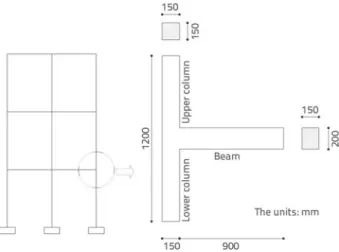
Figure 4. General view of the specimens
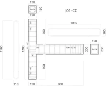
The predicted collapse mechanism is governed by the exceedance of shear capacity of the joint area or the slip of beam longitudinal rebars before reaching the bending capacity of the beam. Specimen reinforcement details are shown in figures 5 to 7. Beam and column cross-sectional dimensions were 150 mm × 200 mm and 150 mm × 150 mm, respectively, in the specimens prepared for testing. In the column and beam specimens, 4Ø14 plain rebars were used as longitudinal rebars. Ribbed rebars with a diameter of 8 mm were used as stirrups. The stirrup spacing was 100 mm in beams and columns. However, it was reduced to 50 mm in the support zones. The specimens were produced using a low-concrete quality to represent the actual concrete quality in existing structures. The compressive tests were performed on the cylinder samples obtained before the production of test specimens by a compressive press (capacity: 2000 kN) in laboratory.
Specimen Code Joint details
J01 (Reference) J01-CC Corner connection region is confined (C) and beam longitudinal rebars are upper and lower monolithically connected (C) to each other
J02 J02-0H-U Non-hooked (0H) and unconfined joint area (U)
J03 J03-90H-BU 90-degree hooks (90H), 2Ø12 rebars placed in the centre and beam-column joint is unconfined (BU) J04 J04-90H-CH 90-degree hooked (90H) joint area horizontally confined (CH) with stirrups
J05 J05-90H-CV 90-degree hooked (90H) joint area vertically confined (CV) with stirrups Table 1. Specimen details
Figure 5. Rebar details of control specimen J01
The results of the 28-days standard compressive strength of cylinder samples (100 mm × 200 mm) and concrete mixture proportions are given in Table 2. In order to ensure that the concrete used in the production of the specimens has the desired compressive strength, proper mixture ratios were determined and an average compressive strength of concrete specimens was obtained as 9 MPa for all specimens. The desired strength is selected below 10 MPa considering the condition of the current building stock in Turkey. The existing low-strength structures generally have an average concrete strength of approximately 10 MPa.
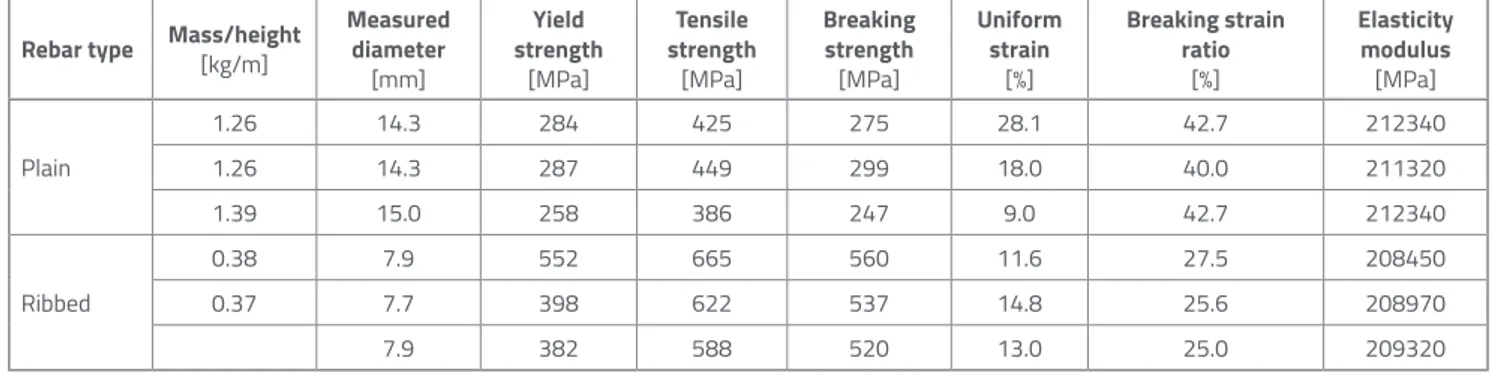
Steel rebar tensile tests were implemented in laboratory environment using the Amsler Tension Test Device (capacity: 200 kN) in accordance with the corresponding Turkish standard [43]. The average yield strength of the rebars used as reinforcement in the specimens amount to 276 MPa for plain bars and 444 Mpa for ribbed bars. Rebar tensile test results for longitudinal and transverse reinforcement are presented in Table 3.
Figure 7. Rebar details of specimens J04 and J05 Figure 6. Rebar details of specimens J02 and J03
2.2. Experimental setup
The test set-up was made with steel profiles and plates fixed to the lab floor with high strength bolts. The schematic view of test set-up is shown in Figure 8.
Figure 8. General view of test set-up
The specimens were tested under constant axial and cyclic loads with fixed axis and direction reversal connecting the upper and lower column parts to the test device with simple support. The beam was placed horizontally into the test device. Therefore, loads were applied in vertical direction, which allows upward pulling and downward pushing. The loading system and test specimen are shown in Figure 9.
Figure 9. Loading system
During an earthquake, structural elements are exposed to dynamic bending and shear forces, as well as to varying axial forces. However, this is difficult to simulate in laboratory environment, and loads are statically applied in experiments. The major advantage of static load tests is that the loading
Table 2. Compressive test results of concrete samples and concrete mixture proportions
Table 3. Tensile test results for longitudinal and transverse reinforcement
Sample Fracture load [kN] Stress [MPa] Loading rate [kN/s]
BCJ1 73.9 9.4 4.7
BCJ2 67.0 8.5 4.7
BCJ3 70.6 9.0 4.7
Average concrete compressive strength: 9.0
Concrete mixture proportions [kg/m3]
Concrete Cement Water aggregatesFine Coarse aggregates High-range water reducing admixture
Normal-weight 165 231 1414 271 1.8
Aggregate sizes (diameter): d < 9 mm 10 mm < d < 40 mm
Rebar type Mass/height [kg/m] Measured diameter [mm] Yield strength [MPa] Tensile strength [MPa] Breaking strength [MPa] Uniform strain [%] Breaking strain ratio [%] Elasticity modulus [MPa] Plain 1.26 14.3 284 425 275 28.1 42.7 212340 1.26 14.3 287 449 299 18.0 40.0 211320 1.39 15.0 258 386 247 9.0 42.7 212340 Ribbed 0.38 7.9 552 665 560 11.6 27.5 208450 0.37 7.7 398 622 537 14.8 25.6 208970 7.9 382 588 520 13.0 25.0 209320
behaviour can be observed step by step and over a wide range of time intervals, so that the element behaviour and damage can be monitored and recorded in a more detailed way. Therefore, the loading cycles were performed with step-by-step replacement of the specimen. Vertical loads that are applied to create bending moment and shear force, were exerted in the testing using the computer controlled UTEST hydraulic overrun. The cyclic vertical load was applied to the 150 mm x 200 mm cross-section of the beam. The hydraulic lifter had a load capacity of 100 kN to provide for the pushing and pulling and it had a total displacement capacity of 300 mm. All tests were performed with displacement control and the displacement range of the UTEST hydraulic loader in the control system was defined as ±52.5 mm. The loads were applied for both pushing and pulling direction. Moreover, the specimen feet were placed on the ends of the column of the sample in the supports providing roller support conditions in the loading system. The specimen, the load meter, and the hydraulic jack were used to apply the axial load. Supports made of sheet metal, which are able to meet the axial load in three zones of the column, were used. Then the hydraulic jacket load was used to apply axial force to the specimen. At the beginning of the design stage, the concrete compressive strength was assumed as 10 MPa, and the axial load was calculated according to Eq. (1). In the equation, n, N, fc’, b
and h are axial load ratio, axial load, compressive strength of concrete, column width and height, respectively.
(1) The axial force was applied by means of a hydraulic jack with a capacity of 100 kN. During the tests a constant axial load of 22.5 kN was applied to the specimen. This axial load corresponds to 10 % of the axial load capacity according to the concrete strength of 9 MPa. During the test, the axial load level was checked by means of a 100 kN capacity UTEST (CLP-100CMP) loader placed between the specimen and the jack and the axial load was maintained at 22.5 kN using the jack. In order to distribute the axial load uniformly onto the specimen, a flat steel sheet (150 mm × 150 mm) 10 mm in thickness was placed at the end of the specimen, where the axial force was applied and roller support conditions were also formed by a steel mechanism placed at the specimen ends (Figure 10).
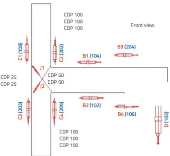
The measurement system consisted of strain gauges, Novotechnic and Opkon displacement gauges, UTEST loader, and internal load cell. The data collected from these devices were sent to three TESTBOX-1001 data collectors. The data were then transferred to the computer for processing. Eleven displacement gauges were placed on each specimen. The names and locations of the displacement gauges are shown in Figure 11. Each displacement gauge is represented by a code.
Figure 10. Axial load application point (left) and roller supports at specimen ends (up and down)
Figure 11. Displacement gauges on the specimen
Displacement gauges with 100 mm and 25 mm measurement lengths were placed at various points along the column and beam to determine average cross-sectional curvatures, and to check the slip of longitudinal reinforcement. The gauges
are classified as C type (C1, C2, C3 and C4), B type (B1, B2, B3 and B4) and J type (J1 and J2). The gauge types represent the locations where they were placed on the column, beam and joint, respectively. The characteristics and locations of displacement gauges placed on specimens are given in Table 4.
The displacement gauges were attached to specimens by L shaped metal plates and bolts (diameter: 5 mm). The embedded length of the bolts in concrete was 7 cm. Two displacement gauges were placed on the joint area at an angle of 45 degrees to obtain shear deformations of the joint zone. The hydraulic jack consists of an internal load cell and a built-in displacement gauge. The operation of the system, in other words, provision of main displacement data, is controlled by this built-in displacement gauge. Since the tests were performed by displacement control, the main displacement is also checked by a displacement gauge (D), which was placed at the bottom end of the beam. The aforementioned displacement gauge locations and establishment of the test system are represented in Figure 12.
Figure 12. Test setup and displacement gauges
2.3. Loading pattern
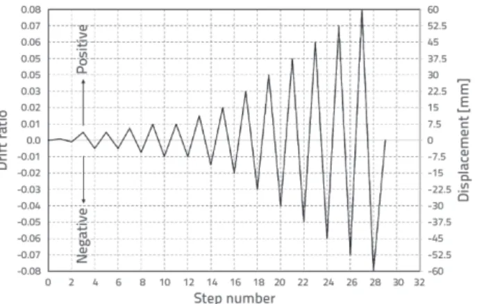
The tests were implemented as static displacement controlled operations. Repeated vertical displacements were applied to the specimen to simulate earthquake loading. Since experimental procedures were planned as sequential steps, the mechanical response and state of each specimen were evaluated and the next loading step was carried out. This approach enabled accurate observation and assessment of specimen behaviour, such as the damage occurrence mechanism. Therefore, it was performed to investigate the damage state of the specimen between the loadings and the time was not a limitation for this task. Loading steps were determined by selecting certain values of the drift ratio. The test piston speed was 0.05 m/s. The loading pattern and plan are presented in Figure 13 and Table 5, respectively. The final steps of the loading plan could not be completed in some tests due to high damage of the joint areas. “0.08“ drift ratio was achieved only in the first specimen test.
Figure 13. Cyclic loading history
Displacement gauge (max. measurement length) [mm] Locations Function
D (150) Bottom of beam’s end Beam’s vertical displacement
C1 (25)
Upper column Upper column moment-curvature
C2 (100) C3 (25)
Lower column Lower column moment-curvature
C4 (100) B1 (100)
At the top of the beam
Beam moment-curvature B3 (100)
B2 (100)
At the bottom of the beam B4 (100)
J1 (50)
On the Joint area Joint area diagonal measures J2 (50)
3. Results and discussion
The experimental vertical load, displacement and drift ratio relationships were determined using the load values obtained from the internal load cell of the loader and the displacement values measured at the tip of the beam. The characteristics of the specimens were given as load-displacement relationships. The experimental vertical load-carrying capacities (maximum load obtained during the tests) and the corresponding drift ratio of the specimens are presented in Table 6. The purpose of this table is to present the strength and structural performance of the joint area of the specimens.
Table 6. Drift ratio at maximum load
3.1. Load, displacement and drift ratio relationships
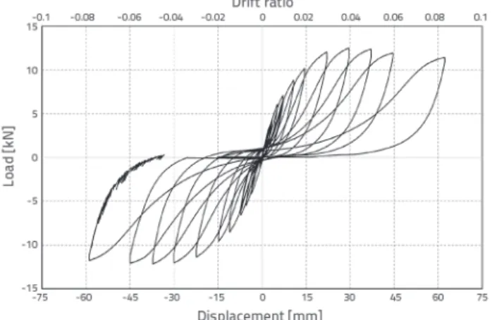
The elongation and shortening values in the pushing and pulling phases were noted for all specimens in the section where the first inclined shear crack occurred in the joining area. Even though the widths of the inclined shear cracks increased in the joining area, the shortening values continued consistently with the elongation data. Hysteresis curves present the load and displacement/drift
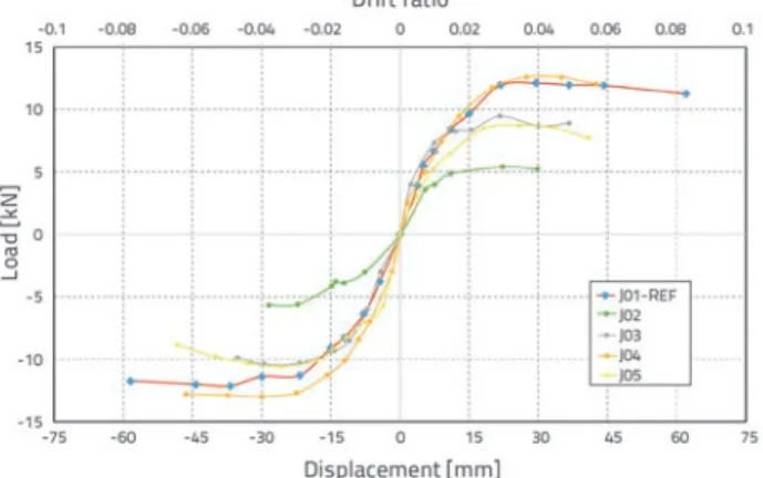
ratio relationships, which were measured as shown in figures 14-16. Additionally, peak points (envelopes) of the capacity curves of all specimens are shown in Figure 17. It is clear that the initial stiffness of all test specimens was almost the same, except for specimens J02 and J05.
Figure 14. Relationship of load vs. displacement/drift ratio for specimen J01
Figure 15. Relationship of load vs. displacement/drift ratio for specimens J02 (up) and J03 (down)
Table 5. Test loading plan
Steps Displacement [mm] Drift ratio
0 0 0 1-2 ±0.75 0.001 3-6 ±3.75 0.005 7-8 ±5.625 0.0075 9-12 ±7.5 0.01 13-14 ±11.25 0.015 15-16 ±15 0.02 17-18 ±22.5 0.03 19-20 ±30.0 0.04 21-22 ±37.5 0.05 23-24 ±45.0 0.06 25-26 ±52.5 0.07 27-28 ±60.0 0.08 29 0 0 Measuring length: 750 mm Specimen Push direction maximum load [kN] Drift ratio [%] Pull direction maximum load [kN] Drift ratio [%] J01 12.49 3.88 -12.13 -4.90 J02 5.42 2.97 -5.60 -2.96 J03 9.47 2.90 -10.40 -3.90 J04 12.60 3.66 -12.99 -4.00 J05 8.76 3.44 -10.58 -3.34
Figure 16. Relationship of load vs. displacement/drift ratio for specimens J04 (up) and J05 (down)
Figure 17. Load – displacement/drift ratio envelopes for five specimens
For the specimen J01, it was observed that as a result of subsequent displacements, the cracks in the joint area were not in harmony and consistency with the graphics obtained by the concentration and the increase of width. Evaluating the envelope curve of this experiment, it was determined that
the maximum load value of 12.3 kN was provided at the 4 % drift ratio. In addition, it is important to note that the sample load capacity did not fall below the range of 10 kN for pushing and pulling, and even drift ratio was 8 %. It seems that the requirements of J01 provide for the conditions described for the connection zones in Turkish seismic code [43]. Thus, relevant conditions are extremely important for the joint regions with regard to test results. For the specimen J02, it was observed that the concentration and increase in crack width showed that the correlation deteriorated. Considering the envelope curve of the experiment, it was determined that the maximum load value was 5.6 kN for a 2.96 % drift ratio. In the specimen J03, it was observed that the correlation partly deteriorated between the concentration and increase in crack width in the joint area. According to envelope curve of this experiment, the maximum load value amounted to 10.4 kN for a 3.9 % drift ratio. It was found for the specimen J04 that the concentration and increase in crack width was harmonic and that it showed correlation. In addition, it was determined that the maximum load was 12.99 kN for 4 % drift rate. It was also noted that the sample load capacity did not fall below the 10 kN in pushing and pulling motions even for 6 % drift rates. For specimen J05, it was observed that, as a result of subsequent displacements, the concentration and increase of crack width in joint area were not in harmony and lacked consistency, i.e. the correlation was not found. Considering the envelope curve for the experiment, it was determined that the maximum load was 10.58 kN for a 3.34 % drift ratio. The following practical implications and results were noted in the testing:
- J01 is the reference specimen with the details described for the relevant region in Turkish seismic code [40], longitudinal rebars of the beam did not slip but the concrete is locally crushed in the joining area.
- The specimen J02 is the weakest specimen in terms of reinforcement configuration. The concrete was locally crushed for the drift ratio of 0.0297 and the longitudinal reinforcement of the beam slipped. 6 mm separation occurred in the zone of split between the joining area and the beam surface.
For specimen J03, it was observed that the concrete was locally crushed in the connection zone, and the drift ratio was 0.039; longitudinal reinforcement of the beam slipped. Beam surface and the joining area revealed a separation of 15 mm and 12 mm for pushing and pulling, respectively.
For specimen J04, it was established that the concrete was locally crushed for a drift ratio of 0.04 in the joint region and that longitudinal reinforcement of the beam slipped. The joining area and the beam surface were separated by 2.7 mm and a fracture was also observed under the hook in the joint area.
For specimen J05, it was observed that the concrete was locally crushed in the joint area for a drift ratio of 0.0344 and that longitudinal reinforcement of the beam slipped. Moreover, the joining area and the beam surface were separated by 3.2 mm and the crust was found in the joint surface.
3.2. Failure modes of the specimens
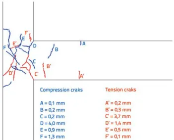
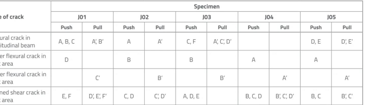
The push and pull cycles on the front and back sides of the specimens led to various cracks. In addition, schematic illustration of damage that occurred in experiments is provided to represent a realistic mechanism initiating failure in joint areas. Each crack on the cracked plane was processed and crack widths were defined by measuring the perpendicular distance between the two sides of the crack from the largest crack point. Failure modes and specifications such as shape, location and dimension properties of five specimens are presented in figures 18-20. The recorded crack widths are at the end of the steps, and they represent the most critical state of the joint areas before finalizing the tests. The blue colour is used for push direction and the red colour is used for pull direction. The behaviour of junction areas was quantified and assessed, and it was revealed that the properties of cracks which appear in the beam-column joint area of the specimens differed depending on the displacement level. The cracks observed during the test series could be classified into flexural and shear cracks. The
classification and location properties of cracks with necessary definitions are presented in Table 7.
Figure 18. Location, shape and dimension properties of cracks for specimens J01
Figure 20. Location, shape and dimension properties of cracks for specimens J04 (left) and J05 (right) Figure 19. Location, shape and dimension properties of cracks for specimens J02 (left) and J03 (right)
4. Conclusions
The aim of the present study was to investigate experimentally the behaviour of beam-column joints of RC structures under cyclic loading. It is believed that the results of this study will help in understanding the behaviour of the joint regions of existing low-strength RC structures, so that proper decisions on the necessary assessment and strengthening method can be made. In other words, the test results show the deficiencies of structures that should be considered in the assessment process. In addition, the parts that should also be strengthened can be identified based on results of this study.
To examine the external RC beam-column junctions, five specimens were tested to determine the behaviour and response of the beam-column joints subjected to cyclic loading. The changes in characteristics of joint regions were analysed to gain insight into failure mechanism under cyclic loads. Failure modes of exterior beam-column joints produced with low-strength concrete, different reinforcements, and several configurations, are also provided. As a result of the tests, the significance of stirrup arrangement in the joints consisting of low-strength concrete, and the necessity of at least 90-degree hooking of the beam longitudinal rebars, are revealed. Furthermore, it was determined that the horizontal usage of the stirrups in the joint area increases performance better than the vertical application. A significant reduction in stiffness originating from cracks is an important parameter to consider and, the adherence and clamping of beam and column rebars should be provided for.
In addition, vital tasks include ensuring an appropriate shear strength in the joint region by proper stirrup arrangement to increase ductility. Accordingly, the following design principles and recommendations for assessment and strengthening are proposed:
- The strength of the joint areas should not be less than that of the joining elements. Thus, the repair of the joint area would not be frequently needed. In addition, the mechanism that significantly reduces the rigidity and strength of the structural system will be avoided.
- The decrease in strength of RC columns, which weakens the joint area, should be prevented. Beam-column joint zones should be considered as an extension of the columns and, therefore, column stirrups must be extended to include these critical regions.
- The behaviour of joint regions should be considered in the assessment of existing low-strength concrete structures. This can be achieved by decreasing the beam and column stiffness in the analyses or by modelling the joint region with similar deficiencies.
- The joint regions should also be taken into consideration in the retrofitting and strengthening procedures. The results show that the strengthening of beams or columns only will not help in increasing performance of structural systems. It is vital to provide the required shear strength and ductility to joint regions by using an appropriate strengthening method that is capable of providing protection in the case of an earthquake event.
Table 7. Crack types and locations in specimens Type of crack
Specimen
J01 J02 J03 J04 J05
Push Pull Push Pull Push Pull Push Pull Push Pull
Flexural crack in
longitudinal beam A, B, C A’, B’ A A’ C, F A’, C’, D’ D, E D’, E’
Upper flexural crack in
joint area D B B A A
Lower flexural crack in
joint area C’ B’ B’ A’ A’
Inclined shear crack in
joint area E, F D’, E’, F’ C, D C’, D’ A, D, E B, C, D B’, C’, D’ B, C B’, C’
REFERENCES
[1] Cosgun, C., Comert, M., Demir, C., Ilki, A.: Seismic Retrofit of Joints of a Full-Scale 3D Reinforced Concrete Frame with FRP Composites, Journal of Composites for Construction-ASCE, 23 (2019) 2, doi: 10.1061/(ASCE)CC.1943-5614.0000923.
[2] Cosgun, C., Comert, M., Demir, C., Ilki, A.: FRP Retrofit a Full Scale 3D RC Frame, 6th International Conference on FRP Composites in Civil Engineering, Roma-Italy, 2012.
[3] Tapan, M., Comert, M., Demir, C., Sayan, Y., Orakcal, K., Ilki, A.: Failures of structures during the October 23, 2011 Tabanlı (Van) and November 9, 2011., Edremit (Van) earthquakes in Turkey, Engineering Failure Analysis, 34 (2013), pp. 606-628
[4] Cosgun, C., Dindar, A.A., Seckin, E., Onen, Y.H.: Analysis of building damage caused by earthquakes in Eastern Turkey, Gradevinar, 65 (2013) 1, pp. 743-752
[5] Cosgun, C., Mangir, A.: Earthquake Performance of Collapsed School Building under Van-Tabanli (Mw=7.2) Earthquake, Challenge Journal of Structural Mechanics, 4 (2018) (4), pp. 159-175, doi: https://doi.org/10.20528/cjsmec.2018.04.004
[6] Subramanian, N.: Design of RC beam column joints, The Masterbuilder, (2015), pp. 136-148
[7] ACI-ASCE Committee 352: Recommendation for design of beam-column joints in monolithic reinforced concrete structures, American Concrete Institute, Farmington Hills, MI. pp. 37, 2002. [8] Hanson, N.W., Connor, H.W.: Seismic Resistance of Reinforced
Concrete Beam- Column Joints, Journal of the Structural Division - ASCE, 93 (1967), pp. 533–560
[9] Zhang, L., Jirsa, J.O.: A study of shear behavior of reinforced concrete beam– column joints, PMFSEL Report 82–1, University of Texas, Austin, USA, 1982.
[10] Sarsam, K.F., Phipps, M.E.: The shear design of in situ reinforced concrete beam– column joints subjected to monotonic loading, Magazine of Concrete Research, 37 (1985) 130, pp. 16–28 [11] Pantazopoulou, S., Bonacci, J.: Consideration of questions about
beam–column joints, Aci Structural Journal, 89 (1992) 1, pp. 27– 36
[12] Hwang, J., Lee, H.J.: Analytical model for predicting shear strengths of exterior reinforced concrete beam–column joints for seismic resistance, Aci Structural Journal, 96 (1999) 5, pp. 846–857 [13] Kim, J., LaFave, J.M., Song, J.: Joint shear behaviour of reinforced
concrete beam– column connections. Magazine of Concrete Research, 61 (2009) 2, pp. 119–132
[14] Choi, H., Kim, J.: Progressive collapse-resisting capacity of RC beam–column subassemblage, Magazine of Concrete Research, 63 (2011) 4, pp. 297–310
[15] Joyklad, P., Pimanmas, A., Dhakal, R.P.: Cyclic performance of beam–column joints with extended column fixed at base. Part I: experimental investigation, Magazine of Concrete Research, 64(2012) 9, pp. 807–80
[16] Kim, J., Yu, J.: Analysis of reinforced concrete frames subjected to column loss, Magazine of Concrete Research, 64 (2012) 1, pp. 21–33
[17] Ehsani, M.R., Wight, J.K.: Effect of beams and slab on behavior of reinforced concrete beam-to-column connections, Aci Structural Journal, 82 (1986) 2, pp. 188-195
[18] Pessiki, S.P., Conley, C.H., Gergely, P., White, R.N.: Seismic behavior of lightlyreinforced- concrete column and beam-column joint details, Technical Report NCEER- 90-0014, National Centre for Earthquake Engineering Research, 1990.
[19] Kaku, T., Asakusa, H.: Ductility estimation of exterior beam column subassemblage in reinforced concrete frames, ACI Special Publication: Design of Beam-Column Joints for Seismic Resistance, ACI, Farmington Hills, Michigan, pp. 167–186, 1991. [20] Beres, A., El-Borgi, S., White, R., Gergely, P.: Experimental results
of repaired and retrofitted beam-column joint tests in lightly RC frame building, Technical Report NCEER-92-0025, National Centre for Earthquake Engineering Research, 1992.
[21] ACI-ASCE Committee-352: Recommendations for design of beam-column joints in monolithic reinforced concrete structures, ACI 352R-76, ACI Journal, 73 1976 (7), pp. 375-393
[22] Tsonos, A.G., Tegos, I.A., Penelis, G.: Seismic resistance of type 2 exterior beamcolumn joints reinforced with inclined bars, Aci Structural Journal, 89 (1992) 1, pp. 3–12
[23] Higazy, E.M.M., Elnashai, A.S., Agbabian, M.S.: Behavior of beam column connections under axial column tension, Journal of Structural Engineering, 1996, doi: 10.1061/(ASCE)0733- 9445(1996)122:5(501)
[24] Tsonos, A.G.: Effect of vertical hoops on the behavior of reinforced concrete beamto- column connections, European Association for Earthquake Engineering, Journal of Earthquake Engineering., 14 (2000) 2, pp. 13–26
[25] CEB: Model code for seismic design of concrete structures, Bulletin d’Information CEB, No.165, Lausanne, 1985.
[26] Eurocode-8: Design of structures for earthquake resistance. British standard, EN 1998-1:2004, 2004.
[27] NZS-3101: Concrete Structures Standard – The design of concrete structures and Commentary on the design of concrete structures, Standards Association of New Zealand, Parts 1 and 2, Wellington, 1982.
[28] Park, R., Paulay, T.: Reinforced concrete structures. John Wiley & Sons, Inc., Newyork, 1975, pp. 769
[29] Paulay, T., Park, R., Priestley, M.J.N.: Reinforced Concrete Beam-Column Joints under Seismic Actions, ACI Structural Journal, 75 (1978) 11, pp. 585–93
[30] Hoffmann, G.W., Kunnath, S.K., Mander, J.B., Reinhom, A.M.: Gravity–loaddesigned reinforced concrete buildings: Seismic evaluation of existing construction and detailing strategies for improved seismic resistance. Technical Report NCEER92-0016, National Centre for Earthquake Engineering Research, 1992. [31] Bracci, J.M., Reinhom, A.M., Mander, J.B.: Seismic resistance of
R/C frame structures designed only for gravity loads, Part III experimental performance and analytical study of structural model, Technical Report NCEER-92-0029, National Centre for Earthquake Engineering Research, 1992.
[32] Fleury, F., Reynouard, J-M., Merabet, O.: Multicomponent model of reinforced concrete joints for cyclic loading, Journal of mechanical Engineering, 10 (2000), doi: 1061/(ASCE)0733- 9399(2000)126:8(804)
[33] Pantazopoulou, S.J., Bonacci, J.F.: On earthquake-resistant reinforced concrete frame connections, Canadian Journal of Civil Engineering, 21 (1994) 2, pp. 307–328
[34] Elmorsi, M.S.E.: Analytical modeling of reinforced concrete beam column connections for seismic loading, PhD thesis, McMaster University, Ontario, Canada, 1998.
[35] Hegger, J., Sherif, A., Roeser, W.: Nonseismic design of beam– column joints, ACI Structural Journal, 100 (2003) 5, pp. 654–664 [36] Hwang, S.J., Lee, H.J., Liao, T.F., Wang, K.C., Tsai, H.H.: Role of hoops
on shear strength of reinforced concrete beam-column joints, ACI Structural Journal, 102 (2005) 3, pp. 445–453
[37] Celep, Z., Kumbasar, N.: Introduction to Earthquake Engineering and Earthquake- Resistant Structure design, Istanbul, Turkey, 2000. [38] Paulay, T., Priestley, M.J.N.: Seismic design of reinforced concrete
and masonry buildings, John Wiley and Sons, New York, pp. 744, 1992.
[39] Paulay, T., Park, R.: Joints of reinforced concrete frames designed for earthquake resistance, Research Report 84-9, Department of Civil Engineering, University of Canterbury, Christchurch, New Zealand, 1984.
[40] Coşgun, C.: Retrofit of 3D Reinforced Concrete Beam-Column Joint with FRP, PhD thesis, Istanbul Technical University, Institute of Science and Technology, 2013.
[41] NZS-3101: Concrete Structures Standard, Part 1: The Design of Concrete Structures, Part 2: Commentary on The Design of Concrete Structures, Standards Council of New Zealand, Wellington, 2006.
[42] Kitayama, K., Otani, S., Aoyama, H.: Development of Design Criteria for RC Interior Beam-Column Joints, ACI SP-123 Design of Beam-Column Joints for Seismic Resistance, James O. Jirsa, Editor, American Concrete Institute, Michigan, 1991, pp. 97–123 [43] Turkish Earthquake Code (TEC): Specification for buildings to
be built in earthquake regions, Ministry of Public Works and Settlement, Government of the Republic of Turkey, Ankara, 2007.