Interpretation of long-range interatomic force
A. Buldum and S. CiraciDepartment of Physics, Bilkent University, Bilkent 06533, Ankara, Turkey
C. Y. Fong
Department of Physics, University of California, Davis, Davis, California, 95616-8677
J. S. Nelson
Semiconductor Physics Division, 1112, Sandia National Laboratories, Albuquerque, New Mexico 87185-5800 ~Received 8 June 1998; revised manuscript received 15 September 1998!
Recent direct mechanical measurements of atomic force microscopy showed that the force between the silicon tip and the silicon sample is long range in the attractive region and its magnitude at maximum is relatively smaller. These features disagree with previous theoretical predictions based on the ab initio calcu-lations. We investigated the nature of forces between a silicon tip and the silicon (111)-(231) surface by performing first-principles pseudopotential and classical molecular dynamics calculations and by calculating the van der Waals interaction. The first two methods give forces that are short range in nature. Fair agreement between the experiment and theory is obtained when the van der Waals interaction is included. The effect of the tip induced deformation is analyzed.@S0163-1829~99!04504-X#
I. INTRODUCTION
The nature and range of tip-sample interactions in scan-ning tunneling microscopy ~STM! and atomic force microscopy1~AFM! have been addressed by several experi-mental and theoretical studies.2–11 Ab initio calculations3,5,7 based on the self-consistent field ~SCF! pseudopotential method within the local density approximation have yielded the interaction ~or adhesion! energy E in the range of ;1 eV for the equilibrium separation between a sharp metal tip and sample. The maximum attractive force for the same tip-sample system that was calculated12 self-consistently within the Hellmann-Feynman theorem was found to be ;2 nN. The interaction between a metal tip and graphite ~semimetal! surface was weaker, so relatively smaller adhe-sion energy and the tip force were calculated.5 It was also shown that the attractive force does not increase additively if the single atom tip is replaced by a cluster of atoms.5 How-ever, regardless of the type of material, the tip-sample inter-action due to the Coulomb interinter-action between electrons and ions ~and hence due to overlap of the sample and tip wave functions! decays exponentially. Therefore it is short range. The range of this attractive force FSR may change when the tip-induced relaxation of atoms is taken into account. In ad-dition to the short-range forces, the contribution of the long-range forces, such as the van der Waals ~vdW! interaction, has been questioned.8–11 Calculations based on the Lifshitz asymptotic expression13,14have indicated that the vdW force FvdW is weak for a large tip-sample separation d and for a conical tip with a small semiangle. However, FvdW being a weak body force can be significant for a blunt or spherical tip with separation not far from the sample (d;15220 Å ).
The force variations Fex pt(d), measured by AFM, have displayed features that are rather different from early theo-retical results summarized above.3–6For example, Fex pt(d)
between the gold tip and Ni surface showed a long-range
attractive region;9 a significant attractive force (Fex pt ;1 nN) was recorded even for d;300 Å . The attractive force increased to 25 nN for d;50 Å . The longer range of the attractive force is in strong disagreement with ab initio force calculations since the calculated value of the short-range force FSR(d) becomes negligible for d;7 Å . In
or-der to explain the long-range attractive force with significant magnitude several types of force having different origins were proposed.9 Recently, Jarvis et al.15 reported their re-sults on the direct mechanical measurements of the inter-atomic potential by using a modified inter-atomic force micro-scope equipped with a magnetically controlled feedback mechanism, whereby the cantilever is prevented from jump-ing to contact. This way, one was able to measure the action energy until a small separation. This measured inter-action between the Si tip and the Si(111)-(231) surface was, however, rather different from the theoretical predic-tions, as well as from the AFM results obtained earlier for the diamond tip and sample.9In particular, the range of the interaction energy Eex pt(d) and the tip force Fex pt(d) that
was obtained from the stiffness measurement by integration were much longer than the range of FSR(d) calculated for metals by using ab initio methods.7For example, the attrac-tive tip force varied from approximately 0.1 nN to 0.3 nN as a result of the tip approach of 20 Å. Moreover, unlike the earlier measurements,9the magnitude of F(d) was small and had the maximum value;0.3 nN.
The present work aims to provide an understanding of the unusual variation of attractive force measured15 between the Si tip and the Si(111)-(231) sample. The source of dis-agreement with earlier studies is sought in the materials of the tip and sample, tip structure, and forces of different ori-gins that may contribute to the resultant attractive force. To this end, we first calculate the short-range force variation FSR for the same tip-sample system by using the SCF
pseudopotential method. Since the atomic configuration at PRB 59
the apex of the tip cannot be controlled, small asperities can form contacts with the sample near the maximum of Fex pt(d). Consequently, one expects that the local
deforma-tion and the repulsive force generated at the contact can af-fect the range and the magnitude of the total attractive force Fex pt(d). To reveal the effect of the local deformation on the
tip force we simulated also a Si~111! tip approaching the Si(111)-(231) surface by using a molecular dynamics method. The variation of the atomic configuration and the resulting tip force are calculated as a function tip displace-ment s. Since the vdW interaction can be significant and responsible for the long-range attractive force,8we determine the Hamaker constant for the Si tip and the Si sample and calculate the vdW force for various Si tips having different size and shape. Finally, we combine the results of the above calculations to analyze the experimental force variation.
II. Ab initio CALCULATIONS
The Coulomb interaction between the tip and sample di-minish at large separation owing to the complete shielding of the charges. As d decreases, the wave functions start to over-lap, resulting in an attractive interaction. The interaction en-ergy ESR(d) is obtained by subtracting the total energies of
isolated tip and sample from the total energy of the tip-sample system separated by d. Then the force FSR5 2]ESR/]d, or by using the Hellmann-Feynman theorem
FWSR~d!52
(
j
^
¹tWjHLDA
&
, ~1! tWjbeing the position vectors of the tip atoms. Once theself-consistency has been achieved, changes in the wave function due to the displacement of the nuclei do not contribute to the force since the eigenfunctions are obtained variationally.16 As a consequence, FWSR can be expressed as the sum of the
electron mediated attraction8,12~in which the electron density is calculated from the self-consistent wave functions! *(]/]tWj)@Zj/utWj2rWu#@rs(rW)1Dr(rW)#drW and the ion-ion
re-pulsion2(s(]/]tWj)@ZjZs/utWj2tWiu#. HeretWs,rs(rW),Dr(rW),
Zj and Zs are, respectively, the positions vectors of the
sample atoms, the charge density of bare sample, the net change in charge density due to the tip-sample interaction, and the charge of the tip and sample ions. As d increases the attractive force decays exponentially and is canceled by the repulsive force. It is also shown17 that FSR; 2(]M /]d, M being the tunneling matrix between the tip and sample wave functions. In the present study, ESR(d) is calculated by using complete nonlocal pseudopotentials given in the Kleinman-Bylander form18 and the Ceperley-Adler19 exchange-correlation potential. The pyra-midal tip has a single atom at the apex that is stacked in Si~111! planes; it is represented by seven Si atoms. The sub-strate has the p-bonded Si(111)-(231) structure and con-sists of four layers or 32 Si atoms in the cell. The tip-sample system is treated by the supercell structure with a negligible interaction between adjacent cells; each cell contains 39 Si atoms. The kinetic energy cutoff is taken to be uk1Gu2 <12 Ry, so the electronic states are expressed by the linear combination of ;1200 plane waves. The relaxations of the atoms under the tip-sample interaction are not taken into
account. This is a reasonable approximation for the present study, which aims to reveal the range of FSRat large d, but it
is not valid for small d where a strong attractive or repulsive interaction can lead to significant elastic and plastic defor-mation. The effect of deformation on the force variation will be investigated by using much larger number of atoms and by performing molecular dynamics calculations in Sec. III.
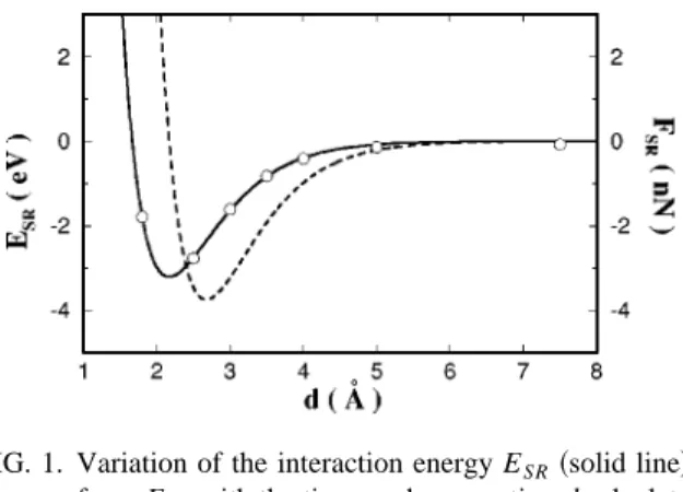
Figure 1 illustrates the variation of the interaction energy ESR(d), calculated self-consistently within the local density
approximation, and force FSR(d) derived therefrom. The
maximum attraction is;3.2 eV at d;2.1 Å and it decays and becomes negligible for d.6.5 Å . The maximum at-tractive force is 3.9 nN and occurs for d;2.7 Å ; this value is much larger than the maximum of Fex pt(d).15 In the
present work the Si tip is sharp and has a single atom at the apex, whereas the atomic structure of the apex is not charac-terized and the possibility that the tip may have more than one atom at the apex is not ruled out. So the discrepancy max$Fex pt(d)%2max$FSR(d)% would grow if we were using a blunt tip in our calculation. Clearly, the range of FSR is
rather short and cannot contribute to the measured long-range attractive force if d.8 Å .
Earlier, Perez et al.20investigated the interaction between the Si(111)-(535) surface and the sharp tips stacked in Si~111! planes that have a single atom at the apex. They carried out fully relaxed ab initio calculations for the tip moving at a constant height ~with d55 Å ) above the sur-face and obtained the corrugation of ESR(x) and FSR(x) (x
being the displacement parallel to the surface!. They con-cluded that the single Si atom at the apex of the tip that has a dangling bond directed towards the surface yields high resolution ~or high corrugation! and is due to the covalent bond forming even for d55 Å . This actually corroborates an earlier theory3,21proposing tip-induced states that enhance the STM images. The tip structure used in the present work is reminiscent of the hydrogen saturated tetrahedral tip with 4 Si atoms used by Perez et al.; both tip structures allow a dangling bond to form at the apex atom. We terminated 3 Si atoms behind the apex atom by 3 additional Si atoms ~in-stead of 3 hydrogen atoms! as a continuation of the tetrahe-dral bonding since one needs to use more plane waves to describe the Si-H bonds. Also the tip-induced deformation leads to effects on the value of calculated short-range force that can be negligible at d55 Å . As expected, the force FIG. 1. Variation of the interaction energy ESR~solid line! and
short range force FSRwith the tip-sample separation d calculated by
the self-consistent field pseudopotential method. The tip and sample are assumed to be rigid.
value calculated by Perez et al.20in fair agreement with our results of FSR50.25 nN at d55 Å .
III. MOLECULAR DYNAMICS CALCULATIONS
The effects of the tip-sample interaction and the deforma-tion induced therefrom are investigated by using a tip-sample system comprising 1367 Si atoms. In the present case, the tip and the sample have the same atomic structure, but involve more atoms and become more extended as compared to the model used in the above ab initio calculations. The substrate is made by ten Si~111! layers ~hence 1200 atoms! with the 231 reconstruction geometry leading to thep-bonded chain structure and fivefold and sevenfold rings at the surface. The sharp and pyramidal tip has 167 Si atoms that are arranged in the Si~111! layers. The top two layers of the tip and the bottom two layers of the substrate are taken to be robust. The rest of the atoms~111 tip and 960 substrate atoms! are sub-ject to relaxation under the tip-sample interaction. These at-oms are specified as dynamic atat-oms. The tip-sample system is treated by the periodic boundary condition, where each substrate layer includes 6310 Si(111)-(231) cells. The in-teraction between the atoms are calculated by using the Stillinger-Weber22 potential, which has had reasonable suc-cess in predicting the bulk defects and the reconstruction of silicon surface with coordination number lower than that in the bulk.23It is also used to investigate the stick-slip behav-ior and wear between a Si tip and the Si surface with a noncrystalline contact.24We note that the cutoff distance for the three-body interaction is only 3.6 Å in the Stillinger-Weber potential22 and hence the interaction is short range. For that reason the calculated energy and force are specified by the subscript SR. Starting from a large spacing ~5.5 Å!, the two robust layers of the Si tip are displaced towards the sample in increments ofDs50.05 Å , whereas the total dis-placement at the end of n steps is s5nDs. Between two consecutive steps of displacements, all dynamic atoms are relaxed for 2000 time steps. In each time step25 of Dt53.8 310216s, the dynamic atoms are allowed to move under the
forces calculated at the beginning of the time step. At the end of each time step, the system is thermalized to 4 K. That the number of relaxation steps is suitable for the equilibration of the tip-sample system following a 0.05 Å approach of the tip is tested by calculating the temperature and potential en-ergy variations.
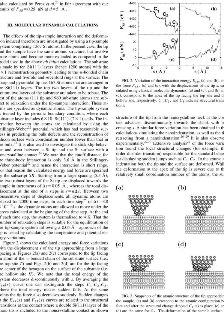
Figure 2 shows the calculated energy and force variations with the displacement s of the tip approaching from a large spacing d. Figures 2~a! and 2~c! correspond to the tip facing an atom of thep-bonded chain of the substrate surface~i.e., the top site T) and Figs. 2~b! and 2~d! are for the tip facing the center of the hexagon on the surface of the substrate~i.e. the hollow site H). We note that the total energy of the system decreases discontinuously with s. By averaging the ESR(s) curve one can distinguish the steps C1,C2,C3,
where the total energy makes sudden falls. At the same points the tip force also decreases suddenly. Sudden changes in the ESR(s) and FSR(s) curves are related to the structural transitions at the contact where a double Si~111! layer of the sharp tip is included to the noncrystalline contact as shown in Fig. 3. This way the boundary separating the ordered
structure of the tip from the noncrystalline neck at the con-tact advances discontinuously towards the shank with in-creasing s. A similar force variation has been obtained in the calculations simulating the nanoindentation, as well as the tip retracting from a nanoindentation.26–29 It is also observed experimentally.27,30 Extensive analysis29 of the force varia-tion found the local structural changes ~for example, the order-disorder transition! responsible for the standard behav-ior displaying sudden jumps such as C1,C2. In the course of
indentation both the tip and the surface are deformed. While the deformation at the apex of the tip is severe due to the relatively small coordination number of the atoms, the sur-FIG. 2. Variation of the interaction energy ESR,~a! and ~b!, and
the force FSR, ~c! and ~d!, with the displacement of the tip s,
cal-culated using classical molecular dynamics.~a! and ~c!, and ~b! and ~d!, correspond to the apex of the tip facing the top site and the hollow site, respectively. C1,C2, and C3indicate structural
transi-tions.
FIG. 3. Snapshots of the atomic structure of the tip approaching the sample.~a! and ~b! correspond to the atomic configuration be-fore and after the structural change denoted C1takes place.~c! and
~d! are the same for C2. The deformation of the sample surface is
face at the contact is deformed only locally.~The latter is not seen clearly in the side view in Fig. 3.! Practically, the sharp tip is crushed on the sample surface. The reverse situation can occur if a blunt and hard tip were pressed into a softer sample.27,31
The behavior of the deformation outlined above demon-strates that depending on the shape of the tip, the force varia-tion with s can be rather different from Fig. 1. In the present case, while the atoms at the apex form a contact and enter the repulsive force region, the second layer atoms can still be attracted by the substrate. Accordingly, the measured tip force is the resultant of the attractive as well as repulsive force acting at different regions of the tip. Depending on the material parameters, the shape, and the atomic structure of the tip, FSR can be occasionally and temporarily repulsive. Here we address an important issue, namely, the response of the cantilever to the actual force variation~or stiffness varia-tion!. Each structure of the molecular dynamics simulations corresponds to a time interval;10213 s, while the response time of a cantilever is usually larger than ;1029 s. There-fore, several structures occurring in atomic simulations can-not be sensed by the cantilever. In this respect, the force variation Fex pt(d) obtained by the integration of the
aver-aged stiffness may deviate from the actual force variation. If the tip is blunt but comprises several asperities in dif-ferent levels, the range of force can be even longer than displayed in Figs. 2~c! and 2~d!. On the other hand, ESR(s)
and FSR(s) of an atomically flat tip~without asperity! have a shorter range than those of the sharp tip ~see Fig. 4!. This demonstrates the crucial effect of the deformation leading to atomic rearrangements. Since the jump to the contact is avoided in the experiments by Jarvis et al.,15 the discussion in this section may not be directly related to Fex pt(d).
How-ever, the present study demonstrates that the tip-induced de-formation modifies the range of the net tip force in spite of the short-range interatomic force. As a result, Fex pt(s), as
well as FSR(s), where the tip and sample atoms are allowed
to relax, differs from FSR(d) in Fig. 1; the range of the attractive Fex pt(s) or FSR(s) in Fig. 2~c! or 2~d! is extended.
IV. van der WAALS INTERACTION
The van der Waals interaction occurs as a dipole-dipole interaction13,14 even if two electrodes ~tip and sample! are well separated and become completely decoupled. The im-portance of the vdW interaction in STM and AFM was rec-ognized earlier5,8,10,11 and it was argued that depending on the overall shape of the tip support, the atom at the apex of
the tip can experience strong repulsion, even leading to irre-versible deformation, while an atom farther away from the apex experiences an overall attraction. The measured force15 that exhibits a longer range has led us to examine the vdW interaction between the Si tip and the Si sample. The calcu-lation of the vdW potential might be easier if the interaction is assumed to be nonretarded and additive. Then, only the Hamaker constant A remains to be determined for the pair of materials to evaluate the integral of the pair potential of the form 2C/r6. Here C is calculated from A and depends on the materials of the tip and sample. However, the additivity breaks down when the presence of any other atom may change the polarizability of a pair of atoms. The Lifshitz theory13 redefines the Hamaker constant considering this complexity. Since the relevant d in the experiment15is rather large, the asymptotic interaction expression for a polarizable surface and single atom can be used safely. In this case, the interaction energy EvdW is given by summing 2C/t3j over the the Si tip. In our study we first focuse on the the deter-mination of the Hamaker constant for the Si tip and the Si sample and then perform the calculation of the vdW force between the tip and the sample.
The expression for the Hamaker constant can be calcu-lated from the spectral relation14
A. 3h 8p2
E
v1`
S
e~iv!21e~iv!11
D
dv. ~2! Heree is the dielectric constant of Si. For the determination of the Hamaker constant by using Eq.~2!, the variation of the dielectric permittivity as a function of imaginary frequency has to be known. A model fore(v) ande(iv) for dielectric or nonconducting materials was introduced32 by using the assumption that oscillations of the charge density of these materials behave like a single oscillator with a main absorp-tion frequency in the UV region. For conducting materials, the expression e(v)512v2p/v2 can be used, where vp is
the plasma frequency. Then the dielectric permittivity for imaginary frequencies becomes e(iv)511v2p/v2. Plasma
oscillations in the valence band are considered to be the source of the van der Waals interaction between silicon objects.33 By using the plasma frequency of silicon34 ap-proximately 3.8731015s21, we determined the Hamaker constant for the Si tip-sample system (A.0.34 aJ) from Eq.~2!. Then the constant in the Lifshitz asymptotic expres-sion is equal to A/r2p2;r is the atomic density of Si.
French et al.35assumed that the major source of the vdW interaction is interband excitation and is calculated to be A 50.21 aJ. On the other hand, the value they obtained for the Hamaker constant by using the Tabor-Winterton approximation14 is rather large, A50.67 aJ. Accordingly, the vdW force illustrated in Fig. 5 would be reduced by 38% if one were to use the first value obtained from the spectral method; in contrast, it would increase by 93% if the value obtained from the Tabor-Winterton approximation were used. On the other hand, Perez et al.20 used A50.19 aJ as determined by Senden and Drummond36 in their recent cal-culation of the long-range force. Note that the calculated values of the Hamaker constant range in the interval 0.19 aJ <A<0.67 aJ, depending on the type of excitation taken to FIG. 4. Variation of the interaction energy ESR and the force
FSR with the displacement s calculated for a blunt tip. The inset
be responsible for the vdW interaction. The value A 50.34 aJ we calculated lies near the center of the interval. Of course, the precise value of the Hamaker constant is es-sential for the calculation of FvdW. However, once the un-certainties in determining the actual shape and size of the tip are taken into account, the Hamaker constant used in the present work is suitable to estimate the variation of the long-range force and hence to analyze the experimental data.
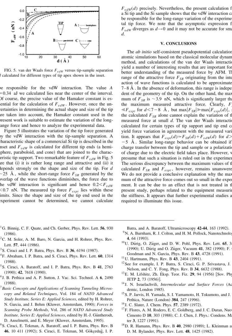
Figure 5 illustrates the variation of the tip force generated by the vdW interaction with the tip-sample separation. A characteristic shape of a commercial Si tip is described in the inset and FvdW is calculated for different tip ends ~a hemi-sphere, paraboloid, and cone! that are joined to the charac-teristic tip support. Two remarkable feature of FvdWin Fig. 5 are that ~i! it is rather long range and attractive and ~ii! it depends strongly on the shape and size of the tip. For d ;25 Å , while the short-range force FSR generated by the
overlap of the wave functions diminishes, the force due to the vdW interaction is significant and hence 0.2,FvdW ,0.7 nN. The measured tip force Fex pt lies within these
limits. Since the shape and size of the tip end used in the experiment cannot be determined, we cannot calculate
FvdW(d) precisely. Nevertheless, the present calculation for a Si tip and the Si sample shows that the vdW interaction can be responsible for the long-range variation of the experimen-tal tip force. We note that the asymptotic expression for FvdWdiverges as d→0 and it may not be accurate for small d.
V. CONCLUSIONS
The ab initio self-consistent pseudopotential calculations, atomic simulations based on the classical molecular dynamic method, and calculations of the van der Waals interaction yield a number of interesting results that are important for a better understanding of the measured force by AFM. The range of the attractive force FSR originating from the inter-action of wave functions is calculated to be approximately 7–8 Å . In the absence of deformation, this range is indepen-dent of the geometry of the tip. On the other hand, the maxi-mum of FSR is;3.9 nN, which is significantly larger than the maximum measured attractive force. Clearly, FSR
!Fex pt for d,728 Å , but maxuFSRu@maxuFex pt(d)u, so
the calculated FSR alone cannot explain the variation of the
measured force at small d. The van der Waals interaction calculated for certain types of tip support and tip end can yield force variation in agreement with the measured varia-tion. It appears that Fex pt(d).FSR(d)1FvdW(d) for d.4 25 Å . Similar long-range behavior can be obtained if a charge transfer between the tip and sample or a polarization of charge due to the electric field takes place. However, we presume that such a situation is ruled out in the experiment. The serious discrepancy between the maximum values of the calculated FSR and Fex pt, however, remains unanswered.
We do not provide a conclusive explanation why the maxi-mum of the attractive force comes out so small in the experi-ment. It can be due to an effect that is not treated in the present study, perhaps related to the equipment measuring the stiffness. It appears that further experimental studies are required to illuminate this issue.
1G. Binnig, C. F. Quate, and Ch. Gerber, Phys. Rev. Lett. 56, 930
~1986!.
2
C. M. Soler, A. M. Baro, N. Garcia, and H. Rohrer, Phys. Rev. Lett. 57, 444~1986!.
3S. Ciraci and I. P. Batra, Phys. Rev. B 36, 6194~1987!. 4F. Abraham, I. P. Batra, and S. Ciraci, Phys. Rev. Lett. 60, 1314
~1988!.
5S. Ciraci, A. Baratoff, and I. P. Batra, Phys. Rev. B 41, 2763
~1990!; 42, 7618 ~1990!.
6J. B. Pethica and A. P. Sutton, J. Vac. Sci. Technol. A 6, 2490
~1988!.
7Basic Concepts and Applications of Scanning Tunneling
Micros-copy and Related Techniques, Vol. 184 of NATO Advanced Study Institute, Series E: Applied Sciences, edited by H. Rohrer, N. Garcia, and J. Behm~Kluwer, Amsterdam, 1990!; Forces in Scanning Probe Methods, Vol. 286 of NATO Advanced Study Institute, Series E: Applied Sciences, edited by H.-J. Gu¨ntherodt, D. Anselmetti, and E. Meyer~Kluwer, Amsterdam, 1995!.
8S. Ciraci, E. Tekman, A. Baratoff, and I. P. Batra, Phys. Rev. B 46, 10 411 ~1992!; S. Ciraci, E. Tekman, M. Go¨kc½edag˘, I. P.
Batra, and A. Baratoff, Ultramicroscopy 42-44, 163~1992!.
9N. A. Burnham, R. J. Colton, and H. M. Pollock, Nanotechnology 4, 64~1993!.
10U. Du¨rig, O. Zu¨ger, and D. W. Pohl, Phys. Rev. Lett. 65, 349
~1990!; U. Du¨rig and O. Zu¨ger, Vacuum 41, 382 ~1990!; F. O. Goodman and N. Garcia, Phys. Rev. B 43, 4728~1991!.
11U. Hartmann, Phys. Rev. B 43, 2404~1991!.
12See for example, I. P. Batra, S. Ciraci, G. P. Srivastava, J. S.
Nelson, and C. Y. Fong, Phys. Rev. B 34, 6632~1988!.
13E. M. Lifshitz, Zh. E´ ksp. Teor. Fiz. 29, 94 ~1956! @Sov. Phys.
JETP 2, 73~1956!#.
14J. N. Israelachvili, Intermolecular and Surface Forces
~Aca-demic, London 1985!.
15S. P. Jarvis, H. Yamada, S. I. Yamamoto, H. Tokumoto, and J. B.
Pethica, Nature~London! 384, 247 ~1996!.
16
J. C. Slater, J. Chem. Phys. 57, 2389~1972!.
17F. Flores, A. M. Rodero, E. C. Goldberg, and J. C. Duran, Nuovo
Cimento D 10, 303~1988!; C. J. Chen, J. Phys.: Condens. Mat-ter 3, 1227~1991!.
18D. R. Hamann, Phys. Rev. B 40, 2980~1989!; L. Kleinman and
D. M. Bylander, Phys. Rev. Lett. 48, 1425~1982!. FIG. 5. van der Waals force FvdWversus tip-sample separation
19D. M. Ceperley and B. J. Adler, Phys. Rev. Lett. 45, 566~1980!. 20R. Perez, M. C. Payne, I. Stich, and K. Terakura, Phys. Rev. Lett.
78, 678~1997!. 21
E. Tekman and S. Ciraci, Physica 38, 486~1988!.
22F. H. Stillinger and T. A. Weber, Phys. Rev. B 31, 5262~1985!. 23F. Abraham, I. P. Batra, and S. Ciraci, Phys. Rev. B 35, 9552
~1987!; Phys. Rev. Lett. 60, 1314 ~1988!; F. F. Abraham and I. P. Batra, Surf. Sci. 163, L752~1985!.
24U. Landman, W. D. Luedke, and A. Nitzan, Surf. Sci. 210, L177
~1989!.
25Note that the time steps ofDt53.8310216 s are appropriate for the Newtonian dynamics in the present study. Much longerDt would lead to the jumps of atoms to local minima far from the global minimum. A similar simulation ~see Ref. 24! has used time steps approximately one order of magnitude longer and incrementsDs five times larger. Since the number of relaxation after each incrementDs can be arbitrarily large, the time interval 20003Dt57.6310213 s may not be a relevant time scale in the dynamics. For the critical discussion of the issue see also A. P. Sutton, Curr. Opin. Solid State Mater. Sci. 1, 827~1996!.
26A. P. Sutton and J. B. Pethica, J. Phys.: Condens. Matter 2, 5317
~1990!; J. A. Nieminen, A. P. Sutton, and J. B. Pethica, Acta
Metall. Mater. 40, 2503~1992!.
27U. Landman, W. D. Luedke, N. A. Burnham, and R. J. Colton,
Science 248, 454~1990!.
28
T. N. Todorov and A. P. Sutton, Phys. Rev. B 54, R14 234 ~1996!.
29A. Buldum, S. Ciraci, and I. P. Batra, Phys. Rev. B 57, 2468
~1998!.
30G. Rubio, N. Agrait, and S. Vieira, Phys. Rev. Lett. 76, 2302
~1996!; A. Stalder and U. Durig, Appl. Phys. Lett. 68, 637 ~1996!.
31A. I. Livshits and A. L. Shluger, Phys. Rev. B 56, 12 482~1997!;
C¸ . Kilic¸, H. Mehrez, and S. Ciraci, ibid. 58, 7872~1998!.
32J. Mahanty and B. W. Ninham, Dispersion Forces~Academic,
New York, 1976!.
33J. E. Inglesfield and E. Wikborg, J. Phys. F 5, 1475~1975!; J. E.
Inglesfield, ibid. 6, 687~1976!.
34C. Kittel, Introduction to Solid State Physics~Wiley, New York,
1986!.
35R. H. French, R. M. Cannon, L. K. DeNoyer, and Y. M. Chiang,
Solid State Ionics 75, 13~1995!.
36T. J. Senden and C. J. Drummond, Colloids Surf., A 94, 29