VI. CONCLUSION
Four error estimation techniques are investigated for use with adap-tive -refinement procedures, and the LCN method, for electromag-netic integral equations. For a test suite of targets, the estimators were successful at correctly locating high-error regions.
Of particular interest is the successful performance of the “disconti-nuity in ” estimator on the smooth targets under consideration. This estimator only imposes a computational cost of . Since it is unbounded at edges where the charge density is unbounded, some regularization must be applied for it to be used in that case. Residual estimators also work well and can handle general situations, but im-pose a cost of at least . This study suggests that adaptive re-finement procedures can be efficient for integral equation formulations and that future efforts are warranted to extend these ideas to general three-dimensional problems.
REFERENCES
[1] M. Ainsworth and J. T. Oden, A Posteriori Error Estimation in Finite Element Analysis. New York, NY, USA: Wiley, 2000.
[2] M. Salazar-Palma, T. K. Sarkar, L.-E. Garcia-Castillo, T. Roy, and A. Djordjevic, Iterative and Self-Adaptive Finite-Elements in Electromag-netic Modeling. Boston, MA, USA: Artech House, 1998.
[3] L. Demkowicz, Computing With HP-Adaptive Finite Elements. Boca Raton, FL, USA: Chapman & Hall/CRC, 2007, 2008, vol. 1–2. [4] G. C. Hsiao and R. E. Kleinman, “Error control in numerical solution
of boundary integral equations,” ACES J., vol. 11, pp. 32–36, 1996. [5] F. J. C. Meyer and D. B. Davidson, “A posteriori error estimates for
two-dimensional electromagnetic field computations: Boundary ele-ments and finite eleele-ments,” ACES J., vol. 11, pp. 40–54, Jul. 1996. [6] J. Wang and J. P. Webb, “Hierarchal vector boundary elements and
adaption for 3-D electromagnetic scattering,” IEEE Trans. Antennas Propag., vol. 45, pp. 1869–1879, Dec. 1997.
[7] X. Wang, M. M. Botha, and J.-M. Jin, “An error estimator for the mo-ment method in electromagnetic scattering,” Microw. Opt. Technol. Lett., vol. 44, pp. 320–326, Feb. 2005.
[8] M. Botha and D. B. Davidson, “An explicit a posteriori error indicator for electromagnetic, finite element-boundary integral analysis,” IEEE Trans. Antennas Propag., vol. 53, pp. 3717–3725, Nov. 2005. [9] E. Kita and N. Kamiya, “Error estimation and adaptive mesh
refine-ment in boundary elerefine-ment method, an overview,” Eng. Anal. Boundary Elements, vol. 25, pp. 479–495, 2001.
[10] U. Saeed and A. F. Peterson, “Local residual error estimators for the method of moments solution of electromagnetic integral equations,” ACES J., vol. 26, pp. 403–410, May 2011.
[11] U. Saeed and A. F. Peterson, “Adaptive refinement for the locally-cor-rected Nystrom method based on an implicit error estimation scheme,” in Proc. 27th Annu. Review of Progress in Applied Computational Elec-tromagnetics, Williamsburg, VA, USA, Mar. 2011, pp. 666–670. [12] L. F. Canino, J. J. Ottusch, M. A. Stalzer, J. L. Visher, and S. M.
Wandzura, “Numerical solution of the Helmholtz equation in 2D and 3D using a high-order Nyström discretization,” J. Comp. Phys., vol. 146, pp. 627–663, 1998.
[13] A. F. Peterson and M. M. Bibby, An Introduction to the Locally-Cor-rected Nyström Method, ser. Synthesis Lectures on Computational Electromagnetics. San Rafael, CA, USA: Morgan & Claypool, 2010. [14] A. F. Peterson, “Accuracy of currents produced by the locally-cor-rected Nyström method and the method of moments when used with higher-order representations,” ACES J., vol. 17, pp. 74–83, Mar. 2002. [15] M. M. Bibby and A. F. Peterson, “On the use of over-determined sys-tems in the adaptive numerical solution of integral equations,” IEEE Trans. Antennas Propag., vol. 53, pp. 2267–2273, Jul. 2005. [16] M. M. Bibby and A. F. Peterson, “High-order treatment of junctions
and edge singularities with the locally-corrected Nyström method,” ACES J., vol. 28, pp. 892–902, Oct. 2013.
Reconfigurable Nested Ring-Split Ring Transmitarray Unit Cell Employing the Element Rotation
Method by Microfluidics
Emre Erdil, Kagan Topalli, Nasim S. Esmaeilzad, Özge Zorlu, Haluk Kulah, and Ozlem Aydın Civi
Abstract—A continuously tunable, circularly polarized X-band microflu-idic transmitarray unit cell employing the element rotation method is de-signed and fabricated. The unit cell comprises a double layer nested ring-split ring structure realized as microfluidic channels embedded in Poly-dimethylsiloxane (PDMS) using soft lithography techniques. Conductive regions of the rings are formed by injecting a liquid metal (an alloy of Ga, In, and Sn), whereas the split region is air. Movement of the liquid metal together with the split around the ring provides 360 linear phase shift range in the transmitted field through the unit cell. A circularly po-larized unit cell is designed to operate at 8.8 GHz, satisfying the necessary phase shifting conditions provided by the element rotation method. Unit cell prototypes are fabricated and the proposed concept is verified by the mea-surements using waveguide simulator method, within the frequency range of 8–10 GHz. The agreement between the simulation and measurement re-sults is satisfactory, illustrating the viability of the approach to be used in reconfigurable antennas and antenna arrays.
Index Terms—Beam steering, circularly polarized, element rotation method, lens array, liquid metal, microfluidics, reconfigurable, split ring, transmitarray.
I. INTRODUCTION
Transmitarrays are promising alternatives to parabolic reflectors, di-electric lenses, and phased arrays for the applications requiring high gain antennas. They collimate the incident spherical wave emitted from a feed antenna by tuning the phase of the transmitted wave of each array element at a specific value. Dynamical reconfiguration of the phase distribution over the array surface enables beam steering. To this end, switches, varactors, microelectromechanical systems (MEMS) compo-nents, or phase shifters are used for reconfiguration [1]–[4]. Detailed review of transmitarrays with an extensive list of references can be found in [5].
In this work, the element rotation method is applied to control the phase of the transmitted field. Transmitarrays employing this method and comprising stacked microstrip patches and nested split ring slots as elements have been presented in [6], [7]. Rotation of the elements can be realized mechanically (e.g., by using motors controlling the rotation angle of the unit cells) as suggested in [8]. However, the placement of the motor for each element of the array is not practical and it might also ruin the RF performance since most transmitarrays utilize double sided radiating structures. The other approach to realize element rotation is
Manuscript received February 19, 2014; revised September 22, 2014; ac-cepted December 12, 2014. Date of publication January 05, 2015; date of current version March 02, 2015. This work was supported in part by TUBITAK project no: 113R033.
E. Erdil, N. S. Esmaeilzad, H. Kulah, and O. Aydın Civi are with the Depart-ment of Electrical and Electronics Engineering, Middle East Technical Univer-sity, Ankara, Turkey (e-mail: [email protected]; [email protected]; [email protected]; [email protected]).
K. Topalli is with National Nanotechnology Research Center, Bilkent Uni-versity, Ankara, Turkey (e-mail: [email protected]).
Ö. Zorlu and H. Kulah are with the METU-MEMS Research and Appli-cation Centre, Middle East Technical University, Ankara, Turkey (e-mail: [email protected]).
Color versions of one or more of the figures in this communication are avail-able online at http://ieeexplore.ieee.org.
Digital Object Identifier 10.1109/TAP.2014.2387424 0018-926X © 2015 IEEE. Personal use is permitted, but republication/redistribution requires IEEE permission.
antennas and fluidically tunable frequency selective and phase shifting surfaces have been developed [10]–[12]. The idea of applying mi-crofluidics to implement the element rotation method is first presented by the authors of this work in [13], and is demonstrated with a trans-mitarray unit cell comprising double layer nested split ring slots by simulations. In the unit cell structure, the micro-channels were formed inside a PDMS layer placed on a gold coated substrate [13]. However, the low bonding quality of the PDMS to the gold surface was very low, which results in a low yield process. To alleviate this issue, the idea is adapted to a complementary structure, namely, a nested ring-split ring structure where the PDMS layer is directly bonded to the glass layer and a completely new structure based on a microfluidic implementation is designed, fabricated and measured. The following sections of the paper present the design, fabrication, and measurement of the microfluidic nested ring-split ring based transmitarray unit cell.
II. DESIGN OF THENESTEDRING-SPLITRINGUNITCELL The unit cell is designed in an infinite array environment with a Flo-quet port excitation using Ansys HFSS. At each FloFlo-quet port defined on the apertures of both sides of the unit cell, the scattered waves are decomposed into Floquet modes. When the unit cell size is smaller than a half wavelength, only - and -polarized wave modes propa-gate for a plane wave propagating along -axis [6]. Under these cir-cumstances, the following conditions should be satisfied for an ideal phase shifting transmitarray unit cell: (i) The pol transmission co-efficients ( and ) at the frequency at which two waves have the same magnitude should be out of phase, (ii) the magnitude of and should be maximized at that frequency, (iii) the reflections should be minimized [6], [13]. Satisfying these conditions, the phase of the transmitted wave changes linearly by two times the rotation angle with a high co-pol radiation.
The novel transmitarray unit cell presented in this paper comprises nested ring-split ring elements where the rings are in the form of mi-crofluidic channels inside the PDMS layer which is directly bonded to the glass substrate. The liquid metal is confined in these channels and forms the conductive parts in the structure whereas the air gap of the channel forms the split region. Changing the position of the split along the channel by rotating the liquid metal realizes the rotation of the ele-ment around the normal to the plane of the structure. The liquid metal used is an alloy of 68.5% Ga, 21.5% In, and 10% Sn, a product of Gal-liumSource, LLC [14]. The split region takes place on the inner ring keeping outer ring full of liquid metal. The dimensions of the unit cell are 11.43 mm 10.16 mm, approximately at 12 GHz. Since the waveguide simulator method [15] is used for the characterization of the fabricated unit cells, these dimensions are chosen to ensure that two adjacent unit cells strictly fit into the WR-90 waveguide which has dimensions of 22.86 mm 10.16 mm.
In the design of the unit cell, the depth of the rings (channels) is taken as 0.2 mm. The PDMS layers
have thicknesses of 1.75 mm. The substrate between the layers is glass and the thickness of it is a parameter to sat-isfy the aforementioned design conditions. In order to have a phase dif-ference between and , the resonance frequencies of the structure for each orthogonal polarized propagating wave should be different.
Fig. 1. (a) Geometry of the double layer nested ring-split ring transmitarray unit cell. Simulated (b) magnitude and (c) phase of the pol transmission co-efficients for - and -polarized incident waves. (d) The transmission phase, the phase of , with respect to the rotation angle at 8.8 GHz.
This can be achieved by making the characteristic impedance of the structure different for those propagations. To obtain the required dif-ference in impedance, in our design, a split is placed on the inner ring and adjusting the radii of the rings, glass substrate thickness, ring width and split length, the conditions on and are satisfied. The oper-ating frequency of the design is the frequency when and have equal magnitude and are out of phase, and the insertion loss is equal to that value. Therefore, changes in the characteristics of and by changing the values of the physical parameters affect the insertion loss of the design.
An SRR can be modeled by parallel connection of an inductance and capacitance. The capacitance is formed between the conductive rings whereas the inductance can be approximated as that of a single ring with averaged radius of midpoint between the nested rings and width of a single ring [16]. The increment in the split length increases the resonance frequency and the frequency of intersection by decreasing the inductance and capacitance values since the inductance and capac-itance depends on the length of the ring and the conductive area be-tween the rings, respectively. The change in the split length results in an increment or decrement in the frequency difference between the or-thogonal resonances. The design is optimized for the split length on the inner ring of 2.05 mm and the substrate thickness of 5.5 mm such that the magnitudes of and are equalized and the phase difference between them is 180 at 8.8 GHz. The rings have 0.5 mm of width and the midpoint of the inner ring radius is 2.9 mm whereas it is 4.3 mm for the outer ring. Fig. 1(b) and (c) show the transmission and phase characteristics. Fig. 1(d) shows the phase of the circularly polarized transmitted wave versus the rotation angle of the split, obtained by the simulations. It is observed that the phase of the circularly polarized transmitted wave changes linearly with the rotation angle, as expected. Furthermore, the full 360 of phase range is obtained.
The circularly polarized parameters can be obtained from linearly polarized parameters [6]. Fig. 2(a) shows the magnitude of the circu-larly polarized scattered waves with respect to the frequency. The sub-scripts of the parameters denote the port whereas the supersub-scripts and denote the hand of the polarization, left-hand and right-hand, respec-tively. For a left hand circularly polarized excitation, in the vicinity of 8.8 GHz, the co-pol transmission component is right hand circularly po-larized and the phase of this component changes linearly with the
Fig. 2. Magnitude of the scattered waves with respect to (a) frequency and (b) rotation angle at 8.8 GHz.
Fig. 3. Magnitude of with respect to the incidence angle at 8.8 GHz.
rotation angle as seen in Fig. 1(d). It is also observed in Fig. 2(a) that the cross-pol transmission component ( and right hand reflected com-ponent are suppressed significantly; whereas left hand reflected component is 7–8 dB below co-polarized transmitted wave.
When the magnitude variation of the scattered waves with respect to the rotation angle is examined in Fig. 2(b), it can be deduced that, the magnitude of the circularly polarized co-pol component ( has a variation between dB and dB with respect to the rotation angle indicating that the structure can be employed as a unit cell in a complete transmitarray.
Fig. 3 shows the insertion loss with respect to the incidence angle, which is the angle between the direction of propagation and the surface normal. The insertion loss is less than 3 dB for the incidence angle up to 40 .
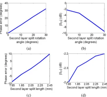
In order to assess the sensitivity of the design with respect to fab-rication tolerances, several simulations were carried out. One of the major source of fabrication related sensitivity is the slip of the liquid location and change in the split length from the designed values, which may occur during the injection of the liquid metal. Keeping the split length and the position as the designed value for one layer, these values are parameterized for the other layer in the simulations and the effects on transmission are observed. It is seen from Fig. 4 that the change in the angular position has a more pronounced effect on the transmis-sion magnitude. Because, the cross-pol transmistransmis-sion increases as the angular position of the split between the layers differs from each other.
III. FABRICATION
The steps of the fabrication process of the microfluidic transmitarray unit cell are shown in Fig. 5. The microfluidic channels are formed by using soft lithography techniques by using a DRIE-etched silicon mold wafer for shaping the PDMS (Fig. 5(a), (b)). PDMS is poured on the mold wafer and cured at room temperature. After peeling off the PDMS layer from the mold wafer, PDMS pieces are bonded on glass pieces
Fig. 4. The phase and magnitude characteristics with respect to the changes in the split parameters in one layer at 8.8 GHz. (a) Phase error and (b) the transmis-sion magnitude of when the angular position of the split in the second layer changes with respect to the split in the first layer. (c) Phase error and (d) the transmission magnitude of with respect to the change in the length of the split in the second layer.
Fig. 5. Fabrication process flow: (a) mold wafer preparation via DRIE process, (b) PDMS coating, curing, and peeling off, (c) PDMS-to-glass bonding process, and (d) Liquid metal injection.
(Fig. 5(c)). Prior to bonding process, glass samples are cleaned in ace-tone. PDMS-glass bonding is performed by applying oxygen plasma to the PDMS piece for 20 seconds at 30 mT pressure. Then the bond is sealed by baking the bonded pieces on a hot plate at 120 C for 20 min-utes. The liquid metal [14], is then injected into the channel in order to form the outer ring and the inner split ring of the single layer structure (Fig. 5(d)). Double layer is formed by stacking two single layer struc-tures back to back (glass sides facing each other) with 9 other glass pieces in between, each having 0.5 mm thickness. The rotation of the liquid metal along the channels and fixing its position can be provided by using micropumps attached to the channels as implemented by the previous work in the literature [10].
The major advantage of the proposed reconfigurable unit cell struc-ture is that each unit cell can be controlled by a pair of tubes connected to a micropump whereas, in the realization of 2D beam steering trans-mitarrays by switches, varactors and phase shifters, each such com-ponent of each unit cell should be controlled individually which may require even more complicated biasing network. A microfluidic feed network that can be used to implement continuous beam steering full
Fig. 6. A microfluidic feed network injecting liquid metal and controlling the position of the splits to realize a transmitarray.
Fig. 7. (a) One layer of the fabricated double layer transmitarray unit cells for the rotation angle of 20 . (b) The double layer transmitarray unit cell with di-mensions 22.86 mm 10.16 mm 9 mm.
transmitarray is shown in Fig. 6. This network can be used to insert the liquid metal into the channel and then to provide the control of the split position by utilizing micropumps attached to the ends of the channel. The location of the conductive fluid can be dynamically adjusted by applying air pressure or by moving the conductive fluid droplets inside a fluidic medium showing dielectric properties with micropumps.
For the proof-of-concept demonstration of the structure, six double layer unit cells having different split positions corresponding to the rotation angle of 0 –10 –20 –30 –80 –90 are fabricated and mea-sured. Fig. 7(a) shows the photograph of one layer of the fabricated unit cell for the rotation angle of 20 . Fig. 7(b) shows one of the six fabricated double layer transmitarray unit cells.
IV. MEASUREMENT OF THEUNITCELL
The fabricated unit cells are placed into a WR-90 waveguide piece and TRL (Thru, Reflect, Line) calibration is employed in order to move the measurement planes to the unit cell plane. Since the components of a waveguide set up which is appropriate to characterize circularly po-larized unit cells as given in [17] are not available in our laboratory; in the measurements, the sample is excited by a single linearly polarized wave, TE mode. To verify the measurement results, in the simula-tion environment, two adjacent unit cells are placed inside a waveguide with boundaries being perfect electric conductor and excited with the fundamental mode. It should be noted that the use of linearly polarized excitation instead of circularly polarized one that the element rotation method requires, prevents the observation of linear phase shifting cor-responding to the change in the rotation angle. However, the agreement
loss value which mainly causes the mismatch between the measure-ment and simulation characteristics shown in Fig. 8. It can be noticed that phases of measured and simulated are very close to each other at the design frequency, 8.8 GHz.
It can be observed from plots in Fig. 8 that, the insertion loss value at the design frequency is varying with the rotation angle. This variation is due to the fact that measurement and simulation results shown in Fig. 8 are obtained for the unit cell under the linear polarized incidence. This situation can be explained as follows.
The relation between the incident and scattered waves for single linear polarized excitation is
(1)
where and represent the incident and scattered waves and the sub-scripts of and represent the port numbers. When the element is rotated, the rotated scattering matrix is,
(2) where the rotation matrix for a two port system is defined as,
(3)
From the rotated S-matrix, we can obtain the transmission coefficient
by taking and for a double layer structure with
identical layers, as,
(4) From (4), it can be deduced that the magnitude of the transmission coefficient changes with the rotation angle for a linear polarized mea-surement. Since the transmission coefficient is multiplied by a real number, , the angular position differences between the measured and simulated unit cells do not result in a significant difference in the phase of as much as in the amplitude.
The amplitude taper of the TE incidence has also an effect on the value of the insertion loss as the rotation angle changes. Besides, the incidence angle of TE excitation is 42 for a WR-90 waveguide at 8.8 GHz, which also has an effect on the insertion loss level as demon-strated in Fig. 3 for a circularly polarized wave.
It is worthwhile to mention once more that the insertion loss of the circularly polarized unit cell is around 2–3 dB and the variation with respect to rotation angle remains in 1 dB (Fig. 2(b)).
V. CONCLUSION
This paper presents a novel microfluidic based proof-of-concept re-configurable transmitarray unit cell employing the element rotation method. The unit cell consists of double layer nested ring-split rings implemented as micro-channels in PDMS. The reconfigurability in the transmission phase is provided by the movement of the liquid metal
Fig. 8. (a)–(l) Comparison of the linear polarized measurement and sim-ulation results for the transmission coefficient characteristics and insertion phase of the fabricated double layer transmitarray unit cells rotated at 0 –10 –20 –30 –80 –90 .
inside the ring shaped micro-channels. The proposed method and the designed unit cell ensure 0 –360 continuous and linear phase shifting capability, without using any additional phase shifting mechanism and
without increasing the size of the unit cell. The fabricated unit cell is measured in a waveguide set-up and the design is verified by the mea-surements. Only a few degrees of phase difference are observed be-tween the measured and simulated transmitted fields. In some samples, magnitude of the measured transmitted wave deviates from the sim-ulated ones. This degradation in the performance is due to fact that liquid metal is inserted manually into the channels which causes mis-alignments of the splits in the unit cell. This problem can be solved by using micropumps with high precision control. The design can be easily scaled to different frequency bands since the structure and the chan-nels are manufactured using micromachining techniques that enable the high precision fabrication capability required for high frequency applications.
REFERENCES
[1] J. Mazotta, L.-Y. Chen, and J.-C. Chiao, “Reconfigurable transmission-type beamformer,” in Proc. IEEE MTT-S Int. Microwave Symp. Digest, 2000, vol. 1, pp. 585–588.
[2] J. Y. Lau and S. V. Hum, “A wideband reconfigurable transmitarray el-ement,” IEEE Trans. Antennas Propag., vol. 60, no. 3, pp. 1303–1311, Mar. 2012.
[3] M. Sazegar, Z. Yuliang, C. Kohler, H. Maune, M. Nikfalazar, J. R. Binder, and R. Jakoby, “Beam steering transmitarray using tunable fre-quency selective surface with integrated ferroelectric varactors,” IEEE Trans. Antennas Propag., vol. 60, no. 12, pp. 5690–5699, Dec. 2012. [4] C. Chih-Chieh, B. Lakshminarayanan, and A. Abbaspour-Tamijani,
“A programmable lens-array antenna with monolithically integrated MEMS switches,” IEEE Trans. Microwave Theory Tech., vol. 57, no. 8, pp. 1874–1884, Aug. 2009.
[5] S. V. Hum and J. Perruisseau-Carrier, “Reconfigurable reflectarrays and array lenses for dynamic antenna beam control: A review,” IEEE Trans. Antennas Propag., vol. 62, no. 1, pp. 183–198, Jan. 2014. [6] R. H. Phillion and M. Okoniewski, “Lenses for circular polarization
using planar arrays of rotated passive elements,” IEEE Trans. Antennas Propag., vol. 59, no. 4, pp. 1217–1227, Apr. 2011.
[7] M. Euler and V. F. Fusco, “Frequency selective surface using nested split ring slot elements as a lens with mechanically reconfigurable beam steering capability,” IEEE Trans. Antennas Propag., vol. 58, no. 10, pp. 3417–3421, Oct. 2010.
[8] R. H. Phillion and M. Okoniewski, “Improving the phase resolution of a micromotor-actuated phased reflectarray,” in Proc. Microsystems and Nanoelectronics Research Conf., 2008, pp. 169–172.
[9] C. Guclu, J. Perruisseau-Carrier, and O. Aydın Civi, “Proof of concept of a dual-band circularly-polarized RF MEMS beam-switching reflec-tarray,” IEEE Trans. Antennas Propag., vol. 60, no. 11, pp. 5451–5455, Nov. 2012.
[10] D. Rodrigo, L. Jofre, and B. A. Cetiner, “Circular beam-steering recon-figurable antenna with liquid metal parasitics,” IEEE Trans. Antennas Propag., vol. 60, no. 4, pp. 1796–1802, Apr. 2012.
[11] G. J. Hayes, J. H. So, A. Qusba, M. D. Dickey, and G. Lazzi, “Flexible liquid metal alloy (EGaIn) microstrip patch antenna,” IEEE Trans. An-tennas Propag., vol. 60, no. 5, pp. 2151–2156, May 2012.
[12] M. Li and N. Behdad, “Fluidically tunable frequency selective/phase shifting surfaces for high-power microwave applications,” IEEE Trans. Antennas Propag., vol. 60, no. 6, pp. 2748–2759, Jun. 2012. [13] E. Erdil, K. Topalli, O. Zorlu, T. Toral, E. Yildirim, H. Kulah, and
O. Aydın Civi, “A reconfigurable microfluidic transmitarray unit cell,” in Proc. 7th Eur. Conf. on Antennas and Propagation (EuCAP), Apr. 8–12, 2013, pp. 2957–2960.
[14] [Online]. Available: www.galliumsource.com
[15] P. Hannan and M. Balfour, “Simulation of a phased-array antenna in waveguide,” IEEE Trans. Antennas Propag., vol. 13, no. 3, pp. 342–353, May 1965.
[16] J. D. Baena, J. Bonache, F. Martin, R. M. Sillero, F. Falcone, T. Lopetegi, M. A. G. Laso, J. Garcia-Garcia, I. Gil, M. F. Portillo, and M. Sorolla, “Equivalent-circuit models for split-ring resonators and complementary split-ring resonators coupled to planar transmission lines,” IEEE Trans. Microwave Theory Tech., vol. 53, no. 4, pp. 1451–1461, Apr. 2005.
[17] S. Mener, R. Gillard, R. Sauleau, C. Cheymol, and P. Potier, “Design and characterization of a CPSS-based unit-cell for circularly polarized reflectarray applications,” IEEE Trans. Antennas Propag., vol. 61, no. 4, pp. 2313–2318, Apr. 2013.